EP0600610B1 - Système et méthode pour déterminer une position - Google Patents
Système et méthode pour déterminer une position Download PDFInfo
- Publication number
- EP0600610B1 EP0600610B1 EP93308694A EP93308694A EP0600610B1 EP 0600610 B1 EP0600610 B1 EP 0600610B1 EP 93308694 A EP93308694 A EP 93308694A EP 93308694 A EP93308694 A EP 93308694A EP 0600610 B1 EP0600610 B1 EP 0600610B1
- Authority
- EP
- European Patent Office
- Prior art keywords
- wand
- subject
- emitters
- receivers
- image data
- Prior art date
- Legal status (The legal status is an assumption and is not a legal conclusion. Google has not performed a legal analysis and makes no representation as to the accuracy of the status listed.)
- Expired - Lifetime
Links
Images



Classifications
-
- A—HUMAN NECESSITIES
- A61—MEDICAL OR VETERINARY SCIENCE; HYGIENE
- A61B—DIAGNOSIS; SURGERY; IDENTIFICATION
- A61B17/00—Surgical instruments, devices or methods
- A61B17/34—Trocars; Puncturing needles
- A61B17/3403—Needle locating or guiding means
-
- A—HUMAN NECESSITIES
- A61—MEDICAL OR VETERINARY SCIENCE; HYGIENE
- A61B—DIAGNOSIS; SURGERY; IDENTIFICATION
- A61B34/00—Computer-aided surgery; Manipulators or robots specially adapted for use in surgery
- A61B34/20—Surgical navigation systems; Devices for tracking or guiding surgical instruments, e.g. for frameless stereotaxis
-
- A—HUMAN NECESSITIES
- A61—MEDICAL OR VETERINARY SCIENCE; HYGIENE
- A61B—DIAGNOSIS; SURGERY; IDENTIFICATION
- A61B90/00—Instruments, implements or accessories specially adapted for surgery or diagnosis and not covered by any of the groups A61B1/00 - A61B50/00, e.g. for luxation treatment or for protecting wound edges
- A61B90/10—Instruments, implements or accessories specially adapted for surgery or diagnosis and not covered by any of the groups A61B1/00 - A61B50/00, e.g. for luxation treatment or for protecting wound edges for stereotaxic surgery, e.g. frame-based stereotaxis
-
- A—HUMAN NECESSITIES
- A61—MEDICAL OR VETERINARY SCIENCE; HYGIENE
- A61B—DIAGNOSIS; SURGERY; IDENTIFICATION
- A61B10/00—Instruments for taking body samples for diagnostic purposes; Other methods or instruments for diagnosis, e.g. for vaccination diagnosis, sex determination or ovulation-period determination; Throat striking implements
- A61B10/02—Instruments for taking cell samples or for biopsy
-
- A—HUMAN NECESSITIES
- A61—MEDICAL OR VETERINARY SCIENCE; HYGIENE
- A61B—DIAGNOSIS; SURGERY; IDENTIFICATION
- A61B17/00—Surgical instruments, devices or methods
- A61B17/00234—Surgical instruments, devices or methods for minimally invasive surgery
-
- A—HUMAN NECESSITIES
- A61—MEDICAL OR VETERINARY SCIENCE; HYGIENE
- A61B—DIAGNOSIS; SURGERY; IDENTIFICATION
- A61B17/00—Surgical instruments, devices or methods
- A61B2017/0046—Surgical instruments, devices or methods with a releasable handle; with handle and operating part separable
- A61B2017/00473—Distal part, e.g. tip or head
-
- A—HUMAN NECESSITIES
- A61—MEDICAL OR VETERINARY SCIENCE; HYGIENE
- A61B—DIAGNOSIS; SURGERY; IDENTIFICATION
- A61B17/00—Surgical instruments, devices or methods
- A61B2017/00477—Coupling
-
- A—HUMAN NECESSITIES
- A61—MEDICAL OR VETERINARY SCIENCE; HYGIENE
- A61B—DIAGNOSIS; SURGERY; IDENTIFICATION
- A61B34/00—Computer-aided surgery; Manipulators or robots specially adapted for use in surgery
- A61B34/10—Computer-aided planning, simulation or modelling of surgical operations
- A61B2034/107—Visualisation of planned trajectories or target regions
-
- A—HUMAN NECESSITIES
- A61—MEDICAL OR VETERINARY SCIENCE; HYGIENE
- A61B—DIAGNOSIS; SURGERY; IDENTIFICATION
- A61B34/00—Computer-aided surgery; Manipulators or robots specially adapted for use in surgery
- A61B34/20—Surgical navigation systems; Devices for tracking or guiding surgical instruments, e.g. for frameless stereotaxis
- A61B2034/2046—Tracking techniques
- A61B2034/2051—Electromagnetic tracking systems
-
- A—HUMAN NECESSITIES
- A61—MEDICAL OR VETERINARY SCIENCE; HYGIENE
- A61B—DIAGNOSIS; SURGERY; IDENTIFICATION
- A61B34/00—Computer-aided surgery; Manipulators or robots specially adapted for use in surgery
- A61B34/20—Surgical navigation systems; Devices for tracking or guiding surgical instruments, e.g. for frameless stereotaxis
- A61B2034/2046—Tracking techniques
- A61B2034/2055—Optical tracking systems
-
- A—HUMAN NECESSITIES
- A61—MEDICAL OR VETERINARY SCIENCE; HYGIENE
- A61B—DIAGNOSIS; SURGERY; IDENTIFICATION
- A61B34/00—Computer-aided surgery; Manipulators or robots specially adapted for use in surgery
- A61B34/20—Surgical navigation systems; Devices for tracking or guiding surgical instruments, e.g. for frameless stereotaxis
- A61B2034/2068—Surgical navigation systems; Devices for tracking or guiding surgical instruments, e.g. for frameless stereotaxis using pointers, e.g. pointers having reference marks for determining coordinates of body points
-
- A—HUMAN NECESSITIES
- A61—MEDICAL OR VETERINARY SCIENCE; HYGIENE
- A61B—DIAGNOSIS; SURGERY; IDENTIFICATION
- A61B90/00—Instruments, implements or accessories specially adapted for surgery or diagnosis and not covered by any of the groups A61B1/00 - A61B50/00, e.g. for luxation treatment or for protecting wound edges
- A61B90/36—Image-producing devices or illumination devices not otherwise provided for
- A61B2090/363—Use of fiducial points
-
- A—HUMAN NECESSITIES
- A61—MEDICAL OR VETERINARY SCIENCE; HYGIENE
- A61B—DIAGNOSIS; SURGERY; IDENTIFICATION
- A61B90/00—Instruments, implements or accessories specially adapted for surgery or diagnosis and not covered by any of the groups A61B1/00 - A61B50/00, e.g. for luxation treatment or for protecting wound edges
- A61B90/39—Markers, e.g. radio-opaque or breast lesions markers
- A61B2090/3954—Markers, e.g. radio-opaque or breast lesions markers magnetic, e.g. NMR or MRI
-
- A—HUMAN NECESSITIES
- A61—MEDICAL OR VETERINARY SCIENCE; HYGIENE
- A61B—DIAGNOSIS; SURGERY; IDENTIFICATION
- A61B90/00—Instruments, implements or accessories specially adapted for surgery or diagnosis and not covered by any of the groups A61B1/00 - A61B50/00, e.g. for luxation treatment or for protecting wound edges
- A61B90/39—Markers, e.g. radio-opaque or breast lesions markers
- A61B2090/3983—Reference marker arrangements for use with image guided surgery
-
- A—HUMAN NECESSITIES
- A61—MEDICAL OR VETERINARY SCIENCE; HYGIENE
- A61B—DIAGNOSIS; SURGERY; IDENTIFICATION
- A61B34/00—Computer-aided surgery; Manipulators or robots specially adapted for use in surgery
- A61B34/10—Computer-aided planning, simulation or modelling of surgical operations
-
- A—HUMAN NECESSITIES
- A61—MEDICAL OR VETERINARY SCIENCE; HYGIENE
- A61B—DIAGNOSIS; SURGERY; IDENTIFICATION
- A61B90/00—Instruments, implements or accessories specially adapted for surgery or diagnosis and not covered by any of the groups A61B1/00 - A61B50/00, e.g. for luxation treatment or for protecting wound edges
- A61B90/06—Measuring instruments not otherwise provided for
-
- A—HUMAN NECESSITIES
- A61—MEDICAL OR VETERINARY SCIENCE; HYGIENE
- A61B—DIAGNOSIS; SURGERY; IDENTIFICATION
- A61B90/00—Instruments, implements or accessories specially adapted for surgery or diagnosis and not covered by any of the groups A61B1/00 - A61B50/00, e.g. for luxation treatment or for protecting wound edges
- A61B90/39—Markers, e.g. radio-opaque or breast lesions markers
Definitions
- This invention relates to a position determining system and method. It finds particular application in conjunction with neurosurgery and will be described with particular reference thereto. However, it is to be appreciated, that the invention will also find application in conjunction with other medical procedures, industrial quality control procedures, and the like.
- Three-dimensional diagnostic image data of the brain and other body portions are commonly available with CT scanners, magnetic resonance images, and other medical diagnostic equipment. These imaging modalities provide structural detail with a resolution of a millimetre or better.
- a three-dimensional "localizer” is attached to the patient's skull.
- the localizer is a mechanical device with precisely known geometry and dimensions for guiding or positioning surgical instruments.
- the localizer is commonly attached to a ring or frame of metal or plastic from which the name "framed" stereotaxy has evolved. This frame is typically affixed to the patient using various mounting hardware methods that include sharp points or pins that pierce the skin and locate into the skull.
- the localizer is then mounted onto a frame.
- the localizer and frame provide the surgeon with the ability to position surgical instruments mechanically with a mechanical accuracy of a millimetre or better. However, anatomically, accuracy is somewhat less due to inaccuracies in the diagnostic imaging and patient motion.
- a frameless position determining system is know from document IEEE Transactions on biomedical engineering, vol.36, no.6, June 1989, New York, US, pages 608-617. This document discloses to coordinate the coordinate system of the patient's skull with the coordinate system of the diagnostic data by placing a sound emitter on marks on the patient's skull and detecting their respective positions by three receivers.
- a position determining system comprising: a subject support; a means for securing a preselected portion of a subject to the subject support; a frame assembly which mounts at least three receivers in a fixed relationship to the subject support closely adjacent the means for securing a portion of the subject to the subject support; at least one reference emitter mounted a fixed, known distance from the receivers, the reference emitter emitting a reference signal which travels from the reference emitter the fixed distance to the receivers; a calibration means for measuring a reference travel time of the reference signal over the fixed distance; a wand having a pointer and at least two emitters mounted thereto, the two wand emitters selectively emitting wand signals which are received by the at least three receivers; a wand position determining means for determining a position of the wand pointer by measuring wand signal travel times of the wand signals between the two wand emitters and the at least three receivers, the wand
- a position determining method comprising: a) securing a portion of a subject to a subject supporting surface in close proximity to at least three signal receivers that are mounted in a fixed relationship to the subject supporting surface; b) positioning a wand to designate selected locations on the subject portion, the wand having at least two wand emitters mounted thereon for selectively emitting signals which are received by the receivers; c) actuating the wand emitters to emit wand signals; d) from the wand emitter signals, calculating coordinates of the wand emitters in a coordinate system of the subject support; e) comparing a calculated distance between calculated wand emitter coordinates and a physical distance between the wand emitters; f) in response to the difference between the calculated distance and the physical distance exceeding a preselected standard, providing an unacceptable measurement signal.
- a position determining method comprising: a) securing a portion of a subject to a subject supporting surface in close proximity to at least three signal receivers that are mounted in a fixed relationship to the subject supporting surface, a reference signal emitter being fixedly mounted at a fixed, known distance from the plurality of receivers; b) positioning a wand to designate selected locations on the subject portion, the wand having at least two wand emitters mounted thereon for selectively emitting signals which are received by the receivers; c) actuating the wand emitters individually and the reference emitter in close temporal proximity to emit wand and reference signals; d) measuring travel durations for the wand and reference signals to travel from each of the wand emitters to the receivers and from the reference emitter to the receivers; e) from the travel times, calculating coordinates of the locations designated by the wand in a coordinate system of the subject support.
- One advantage of an apparatus and method embodying the present invention is that it provides a technique which simply and painlessly coordinates the coordinate system of three-dimensional image data obtained from one or more imaging modalities with the coordinate system of the patient prior to or during surgery.
- Another advantage of an apparatus and method embodying the present invention is that no frame is needed during the image acquisition scan.
- Another advantage of an apparatus and method embodying the present invention is that sterilization of necessary parts of the system is facilitated.
- Another advantage of an apparatus and method embodying the present invention is that it is easy to use and very user friendly.
- a subject such as a human patient
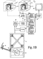
- a frame 12 is fixed to the patient support such that it is precisely positioned within the subject or subject support coordinate system. Mounting the frame 12 to the patient support permits the patient support to be turned, raised, lowered, wheeled to another location, or the like, without altering the patient coordinate system.
- the frame 12 supports a plurality of emitter/receiver combinations 14 mounted at fixed, known locations thereon.
- a head clamp 16 or other means securely positions the patient's head or other portion of the subject under consideration in the subject support coordinate system.
- the frame is mounted at a fixed or selectable angle from vertical such that the frame is positionable more toward the patient, yet still focusing on the region of interest of the patient.
- an operator console 18 houses a computer system 20 .
- the computer system can be remotely located and connected with the control console 18 by cabling.
- the computer system includes a three-dimensional data memory 22 .
- the stored three-dimensional image data preferably contains a video pixel value for each voxel or point in a three-dimensional rectangular grid of points, preferably a 256 x 256 x 256 grid.
- each image value represents one millimeter cube
- the image data represents about a 25.6 centimeter cube through the patient with one millimeter resolution.
- a plane selecting means 24 selects various two-dimensional planes of pixel values from the three-dimensional memory for display.
- the plane selecting means selects at least three planes: axial, sagittal, coronal, and oblique planes through a selectable point of the patient.
- the pixel values which lie on the selected axial, sagittal, coronal, and oblique planes are copied into corresponding image memories 26a , 26b , 26c , and 26d .
- a video processor means 28 converts the two-dimensional digital image representations from one or more of image memories 26 into appropriate signals for display on video monitors 30 or other appropriate display means.
- the surgeon positions a tip 40 of a wand 42 at the desired location.
- the locator system locates the coordinate of the tip and the trajectory of the wand.
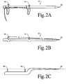
- the wand includes a pair of emitters 44 and 46 which selectively emit positioning signals, ultrasonic signals in the preferred embodiment.
- the first emitter 44 has a fixed, known distance l 1 from the tip 40 and the second emitter has a fixed, known distance l 2 from the first emitter 44 .
- the wand is readily sterilized by conventional techniques.
- the two emitters and the tip are preferably in linear alignment.
- the wand 42 may have a jog 48 which enables the tip and the two emitters to be disposed along a central axis or pointing direction of the wand.
- the frame 12 includes not only the plurality of receivers, e.g. microphones 50 in the preferred ultrasonic embodiment, but also a plurality of reference emitters 52 .
- the reference receivers are each spaced along side edges of the frame from adjacent receivers or microphones 50 by distances S 1 and S 2 .
- Each reference receiver is also spaced by a distance D across the frame from an oppositely disposed emitter 52 .
- the emitters and the microphones are normally not coplanar with the frame 12 .
- both distances or range values D are equal in length.
- the distance from the wand emitters to the frame, hence the position of the wand relative to the patient, is determined by the travel time of the sound.
- the velocity of the sound pulse through air is dependent upon both the temperature, the humidity, and the chemical composition of the air. These factors can and do vary significantly during an operation and from procedure to procedure.
- a calculation is performed to determine the speed of sound in the operating room.
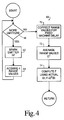
- a calibrating means 60 selectively pulses the reference emitters 52 , receives the signals at receivers 50 , and processes the elapsed time information in accordance with the procedure of FIGURE 4.
- the calibration means 60 includes a step or means 62 for causing a first of the reference emitters 50 to emit a signal pulse.
- a step or means 64 acquires the range values D', i.e. the time required for the ultrasonic pulses to traverse the distance D.
- a step or means 66 causes this procedure to be repeated a preselected number of times, such as once for each of the four emitters illustrated in FIGURE 3.
- a step or means 70 corrects the times for fixed machine delays. That is, there is a fixed, small delay between the time when the command is given to fire the reference emitters 52 and the time that they actually produce a detectable ultrasonic signal. Analogously, there is a small delay between the time that the ultrasonic pulses reach the receiver or microphone 50 and the time that it becomes a measurable electrical signal received by the computer processor. These delays are subtracted from the times measured by step or means 64 .
- An averaging means 72 averages the actual times after correction for the machine delays for transmission of the ultrasonic pulse between the transmitter and receiver. The time over the range values D' provide the most accurate results.
- a step or means 74 computes a calibration factor F indicative of the current speed of the ultrasound signal adjacent the patient in the operating room. In the preferred embodiment, the calibration factor F is a ratio of the sonically measured distance D' versus a precise mechanical measurement of the distance D.
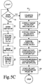
- a wand coordinate and trajectory determining means 80 determines the position of the two emitters 44 and 46 , respectively. More specifically, a step or means 82 causes the emitter 44 to emit an ultrasonic signal. The receivers 50 on the frame 12 receive the ultrasonic signal at corresponding times L 1 -L 4 . A step or means 84 acquires and retains these times. A step or means 86 causes the second emitter 46 to transmit. A step or means 88 acquires the four times L 1 -L 4 which are required for the ultrasonic signals to pass from the second emitter to the microphones 50 .
- a step or means 90 causes the emitters to emit and corresponding data values L 1 -L 4 to be acquired each of a plurality of times to improve digitation accuracy, e.g. two times.
- a step or means 92 causes the calibration means 60 to perform the steps described in conjunction with FIGURE 4 in order to provide a current indication of the velocity of sound adjacent the patient.
- the calibration procedure of FIGURE 4 may be performed immediately before steps 82-88 or intermittently during the collection of several data values for averaging.
- a step or means 94 corrects the values values L 1 -L 4 for the fixed machine delay discussed above in conjunction with step or means 70 .
- a step or means 96 corrects each of the times L 1 -L 4 that were required for the ultrasonic signals to travel from the first and second emitters 44 , 46 to the microphones 50 in accordance with the correction factor F determined by step or means 74 .
- An averaging means 98 averages the delay and calibration corrected times L 1 -L 4 , hence distances between each of the wand emitters 44 , 46 and each of the microphones 50 . From these distances, provided at least three receivers 50 are provided, a step or means 100 calculates the Cartesian coordinates (x 1 ,y 1 ,z 1 ) and (x 2 ,y 2 ,z 2 ) in the patient space for the two emitters 44 and 46 . The first emitter coordinates x 1 ,y 1 ,z 1 are calculated from three of the four range values L 1 -L 4 .
- the three selected range values are the three shortest of L 1 -L 4 .
- Similar computations are calculated for x 2 , y 2 , and z 2 coordinates of the second emitter.
- a step or means 102 checks the validity of the measurement.
- the known separation between the wand emitters is compared with the separation between the measured coordinates x 1 y 1 ,z 1 and x 2 ,y 2 ,z 2 of the wand emitters, i.e.:
- ⁇ error If the difference between the measured and known separations is greater than the acceptable error, e.g. 0.75 mm when measuring with a resolution of 1 mm, an erroneous measurement signal is given. The measurement is discarded and the surgeon or other user is flagged to perform the measurement process 80 again.
- a transform means 110 transforms the coordinates of patient space into the coordinate system of the image data and vice versa. More specifically, prior to the imaging, three or more fiducials or markers are affixed at three or more spaced points on the patient's head. The fiducials are visible in the imaging medium selected such that they show up as readily identifiable dots 112 in the resultant image data. In thepreferred embodiment, the fiducials are markers or small beads 114 that are injected with radiation opaque and magnetic resonance excitable materials. A small dot or tattoo is made on the patient's skin and a fiducial is glued to each dot.
- portions of the markers can be portions of the patient's anatomy which are readily identifiable in both patient and image space, e.g. the tip of the nose.
- the tip of the wand is placed on each fiducial or tattooed marker point. The coordinates in patient space of each fiducial are determined with the procedure described in conjunction with FIGURES 5A-5C.
- the position of the three or more fiducials on the patient's scalp are compared with the relative position of the pixels 112 in the image space.
- the patient space coordinates of marks 114 on the patient's skull in the coordinate system of the patient support are measured.
- a like coordinate system through the pixels 112 is defined and compared to the patient space coordinate system.
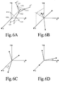
- the translation and rotational relationship between image space and patient space coordinate systems is determined. With reference to FIGURE 6A, the position of the patient in operating room space (x,y,z) and the relative position in image space (x',y',z') are determined. That is, two coordinate systems are defined.
- the translation means first determines the offset x offset , y offset , z offset between the barycenters 116 , 118 of the triangles defined by the coordinates of three fiducials in data and patient space, respectively. This provides a translation or an offset in the x, y, and z-directions between the two coordinate systems.
- the values of x offset , y offset , and z offset are added or subtracted to the coordinates of the patient space and the coordinates of image space, respectively, to translate between the two.
- translating the origins of the two coordinate systems into alignment is not the complete correction. Rather, the coordinate systems are normally also rotated relative to each other about all three axes whose origin is at the barycenter. As illustrated in FIGURES 6B, 6C, and 6D, the angle of rotation in the (y,z), (x,z), and (x,y) planes are determined. Having made these determinations, it is a simple matter to transform the patient support space coordinates into the image space coordinates and, conversely, to rotate the image space coordinates into patient space coordinates.
- the wand coordinate means 80 is connected through the transform means 110 with one of the plane selecting means 24 and the video processor 28 to cause a marker, e.g. cross hairs, to be displayed on the monitors 30 at the coordinates of the wand tip. This enables the surgeon to coordinate specific points on the patient or in the incision with the images.
- an additional three-dimensional data memory 22 ' may store additional diagnostic data, e.g. from another modality, from the same modality, but at different time or with different imaging characteristics, or the like.
Landscapes
- Health & Medical Sciences (AREA)
- Surgery (AREA)
- Life Sciences & Earth Sciences (AREA)
- Engineering & Computer Science (AREA)
- Animal Behavior & Ethology (AREA)
- General Health & Medical Sciences (AREA)
- Biomedical Technology (AREA)
- Heart & Thoracic Surgery (AREA)
- Medical Informatics (AREA)
- Molecular Biology (AREA)
- Nuclear Medicine, Radiotherapy & Molecular Imaging (AREA)
- Veterinary Medicine (AREA)
- Public Health (AREA)
- Pathology (AREA)
- Robotics (AREA)
- Oral & Maxillofacial Surgery (AREA)
- Image Processing (AREA)
- Magnetic Resonance Imaging Apparatus (AREA)
- Length Measuring Devices By Optical Means (AREA)
- Measurement Of The Respiration, Hearing Ability, Form, And Blood Characteristics Of Living Organisms (AREA)
Claims (23)
- Système de détermination de position comprenant : un support de sujet (10) ; un moyen (16) destiné à fixer une partie préchoisie d'un sujet sur le support de sujet (10) ; un ensemble formant cadre (12) qui porte au moins trois récepteurs (50) dans une relation fixe par rapport au support de sujet (10), à proximité immédiatement du moyen (16) destiné à fixer une partie du sujet au support de sujet (10) ; au moins un émetteur de référence (52) monté à une distance fixe, connue, des récepteurs (50), l'émetteur de référence (52) émettant un signal de référence qui parcourt la distance fixe de l'émetteur de référence (52) aux récepteurs (50) ; un moyen (60) de calibrage destiné à mesurer un temps de parcours de référence du signal de référence sur la distance fixe ; un crayon (42) comportant un pointeur (40) et au moins deux émetteurs (44, 46) montés sur celui-ci, les deux émetteurs (44, 46) de crayon émettant, sélectivement, des signaux de crayon qui sont reçus par au moins trois récepteurs (50) ; un moyen (80) de détermination de position de crayon destiné à déterminer une position du pointeur (40) de crayon en mesurant des temps de parcours de signaux de crayon, des signaux de crayon, entre les deux émetteurs (44, 46) de crayon et les au moins trois récepteurs (50), le moyen (80) de détermination de position de crayon étant connecté au moyen (60) de calibrage pour calibrer les temps de parcours de signaux de crayon à l'aide du temps de parcours de référence.
- Système selon la revendication 1, comprenant en outre : un moyen de mémorisation d'image tridimensionnelle destiné à mémoriser des données d'image indicatives d'une région tridimensionnelle de la partie du sujet qui est fixée au moyen de support de sujet ; un moyen de choix de plan destiné à choisir des coupes planes de données provenant du moyen de mémorisation d'image tridimensionnelle ; un moyen d'affichage destiné à convertir les coupes choisies de données provenant du moyen de choix de plan en affichages lisibles par l'homme ; un moyen de transformation destiné à transformer une position du pointeur de crayon en un système de coordonnées des données d'image mémorisées dans le moyen de mémorisation d'image tridimensionnelle, le moyen de transformation étant connecté de manière fonctionnelle avec le moyen de choix de plan de façon que les images affichées aient une relation préchoisie par rapport à la position du pointeur de crayon.
- Système selon la revendication 2, dans lequel l'ensemble formant cadre est monté directement sur le support de sujet pour être mobile avec celui-ci, de façon qu'un déplacement du support de sujet n'altère pas le système de coordonnées de sujet.
- Système selon la revendication 2, dans lequel l'ensemble formant cadre est monté, sur le support de sujet, avec un certain angle à partir d'une relation perpendiculaire pour se concentrer sur la région fixée de sujet, même lorsqu'il est monté à l'écart de la région fixée du sujet.
- Système selon la revendication 2, dans lequel le sujet est un patient humain.
- Système selon la revendication 2, comprenant en outre : au moins trois marqueurs disposés sur la partie choisie de sujet, les marqueurs ayant été fixés au sujet lors de l'acquisition de données d'image tridimensionnelle, de façon que les emplacements des trois marqueurs soient identifiables dans les données d'image tridimensionnelle, les marqueurs étant identifiables sur la surface du sujet ; un moyen de calcul de transformation destiné à calculer une transformation entre les positions des marqueurs sur le sujet, désignées en plaçant sélectivement le crayon sur chacun des marqueurs, les emplacements de marqueur se trouvant dans les données d'image tridimensionnelle, et ainsi des relations de translation et de rotation entre un système de coordonnées d'espace de sujet et un système de coordonnées d'espace de données d'image tridimensionnelle.
- Système selon la revendication 6, dans lequel les marqueurs contiennent des matières qui sont visibles par des techniques, à la fois, d'imagerie de tomodensitométrie (CT) et de résonance magnétique, de façon que l'on puisse utiliser les mêmes marqueurs pour des examens, à la fois, par tomodensitométrie et résonance magnétique.
- Système selon la revendication 1, dans lequel plusieurs émetteurs de référence sont montés sur le cadre dans des relations fixes par rapport aux récepteurs.
- Système selon la revendication 1, dans lequel le crayon comprend une partie de pointe, une partie s'étendant le long d'un axe de pointage du crayon, et une partie décalée qui est décalée de l'axe de pointage du crayon, les émetteurs de crayon étant montés dans une relation espacée par rapport à la section décalée, en alignement avec l'axe de pointage du crayon de façon que la pointe de crayon et les deux actionneurs soient colinéaires.
- Système selon l'une quelconque des revendications précédentes, lequel est un système de stéréotaxie.
- Procédé de détermination de position comprenant : a) la fixation d'une partie d'un sujet à une surface de support de sujet, à proximité immédiate d'au moins trois récepteurs de signaux qui sont montés dans une relation fixe par rapport à la surface de support de sujet ; b) le placement d'un crayon pour désigner des emplacements choisis sur la partie de sujet, le crayon comportant au moins deux émetteurs de crayon montés sur celui-ci, destinés à émettre, sélectivement, des signaux qui sont reçus par les récepteurs ; c) l'activation des émetteurs de crayon pour qu'ils émettent des signaux de crayon ; d) le calcul, à partir des signaux d'émetteurs de crayon, de coordonnées des émetteurs de crayon dans un système de coordonnées du support de sujet ; e) la comparaison d'une distance calculée entre les coordonnées calculées d'émetteurs de crayon et d'une distance physique entre les émetteurs de crayon ; f) en réponse au fait que la différence entre la distance calculée et la distance physique dépasse une norme préchoisie, la délivrance d'un signal de mesure non acceptable.
- Procédé de détermination de position comprenant : a) la fixation d'une partie d'un sujet à une surface de support de sujet, à proximité immédiate d'au moins trois récepteurs de signaux qui sont montés dans une relation fixe par rapport à la surface de support de sujet, un émetteur de signal de référence étant monté fixe, à une distance fixe, connue, des récepteurs ; b) le placement d'un crayon pour désigner des emplacements choisis sur la partie de sujet, le crayon comportant au moins deux émetteurs de crayon montés sur celui-ci, destinés à émettre, sélectivement, des signaux qui sont reçus par les récepteurs ; c) la mise en action, individuellement, d'une façon rapprochée dans le temps, des émetteurs de crayon et de l'émetteur de référence, pour émettre des signaux de crayon et de référence ; d) la mesure des temps de parcours des signaux de crayon et de référence pour aller de chacun des émetteurs de crayon aux récepteurs et de l'émetteur de référence aux récepteurs ; e) le calcul, à partir des temps de parcours, des coordonnées des emplacements désignés par le crayon, dans un système de coordonnées du support de sujet.
- Procédé selon la revendication 12, comprenant en outre : le calcul d'une distance entre les émetteurs de crayon ; la comparaison de la distance calculée entre les émetteurs de crayon avec une distance physique mesurée préalablement entre les émetteurs pour vérifier une précision acceptable de la mesure.
- Procédé selon la revendication 13, comprenant en outre la stérilisation du crayon.
- Procédé selon la revendication 13, comprenant en outre la répétition des étapes (b) à (e), le crayon se trouvant dans un second emplacement, pour calculer les coordonnées du second emplacement, et comprenant en outre la détermination, à partir des coordonnées des premier et second emplacements, de la distance les séparant.
- Procédé selon la revendication 13, dans lequel l'étape de calcul des coordonnées de système de coordonnées de support de sujet comprend : la détermination de temps de parcours entre les émetteurs de crayon et les récepteurs, les temps de parcours relatifs entre chaque émetteur et les récepteurs étant indicatifs d'un emplacement de chaque émetteur ; la correction d'au moins l'un de (i) les temps de parcours relatifs entre les émetteurs de crayon et les récepteurs et de (ii) les positions déterminées des émetteurs en fonction du temps de parcours entre l'émetteur de référence et au moins l'un des récepteurs, en corrigeant ainsi la position du crayon de variations de vitesse de transmission de signal pouvant être attribuées à des variations de température, d'humidité, et autres conditions au voisinage du sujet.
- Procédé selon la revendication 16, dans lequel : les deux émetteurs de crayon sont actionnés plusieurs fois en alternance ; l'émetteur de référence est actionné au moins une fois ; les temps de parcours sont ajustés pour des retards entre (i) la mise en action de l'émetteur et l'émission du signal et entre (ii) le signal atteignant le récepteur et sa conversion en un signal électronique de cadencement ; l'étape de correction comprend la correction des temps de parcours entre les émetteurs de crayon et les récepteurs en fonction du temps de parcours entre l'émetteur de référence et les récepteurs ; et comprenant en outre : le calcul de moyenne des temps de parcours corrigés et la détermination de coordonnées pour chaque émetteur de crayon ; le calcul, à partir des coordonnées d'émetteur de crayon, d'une coordonnée d'une partie pointe du crayon.
- Procédé selon la revendication 13, comprenant en outre le fait : de mener un premier examen diagnostic non invasif de la partie de sujet et de créer des données électroniques d'image tridimensionnelle de celui-ci ; de mémoriser les données d'image tridimensionnelle ; de déterminer une transformation entre le premier système de coordonnées de données d'image et le système de coordonnées de support de sujet.
- Procédé selon la revendication 18, comprenant en outre le fait : de mener un second examen diagnostic non invasif de la partie de sujet et de créer les données électroniques d'image tridimensionnelle de celui-ci ; de mémoriser les données d'image tridimensionnelle du second examen ; de déterminer une transformation entre le second système de coordonnées de données d'image et le système de coordonnées de support de sujet ; de déterminer une relation entre les premier et second systèmes de coordonnées de données d'image.
- Procédé selon la revendication 18, dans lequel l'étape de détermination de transformation comprend : le montage d'au moins trois marqueurs visibles d'examen non invasif sur la partie de sujet de façon que les données d'image tridimensionnelle de diagnostic comprennent les indications d'au moins trois marqueurs ; le crayon désignant une position de chacun des trois marqueurs et déterminant une coordonnée de chaque marqueur dans le système de coordonnées de support de sujet ; la comparaison des coordonnées des marqueurs dans le système de coordonnées de support de sujet et d'une position des indications de marqueur dans le système de coordonnées de données d'image pour déterminer au moins un décalage de translation entre les systèmes de coordonnées de données d'image et de support de sujet et un décalage en rotation entre les systèmes de coordonnée de support de sujet et de données d'image.
- Procédé selon la revendication 18, dans lequel le sujet est un patient vivant.
- Procédé selon la revendication 12, dans lequel la partie de sujet est la tête d'un patient.
- Procédé selon l'une quelconque des revendications 11 à 22, lequel est un procédé de stéréotaxie.
Applications Claiming Priority (2)
| Application Number | Priority Date | Filing Date | Title |
|---|---|---|---|
| US07/983,390 US5309913A (en) | 1992-11-30 | 1992-11-30 | Frameless stereotaxy system |
| US983390 | 1992-11-30 |
Publications (3)
| Publication Number | Publication Date |
|---|---|
| EP0600610A2 EP0600610A2 (fr) | 1994-06-08 |
| EP0600610A3 EP0600610A3 (fr) | 1995-06-07 |
| EP0600610B1 true EP0600610B1 (fr) | 1998-06-03 |
Family
ID=25529928
Family Applications (1)
| Application Number | Title | Priority Date | Filing Date |
|---|---|---|---|
| EP93308694A Expired - Lifetime EP0600610B1 (fr) | 1992-11-30 | 1993-11-01 | Système et méthode pour déterminer une position |
Country Status (4)
| Country | Link |
|---|---|
| US (1) | US5309913A (fr) |
| EP (1) | EP0600610B1 (fr) |
| JP (1) | JPH07148180A (fr) |
| DE (1) | DE69318944T2 (fr) |
Cited By (4)
| Publication number | Priority date | Publication date | Assignee | Title |
|---|---|---|---|---|
| US6445943B1 (en) | 1994-09-15 | 2002-09-03 | Visualization Technology, Inc. | Position tracking and imaging system for use in medical applications |
| DE102006036575A1 (de) * | 2006-08-04 | 2008-02-14 | Siemens Ag | Medizinische Bildgebungsvorrichtung und Verfahren zur Darstellung der Position eines interventionellen Instruments bei einer solchen Bildgebungsvorrichtung |
| US7787936B2 (en) | 2004-01-23 | 2010-08-31 | Traxyz Medical, Inc. | Methods and apparatus for performing procedures on target locations in the body |
| US8473026B2 (en) | 1994-09-15 | 2013-06-25 | Ge Medical Systems Global Technology Company | System for monitoring a position of a medical instrument with respect to a patient's body |
Families Citing this family (233)
| Publication number | Priority date | Publication date | Assignee | Title |
|---|---|---|---|---|
| US5251127A (en) * | 1988-02-01 | 1993-10-05 | Faro Medical Technologies Inc. | Computer-aided surgery apparatus |
| US6331180B1 (en) | 1988-05-03 | 2001-12-18 | Sherwood Services Ag | Target-centered stereotaxtic surgical arc system with reorientatable arc axis |
| FR2652928B1 (fr) | 1989-10-05 | 1994-07-29 | Diadix Sa | Systeme interactif d'intervention locale a l'interieur d'une zone d'une structure non homogene. |
| EP1690511B1 (fr) | 1990-10-19 | 2010-07-14 | St. Louis University | Système de détermination de la position d'une sonde chirurgicale par rapport à la tête |
| US6347240B1 (en) | 1990-10-19 | 2002-02-12 | St. Louis University | System and method for use in displaying images of a body part |
| US6405072B1 (en) * | 1991-01-28 | 2002-06-11 | Sherwood Services Ag | Apparatus and method for determining a location of an anatomical target with reference to a medical apparatus |
| US6006126A (en) | 1991-01-28 | 1999-12-21 | Cosman; Eric R. | System and method for stereotactic registration of image scan data |
| US5330485A (en) * | 1991-11-01 | 1994-07-19 | Clayman David A | Cerebral instrument guide frame and procedures utilizing it |
| US5603318A (en) * | 1992-04-21 | 1997-02-18 | University Of Utah Research Foundation | Apparatus and method for photogrammetric surgical localization |
| JP3432825B2 (ja) | 1992-08-14 | 2003-08-04 | ブリテイッシュ・テレコミュニケーションズ・パブリック・リミテッド・カンパニー | 位置決定システム |
| US6757557B1 (en) | 1992-08-14 | 2004-06-29 | British Telecommunications | Position location system |
| US5517990A (en) * | 1992-11-30 | 1996-05-21 | The Cleveland Clinic Foundation | Stereotaxy wand and tool guide |
| US5787886A (en) * | 1993-03-19 | 1998-08-04 | Compass International Incorporated | Magnetic field digitizer for stereotatic surgery |
| US5483961A (en) * | 1993-03-19 | 1996-01-16 | Kelly; Patrick J. | Magnetic field digitizer for stereotactic surgery |
| WO1994023647A1 (fr) * | 1993-04-22 | 1994-10-27 | Pixsys, Inc. | Systeme de determination de la position relative d'objets |
| EP0997109B1 (fr) * | 1993-04-26 | 2003-06-18 | ST. Louis University | Indication de la position d'une sonde chirurgicale |
| WO1996011624A2 (fr) | 1994-10-07 | 1996-04-25 | St. Louis University | Systemes de guidage chirurgical comprenant des cadres de reference et de localisation |
| US5558091A (en) * | 1993-10-06 | 1996-09-24 | Biosense, Inc. | Magnetic determination of position and orientation |
| US6120465A (en) | 1994-01-24 | 2000-09-19 | Radionics Software Applications, Inc. | Virtual probe for a stereotactic digitizer for use in surgery |
| US20040015176A1 (en) * | 1994-06-20 | 2004-01-22 | Cosman Eric R. | Stereotactic localizer system with dental impression |
| WO1996003087A1 (fr) * | 1994-07-22 | 1996-02-08 | University Of Washington | Procede d'implantation stereotaxique |
| JP3135068B2 (ja) | 1994-09-15 | 2001-02-13 | ビジュアリゼイション テクノロジー インコーポレイテッド | 患者の頭部に固定された基準ユニットを用いた医学的応用に使用される位置追跡及び画像生成システム |
| EP1380266B1 (fr) * | 1994-09-15 | 2005-01-12 | OEC Medical Systems, Inc. | Système d'imagerie et de recherche de position destiné à des applications médicales |
| US6978166B2 (en) * | 1994-10-07 | 2005-12-20 | Saint Louis University | System for use in displaying images of a body part |
| EP0714636B1 (fr) * | 1994-11-28 | 2003-04-16 | The Ohio State University | Dispositif d'intervention médicale |
| US5682890A (en) * | 1995-01-26 | 1997-11-04 | Picker International, Inc. | Magnetic resonance stereotactic surgery with exoskeleton tissue stabilization |
| US5588430A (en) * | 1995-02-14 | 1996-12-31 | University Of Florida Research Foundation, Inc. | Repeat fixation for frameless stereotactic procedure |
| US5868673A (en) * | 1995-03-28 | 1999-02-09 | Sonometrics Corporation | System for carrying out surgery, biopsy and ablation of a tumor or other physical anomaly |
| US5592939A (en) | 1995-06-14 | 1997-01-14 | Martinelli; Michael A. | Method and system for navigating a catheter probe |
| EP0845959A4 (fr) * | 1995-07-16 | 1998-09-30 | Ultra Guide Ltd | Pointage de guide d'aiguille a mains libres |
| GB9515446D0 (en) * | 1995-07-27 | 1995-09-27 | Marconi Gec Ltd | Imaging systems |
| US6351659B1 (en) | 1995-09-28 | 2002-02-26 | Brainlab Med. Computersysteme Gmbh | Neuro-navigation system |
| DE19536180C2 (de) * | 1995-09-28 | 2003-05-08 | Brainlab Ag | Verfahren und Vorrichtungen zur Lokalisierung eines Instruments |
| US5769861A (en) * | 1995-09-28 | 1998-06-23 | Brainlab Med. Computersysteme Gmbh | Method and devices for localizing an instrument |
| CH691569A5 (de) * | 1995-10-12 | 2001-08-31 | Zeiss Carl | Medizinisches Therapie- und/oder Diagnosegerät mit sterilisierbarem Positionserfassungsaufsetzteil. |
| US5772594A (en) * | 1995-10-17 | 1998-06-30 | Barrick; Earl F. | Fluoroscopic image guided orthopaedic surgery system with intraoperative registration |
| ES2241037T3 (es) | 1996-02-15 | 2005-10-16 | Biosense Webster, Inc. | Determinacion precisa de la posicion de endoscopios. |
| DE69726576T2 (de) | 1996-02-15 | 2004-10-14 | Biosense, Inc., Miami | Probe zur Ortsmarkierung |
| US6253770B1 (en) | 1996-02-15 | 2001-07-03 | Biosense, Inc. | Catheter with lumen |
| IL125761A (en) * | 1996-02-15 | 2005-05-17 | Biosense Inc | Independently positionable transducers for location system |
| DE69733815T2 (de) | 1996-02-15 | 2006-06-08 | Biosense Webster, Inc., Diamond Bar | Sonde zur exkavation |
| WO1997029678A2 (fr) | 1996-02-15 | 1997-08-21 | Biosense Inc. | Systeme de controle de l'etalonnage et de l'utilisation d'un catheter |
| US6453190B1 (en) | 1996-02-15 | 2002-09-17 | Biosense, Inc. | Medical probes with field transducers |
| ES2243976T3 (es) * | 1996-02-15 | 2005-12-01 | Biosense Webster, Inc. | Bobinas moviles de transmision o recepcion para sistema de localizacion. |
| DE69733341T2 (de) | 1996-02-27 | 2006-02-02 | Biosense Webster, Inc., Diamond Bar | Ortungsverfahren mit feldbestätigungssequenzen |
| US6167145A (en) | 1996-03-29 | 2000-12-26 | Surgical Navigation Technologies, Inc. | Bone navigation system |
| US5782765A (en) * | 1996-04-25 | 1998-07-21 | Medtronic, Inc. | Medical positioning system |
| IL126864A (en) | 1996-05-06 | 2003-05-29 | Biosense Inc | Method and apparatus for calibrating a magnetic field generator |
| US6408107B1 (en) | 1996-07-10 | 2002-06-18 | Michael I. Miller | Rapid convolution based large deformation image matching via landmark and volume imagery |
| US6226418B1 (en) | 1997-11-07 | 2001-05-01 | Washington University | Rapid convolution based large deformation image matching via landmark and volume imagery |
| US6296613B1 (en) | 1997-08-22 | 2001-10-02 | Synthes (U.S.A.) | 3D ultrasound recording device |
| US5951571A (en) * | 1996-09-19 | 1999-09-14 | Surgical Navigation Specialist Inc. | Method and apparatus for correlating a body with an image of the body |
| US6142937A (en) * | 1996-10-11 | 2000-11-07 | Carl-Zeiss-Stiftung | Medical therapeutic and/or diagnostic appliance with a sterilizable position sensing attachment |
| US5902239A (en) * | 1996-10-30 | 1999-05-11 | U.S. Philips Corporation | Image guided surgery system including a unit for transforming patient positions to image positions |
| US7302288B1 (en) * | 1996-11-25 | 2007-11-27 | Z-Kat, Inc. | Tool position indicator |
| US6314310B1 (en) | 1997-02-14 | 2001-11-06 | Biosense, Inc. | X-ray guided surgical location system with extended mapping volume |
| US5841830A (en) * | 1997-02-19 | 1998-11-24 | Picker International, Inc. | 3D CT fluoroscopy |
| US6731966B1 (en) | 1997-03-04 | 2004-05-04 | Zachary S. Spigelman | Systems and methods for targeting a lesion |
| US6119033A (en) * | 1997-03-04 | 2000-09-12 | Biotrack, Inc. | Method of monitoring a location of an area of interest within a patient during a medical procedure |
| USD422706S (en) * | 1997-04-30 | 2000-04-11 | Surgical Navigation Technologies | Biopsy guide tube |
| US6752812B1 (en) | 1997-05-15 | 2004-06-22 | Regent Of The University Of Minnesota | Remote actuation of trajectory guide |
| US6267769B1 (en) | 1997-05-15 | 2001-07-31 | Regents Of The Universitiy Of Minnesota | Trajectory guide method and apparatus for use in magnetic resonance and computerized tomographic scanners |
| US6434507B1 (en) | 1997-09-05 | 2002-08-13 | Surgical Navigation Technologies, Inc. | Medical instrument and method for use with computer-assisted image guided surgery |
| US6226548B1 (en) | 1997-09-24 | 2001-05-01 | Surgical Navigation Technologies, Inc. | Percutaneous registration apparatus and method for use in computer-assisted surgical navigation |
| US6081336A (en) * | 1997-09-26 | 2000-06-27 | Picker International, Inc. | Microscope calibrator |
| US6147480A (en) * | 1997-10-23 | 2000-11-14 | Biosense, Inc. | Detection of metal disturbance |
| USD420132S (en) * | 1997-11-03 | 2000-02-01 | Surgical Navigation Technologies | Drill guide |
| US6021343A (en) | 1997-11-20 | 2000-02-01 | Surgical Navigation Technologies | Image guided awl/tap/screwdriver |
| IL122336A0 (en) * | 1997-11-27 | 1998-04-05 | Ultra Guide Ltd | System and method for guiding the movements of a device to a target particularly for medical applications |
| US6064904A (en) * | 1997-11-28 | 2000-05-16 | Picker International, Inc. | Frameless stereotactic CT scanner with virtual needle display for planning image guided interventional procedures |
| US6035228A (en) * | 1997-11-28 | 2000-03-07 | Picker International, Inc. | Frameless stereotactic arm apparatus and method of using same |
| US6052611A (en) * | 1997-11-28 | 2000-04-18 | Picker International, Inc. | Frameless stereotactic tomographic scanner for image guided interventional procedures |
| US5967982A (en) * | 1997-12-09 | 1999-10-19 | The Cleveland Clinic Foundation | Non-invasive spine and bone registration for frameless stereotaxy |
| US6348058B1 (en) | 1997-12-12 | 2002-02-19 | Surgical Navigation Technologies, Inc. | Image guided spinal surgery guide, system, and method for use thereof |
| US6223066B1 (en) | 1998-01-21 | 2001-04-24 | Biosense, Inc. | Optical position sensors |
| DE19819928A1 (de) | 1998-05-05 | 1999-11-11 | Philips Patentverwaltung | Verfahren für ein Schichtbilder erzeugendes Abbildungssystem |
| AU742207B2 (en) | 1998-06-22 | 2001-12-20 | Ao Technology Ag | Fiducial matching by means of fiducial screws |
| US6118845A (en) | 1998-06-29 | 2000-09-12 | Surgical Navigation Technologies, Inc. | System and methods for the reduction and elimination of image artifacts in the calibration of X-ray imagers |
| US6477400B1 (en) | 1998-08-20 | 2002-11-05 | Sofamor Danek Holdings, Inc. | Fluoroscopic image guided orthopaedic surgery system with intraoperative registration |
| US6482182B1 (en) | 1998-09-03 | 2002-11-19 | Surgical Navigation Technologies, Inc. | Anchoring system for a brain lead |
| EP1115328A4 (fr) * | 1998-09-24 | 2004-11-10 | Super Dimension Ltd | Systeme et procede permettant de localiser un catheter lors d'un examen medical endocorporel |
| US6195577B1 (en) | 1998-10-08 | 2001-02-27 | Regents Of The University Of Minnesota | Method and apparatus for positioning a device in a body |
| WO2000021442A1 (fr) | 1998-10-09 | 2000-04-20 | Surgical Navigation Technologies, Inc. | Separateur vertebral guide par image |
| US6373240B1 (en) | 1998-10-15 | 2002-04-16 | Biosense, Inc. | Metal immune system for tracking spatial coordinates of an object in the presence of a perturbed energy field |
| US6633686B1 (en) | 1998-11-05 | 2003-10-14 | Washington University | Method and apparatus for image registration using large deformation diffeomorphisms on a sphere |
| US6285902B1 (en) | 1999-02-10 | 2001-09-04 | Surgical Insights, Inc. | Computer assisted targeting device for use in orthopaedic surgery |
| US7590441B2 (en) * | 1999-03-11 | 2009-09-15 | Biosense, Inc. | Invasive medical device with position sensing and display |
| US7575550B1 (en) | 1999-03-11 | 2009-08-18 | Biosense, Inc. | Position sensing based on ultrasound emission |
| US7558616B2 (en) * | 1999-03-11 | 2009-07-07 | Biosense, Inc. | Guidance of invasive medical procedures using implantable tags |
| US7549960B2 (en) | 1999-03-11 | 2009-06-23 | Biosense, Inc. | Implantable and insertable passive tags |
| US7174201B2 (en) * | 1999-03-11 | 2007-02-06 | Biosense, Inc. | Position sensing system with integral location pad and position display |
| ES2260901T3 (es) | 1999-03-17 | 2006-11-01 | Synthes Ag Chur | Dispositivo de planificacion y guia in situ de un injerto de ligamentos. |
| AU3905000A (en) * | 1999-03-22 | 2000-10-09 | Arc Second, Inc. | Method for creating a user-selectable coordinate frame |
| US6662103B1 (en) | 1999-03-22 | 2003-12-09 | Arc Second Inc. | Method and system for creating a user-selectable arbitrary coordinate frame |
| US6470207B1 (en) | 1999-03-23 | 2002-10-22 | Surgical Navigation Technologies, Inc. | Navigational guidance via computer-assisted fluoroscopic imaging |
| WO2000063719A1 (fr) | 1999-04-20 | 2000-10-26 | Synthes Ag Chur | Dispositif permettant d'obtenir par voie percutanee des coordonnees tridimensionnelles a la surface d'un organe d'humain ou d'animal |
| US6491699B1 (en) | 1999-04-20 | 2002-12-10 | Surgical Navigation Technologies, Inc. | Instrument guidance method and system for image guided surgery |
| DK1175592T3 (da) * | 1999-05-03 | 2003-10-06 | Synthes Ag | Positionsregistreringsanordning med hjælpemidler til fastlæggelse af tyngdekraftvektorens retning |
| US6314311B1 (en) | 1999-07-28 | 2001-11-06 | Picker International, Inc. | Movable mirror laser registration system |
| US6406482B1 (en) | 1999-09-13 | 2002-06-18 | The Ohio State University | Stereotactic apparatus and methods |
| DE19947328B4 (de) * | 1999-10-01 | 2006-06-14 | Siemens Ag | Bildgebendes medizinisches Diagnosegerät |
| DE19947422A1 (de) * | 1999-10-01 | 2001-05-03 | Siemens Ag | Bildgebendes medizinisches Diagnosegerät |
| US6499488B1 (en) | 1999-10-28 | 2002-12-31 | Winchester Development Associates | Surgical sensor |
| US6379302B1 (en) | 1999-10-28 | 2002-04-30 | Surgical Navigation Technologies Inc. | Navigation information overlay onto ultrasound imagery |
| US6235038B1 (en) | 1999-10-28 | 2001-05-22 | Medtronic Surgical Navigation Technologies | System for translation of electromagnetic and optical localization systems |
| US7366562B2 (en) | 2003-10-17 | 2008-04-29 | Medtronic Navigation, Inc. | Method and apparatus for surgical navigation |
| US6493573B1 (en) | 1999-10-28 | 2002-12-10 | Winchester Development Associates | Method and system for navigating a catheter probe in the presence of field-influencing objects |
| US6474341B1 (en) | 1999-10-28 | 2002-11-05 | Surgical Navigation Technologies, Inc. | Surgical communication and power system |
| US6747539B1 (en) | 1999-10-28 | 2004-06-08 | Michael A. Martinelli | Patient-shielding and coil system |
| US8644907B2 (en) | 1999-10-28 | 2014-02-04 | Medtronic Navigaton, Inc. | Method and apparatus for surgical navigation |
| AU1240801A (en) | 1999-10-28 | 2001-05-08 | Enterprise Medical Technology, Inc. | Coil structures and methods for generating magnetic fields |
| US6381485B1 (en) | 1999-10-28 | 2002-04-30 | Surgical Navigation Technologies, Inc. | Registration of human anatomy integrated for electromagnetic localization |
| US8239001B2 (en) | 2003-10-17 | 2012-08-07 | Medtronic Navigation, Inc. | Method and apparatus for surgical navigation |
| US11331150B2 (en) | 1999-10-28 | 2022-05-17 | Medtronic Navigation, Inc. | Method and apparatus for surgical navigation |
| US6261299B1 (en) | 1999-11-26 | 2001-07-17 | The Ohio State University | Stereotactic apparatus and methods |
| US6725080B2 (en) | 2000-03-01 | 2004-04-20 | Surgical Navigation Technologies, Inc. | Multiple cannula image guided tool for image guided procedures |
| US6535756B1 (en) | 2000-04-07 | 2003-03-18 | Surgical Navigation Technologies, Inc. | Trajectory storage apparatus and method for surgical navigation system |
| US7660621B2 (en) | 2000-04-07 | 2010-02-09 | Medtronic, Inc. | Medical device introducer |
| US7366561B2 (en) * | 2000-04-07 | 2008-04-29 | Medtronic, Inc. | Robotic trajectory guide |
| US7085400B1 (en) | 2000-06-14 | 2006-08-01 | Surgical Navigation Technologies, Inc. | System and method for image based sensor calibration |
| GB0015683D0 (en) * | 2000-06-28 | 2000-08-16 | Depuy Int Ltd | Apparatus for positioning a surgical instrument |
| US6484118B1 (en) | 2000-07-20 | 2002-11-19 | Biosense, Inc. | Electromagnetic position single axis system |
| AU2001285071A1 (en) * | 2000-08-17 | 2002-02-25 | John David | Trajectory guide with instrument immobilizer |
| US6921406B1 (en) | 2001-04-19 | 2005-07-26 | The Ohio State University | Stereotactic apparatus and methods |
| US6533794B2 (en) | 2001-04-19 | 2003-03-18 | The Ohio State University | Simplified stereotactic apparatus and methods |
| US6636757B1 (en) | 2001-06-04 | 2003-10-21 | Surgical Navigation Technologies, Inc. | Method and apparatus for electromagnetic navigation of a surgical probe near a metal object |
| US6947786B2 (en) | 2002-02-28 | 2005-09-20 | Surgical Navigation Technologies, Inc. | Method and apparatus for perspective inversion |
| US6990368B2 (en) | 2002-04-04 | 2006-01-24 | Surgical Navigation Technologies, Inc. | Method and apparatus for virtual digital subtraction angiography |
| EP1499235B1 (fr) | 2002-04-17 | 2016-08-17 | Covidien LP | Structures et techniques associees a un endoscope permettant de naviguer jusqu'a une cible dans une structure ramifiee |
| US7998062B2 (en) | 2004-03-29 | 2011-08-16 | Superdimension, Ltd. | Endoscope structures and techniques for navigating to a target in branched structure |
| AR039475A1 (es) * | 2002-05-01 | 2005-02-23 | Wyeth Corp | 6-alquiliden-penems triciclicos como inhibidores de beta-lactamasa |
| US20040002649A1 (en) * | 2002-05-13 | 2004-01-01 | The Ohio State University Research Foundation | Instrument-holding projection imaging vector guide and method of use |
| US6892090B2 (en) | 2002-08-19 | 2005-05-10 | Surgical Navigation Technologies, Inc. | Method and apparatus for virtual endoscopy |
| US7704260B2 (en) | 2002-09-17 | 2010-04-27 | Medtronic, Inc. | Low profile instrument immobilizer |
| US7166114B2 (en) | 2002-09-18 | 2007-01-23 | Stryker Leibinger Gmbh & Co Kg | Method and system for calibrating a surgical tool and adapter thereof |
| AU2003287720A1 (en) * | 2002-11-14 | 2004-06-15 | General Electric Medical Systems Global Technology Company, Llc | Interchangeable localizing devices for use with tracking systems |
| US7599730B2 (en) | 2002-11-19 | 2009-10-06 | Medtronic Navigation, Inc. | Navigation system for cardiac therapies |
| US7697972B2 (en) | 2002-11-19 | 2010-04-13 | Medtronic Navigation, Inc. | Navigation system for cardiac therapies |
| US7945309B2 (en) | 2002-11-22 | 2011-05-17 | Biosense, Inc. | Dynamic metal immunity |
| DE10256659A1 (de) * | 2002-12-04 | 2004-07-08 | Siemens Ag | Engabevorrichtung zur Orientierung in einer dreidimensionalen Visualisierung, Verfahren zur Visualisierung von dreidimensionalen Datensätzen, Darstellungsvorrichtung zur Darstellung einer Visualisierung von dreidimensionalen Datensätzen, Verfahren zum Betrieb eines bildgebenden medizinischen Üntersuchungsgeräts und Verfahren zur graphischen Positionierung einer mittels eines bildgebenden medizinischen Untersuchungsgeräts zu messenden Schicht in einem dreidimensionalen Datensatz einer Vorbereitungsmessung |
| US7636596B2 (en) | 2002-12-20 | 2009-12-22 | Medtronic, Inc. | Organ access device and method |
| US7542791B2 (en) | 2003-01-30 | 2009-06-02 | Medtronic Navigation, Inc. | Method and apparatus for preplanning a surgical procedure |
| US7660623B2 (en) * | 2003-01-30 | 2010-02-09 | Medtronic Navigation, Inc. | Six degree of freedom alignment display for medical procedures |
| US7896889B2 (en) * | 2003-02-20 | 2011-03-01 | Medtronic, Inc. | Trajectory guide with angled or patterned lumens or height adjustment |
| US7559935B2 (en) * | 2003-02-20 | 2009-07-14 | Medtronic, Inc. | Target depth locators for trajectory guide for introducing an instrument |
| US7570791B2 (en) | 2003-04-25 | 2009-08-04 | Medtronic Navigation, Inc. | Method and apparatus for performing 2D to 3D registration |
| EP2460474B1 (fr) * | 2003-05-08 | 2015-12-16 | Hitachi Medical Corporation | Procédé d'affichage d'images de référence pour échographie et appareil de diagnostic à ultrasons |
| US7974680B2 (en) * | 2003-05-29 | 2011-07-05 | Biosense, Inc. | Hysteresis assessment for metal immunity |
| US7433728B2 (en) | 2003-05-29 | 2008-10-07 | Biosense, Inc. | Dynamic metal immunity by hysteresis |
| WO2004107959A2 (fr) * | 2003-05-30 | 2004-12-16 | Schaerer Mayfield Usa, Inc. | Stylet pour une systeme de navigation chirurgical |
| US7236358B2 (en) * | 2003-06-11 | 2007-06-26 | Hewlett-Packard Development Company, L.P. | Computer system |
| US7321228B2 (en) * | 2003-07-31 | 2008-01-22 | Biosense Webster, Inc. | Detection of metal disturbance in a magnetic tracking system |
| US7313430B2 (en) * | 2003-08-28 | 2007-12-25 | Medtronic Navigation, Inc. | Method and apparatus for performing stereotactic surgery |
| ATE438335T1 (de) | 2003-09-15 | 2009-08-15 | Super Dimension Ltd | System aus zubehör zur verwendung mit bronchoskopen |
| EP2316328B1 (fr) | 2003-09-15 | 2012-05-09 | Super Dimension Ltd. | Dispositif de fixation à enroulement pour utilisation avec des bronchoscopes |
| US7835778B2 (en) | 2003-10-16 | 2010-11-16 | Medtronic Navigation, Inc. | Method and apparatus for surgical navigation of a multiple piece construct for implantation |
| US7840253B2 (en) | 2003-10-17 | 2010-11-23 | Medtronic Navigation, Inc. | Method and apparatus for surgical navigation |
| US7873400B2 (en) * | 2003-12-10 | 2011-01-18 | Stryker Leibinger Gmbh & Co. Kg. | Adapter for surgical navigation trackers |
| US7771436B2 (en) * | 2003-12-10 | 2010-08-10 | Stryker Leibinger Gmbh & Co. Kg. | Surgical navigation tracker, system and method |
| US8764725B2 (en) | 2004-02-09 | 2014-07-01 | Covidien Lp | Directional anchoring mechanism, method and applications thereof |
| EP1722848A1 (fr) | 2004-02-13 | 2006-11-22 | Medtronic, Inc. | Procedes et appareil pour la fixation d'un dispositif d'administration de therapie au sein d'un trou de trepan |
| US7641660B2 (en) * | 2004-03-08 | 2010-01-05 | Biomet Manufacturing Corporation | Method, apparatus, and system for image guided bone cutting |
| US7567834B2 (en) | 2004-05-03 | 2009-07-28 | Medtronic Navigation, Inc. | Method and apparatus for implantation between two vertebral bodies |
| US8150617B2 (en) | 2004-10-25 | 2012-04-03 | A9.Com, Inc. | System and method for displaying location-specific images on a mobile device |
| US7636595B2 (en) | 2004-10-28 | 2009-12-22 | Medtronic Navigation, Inc. | Method and apparatus for calibrating non-linear instruments |
| US7497863B2 (en) | 2004-12-04 | 2009-03-03 | Medtronic, Inc. | Instrument guiding stage apparatus and method for using same |
| US7744606B2 (en) | 2004-12-04 | 2010-06-29 | Medtronic, Inc. | Multi-lumen instrument guide |
| US7623250B2 (en) * | 2005-02-04 | 2009-11-24 | Stryker Leibinger Gmbh & Co. Kg. | Enhanced shape characterization device and method |
| US20070016008A1 (en) * | 2005-06-23 | 2007-01-18 | Ryan Schoenefeld | Selective gesturing input to a surgical navigation system |
| US7840256B2 (en) * | 2005-06-27 | 2010-11-23 | Biomet Manufacturing Corporation | Image guided tracking array and method |
| EP1749550A1 (fr) * | 2005-08-04 | 2007-02-07 | Institut Curie | Méthode et appareil pour la radiothérapie |
| US20070073133A1 (en) * | 2005-09-15 | 2007-03-29 | Schoenefeld Ryan J | Virtual mouse for use in surgical navigation |
| US7643862B2 (en) * | 2005-09-15 | 2010-01-05 | Biomet Manufacturing Corporation | Virtual mouse for use in surgical navigation |
| US20070073136A1 (en) * | 2005-09-15 | 2007-03-29 | Robert Metzger | Bone milling with image guided surgery |
| US7835784B2 (en) | 2005-09-21 | 2010-11-16 | Medtronic Navigation, Inc. | Method and apparatus for positioning a reference frame |
| US7713471B2 (en) * | 2005-10-31 | 2010-05-11 | Codman Neuro Sciences Sarl | System for protecting circuitry in high-temperature environments |
| US9168102B2 (en) | 2006-01-18 | 2015-10-27 | Medtronic Navigation, Inc. | Method and apparatus for providing a container to a sterile environment |
| US8323290B2 (en) * | 2006-03-03 | 2012-12-04 | Biomet Manufacturing Corp. | Tensor for use in surgical navigation |
| US8112292B2 (en) | 2006-04-21 | 2012-02-07 | Medtronic Navigation, Inc. | Method and apparatus for optimizing a therapy |
| US7728868B2 (en) | 2006-08-02 | 2010-06-01 | Inneroptic Technology, Inc. | System and method of providing real-time dynamic imagery of a medical procedure site using multiple modalities |
| US8660635B2 (en) | 2006-09-29 | 2014-02-25 | Medtronic, Inc. | Method and apparatus for optimizing a computer assisted surgical procedure |
| US8934961B2 (en) | 2007-05-18 | 2015-01-13 | Biomet Manufacturing, Llc | Trackable diagnostic scope apparatus and methods of use |
| US8905920B2 (en) | 2007-09-27 | 2014-12-09 | Covidien Lp | Bronchoscope adapter and method |
| US8571637B2 (en) | 2008-01-21 | 2013-10-29 | Biomet Manufacturing, Llc | Patella tracking method and apparatus for use in surgical navigation |
| WO2009094646A2 (fr) | 2008-01-24 | 2009-07-30 | The University Of North Carolina At Chapel Hill | Procédés, systèmes et supports lisibles par ordinateur pour ablation guidée par imagerie |
| US8340379B2 (en) * | 2008-03-07 | 2012-12-25 | Inneroptic Technology, Inc. | Systems and methods for displaying guidance data based on updated deformable imaging data |
| US9575140B2 (en) | 2008-04-03 | 2017-02-21 | Covidien Lp | Magnetic interference detection system and method |
| US8473032B2 (en) | 2008-06-03 | 2013-06-25 | Superdimension, Ltd. | Feature-based registration method |
| US8218847B2 (en) | 2008-06-06 | 2012-07-10 | Superdimension, Ltd. | Hybrid registration method |
| US8932207B2 (en) | 2008-07-10 | 2015-01-13 | Covidien Lp | Integrated multi-functional endoscopic tool |
| US8165658B2 (en) | 2008-09-26 | 2012-04-24 | Medtronic, Inc. | Method and apparatus for positioning a guide relative to a base |
| US8175681B2 (en) | 2008-12-16 | 2012-05-08 | Medtronic Navigation Inc. | Combination of electromagnetic and electropotential localization |
| US8690776B2 (en) | 2009-02-17 | 2014-04-08 | Inneroptic Technology, Inc. | Systems, methods, apparatuses, and computer-readable media for image guided surgery |
| US8554307B2 (en) | 2010-04-12 | 2013-10-08 | Inneroptic Technology, Inc. | Image annotation in image-guided medical procedures |
| US11464578B2 (en) | 2009-02-17 | 2022-10-11 | Inneroptic Technology, Inc. | Systems, methods, apparatuses, and computer-readable media for image management in image-guided medical procedures |
| US8641621B2 (en) | 2009-02-17 | 2014-02-04 | Inneroptic Technology, Inc. | Systems, methods, apparatuses, and computer-readable media for image management in image-guided medical procedures |
| US8611984B2 (en) | 2009-04-08 | 2013-12-17 | Covidien Lp | Locatable catheter |
| US7898353B2 (en) | 2009-05-15 | 2011-03-01 | Freescale Semiconductor, Inc. | Clock conditioning circuit |
| US8494613B2 (en) | 2009-08-31 | 2013-07-23 | Medtronic, Inc. | Combination localization system |
| US8494614B2 (en) | 2009-08-31 | 2013-07-23 | Regents Of The University Of Minnesota | Combination localization system |
| US8319687B2 (en) * | 2009-12-09 | 2012-11-27 | Trimble Navigation Limited | System for determining position in a work space |
| US10582834B2 (en) | 2010-06-15 | 2020-03-10 | Covidien Lp | Locatable expandable working channel and method |
| US8435033B2 (en) | 2010-07-19 | 2013-05-07 | Rainbow Medical Ltd. | Dental navigation techniques |
| WO2013116240A1 (fr) | 2012-01-30 | 2013-08-08 | Inneroptic Technology, Inc. | Guidage de dispositifs médicaux multiples |
| US20150025548A1 (en) | 2012-03-08 | 2015-01-22 | Neutar, Llc | Patient and Procedure Customized Fixation and Targeting Devices for Stereotactic Frames |
| US10314559B2 (en) | 2013-03-14 | 2019-06-11 | Inneroptic Technology, Inc. | Medical device guidance |
| CN104338238A (zh) * | 2013-07-24 | 2015-02-11 | 江苏富科思科技有限公司 | 一种快速精确定位肿瘤的方法 |
| US10952593B2 (en) | 2014-06-10 | 2021-03-23 | Covidien Lp | Bronchoscope adapter |
| EP4233707A3 (fr) | 2014-07-02 | 2023-10-11 | Covidien LP | Système et programme pour fournir un retour d'orientation et de distance au cours d'une navigation en 3d |
| US9901406B2 (en) | 2014-10-02 | 2018-02-27 | Inneroptic Technology, Inc. | Affected region display associated with a medical device |
| US10188467B2 (en) | 2014-12-12 | 2019-01-29 | Inneroptic Technology, Inc. | Surgical guidance intersection display |
| US10426555B2 (en) | 2015-06-03 | 2019-10-01 | Covidien Lp | Medical instrument with sensor for use in a system and method for electromagnetic navigation |
| US9949700B2 (en) | 2015-07-22 | 2018-04-24 | Inneroptic Technology, Inc. | Medical device approaches |
| US9962134B2 (en) | 2015-10-28 | 2018-05-08 | Medtronic Navigation, Inc. | Apparatus and method for maintaining image quality while minimizing X-ray dosage of a patient |
| US9675319B1 (en) | 2016-02-17 | 2017-06-13 | Inneroptic Technology, Inc. | Loupe display |
| US10478254B2 (en) | 2016-05-16 | 2019-11-19 | Covidien Lp | System and method to access lung tissue |
| EP3760145B1 (fr) | 2016-09-30 | 2024-01-03 | Boston Scientific Scimed, Inc. | Dispositifs d'accès et procédés de production associés |
| US10278778B2 (en) | 2016-10-27 | 2019-05-07 | Inneroptic Technology, Inc. | Medical device navigation using a virtual 3D space |
| US10751126B2 (en) | 2016-10-28 | 2020-08-25 | Covidien Lp | System and method for generating a map for electromagnetic navigation |
| US10517505B2 (en) | 2016-10-28 | 2019-12-31 | Covidien Lp | Systems, methods, and computer-readable media for optimizing an electromagnetic navigation system |
| US10722311B2 (en) | 2016-10-28 | 2020-07-28 | Covidien Lp | System and method for identifying a location and/or an orientation of an electromagnetic sensor based on a map |
| US10446931B2 (en) | 2016-10-28 | 2019-10-15 | Covidien Lp | Electromagnetic navigation antenna assembly and electromagnetic navigation system including the same |
| US10418705B2 (en) | 2016-10-28 | 2019-09-17 | Covidien Lp | Electromagnetic navigation antenna assembly and electromagnetic navigation system including the same |
| US10638952B2 (en) | 2016-10-28 | 2020-05-05 | Covidien Lp | Methods, systems, and computer-readable media for calibrating an electromagnetic navigation system |
| US10615500B2 (en) | 2016-10-28 | 2020-04-07 | Covidien Lp | System and method for designing electromagnetic navigation antenna assemblies |
| US10792106B2 (en) | 2016-10-28 | 2020-10-06 | Covidien Lp | System for calibrating an electromagnetic navigation system |
| US11612437B2 (en) | 2017-05-10 | 2023-03-28 | Biosense Webster (Israel) Ltd. | Location pad with improved immunity to interference |
| US11259879B2 (en) | 2017-08-01 | 2022-03-01 | Inneroptic Technology, Inc. | Selective transparency to assist medical device navigation |
| US11219489B2 (en) | 2017-10-31 | 2022-01-11 | Covidien Lp | Devices and systems for providing sensors in parallel with medical tools |
| US11484365B2 (en) | 2018-01-23 | 2022-11-01 | Inneroptic Technology, Inc. | Medical image guidance |
| CN110237441A (zh) * | 2019-05-30 | 2019-09-17 | 新乡市中心医院(新乡中原医院管理中心) | 坐标法在放射治疗中定位及摆位的应用 |
| US12089902B2 (en) | 2019-07-30 | 2024-09-17 | Coviden Lp | Cone beam and 3D fluoroscope lung navigation |
| USD1121826S1 (en) | 2023-08-18 | 2026-04-07 | Stryker European Operations Limited | Surgical tracker |
Family Cites Families (6)
| Publication number | Priority date | Publication date | Assignee | Title |
|---|---|---|---|---|
| US4722056A (en) * | 1986-02-18 | 1988-01-26 | Trustees Of Dartmouth College | Reference display systems for superimposing a tomagraphic image onto the focal plane of an operating microscope |
| US4793355A (en) * | 1987-04-17 | 1988-12-27 | Biomagnetic Technologies, Inc. | Apparatus for process for making biomagnetic measurements |
| US4896673A (en) * | 1988-07-15 | 1990-01-30 | Medstone International, Inc. | Method and apparatus for stone localization using ultrasound imaging |
| IT1227365B (it) * | 1988-11-18 | 1991-04-08 | Istituto Neurologico Carlo Bes | Procedimento ed apparecchiatura particolarmente per la guida di opera zioni neurochirurgiche |
| FR2652928B1 (fr) * | 1989-10-05 | 1994-07-29 | Diadix Sa | Systeme interactif d'intervention locale a l'interieur d'une zone d'une structure non homogene. |
| EP0427358B1 (fr) * | 1989-11-08 | 1996-03-27 | George S. Allen | Bras mécanique pour système interactif de chirurgie dirigé par des images |
-
1992
- 1992-11-30 US US07/983,390 patent/US5309913A/en not_active Expired - Lifetime
-
1993
- 1993-11-01 EP EP93308694A patent/EP0600610B1/fr not_active Expired - Lifetime
- 1993-11-01 DE DE69318944T patent/DE69318944T2/de not_active Expired - Fee Related
- 1993-11-24 JP JP5315798A patent/JPH07148180A/ja active Pending
Cited By (4)
| Publication number | Priority date | Publication date | Assignee | Title |
|---|---|---|---|---|
| US6445943B1 (en) | 1994-09-15 | 2002-09-03 | Visualization Technology, Inc. | Position tracking and imaging system for use in medical applications |
| US8473026B2 (en) | 1994-09-15 | 2013-06-25 | Ge Medical Systems Global Technology Company | System for monitoring a position of a medical instrument with respect to a patient's body |
| US7787936B2 (en) | 2004-01-23 | 2010-08-31 | Traxyz Medical, Inc. | Methods and apparatus for performing procedures on target locations in the body |
| DE102006036575A1 (de) * | 2006-08-04 | 2008-02-14 | Siemens Ag | Medizinische Bildgebungsvorrichtung und Verfahren zur Darstellung der Position eines interventionellen Instruments bei einer solchen Bildgebungsvorrichtung |
Also Published As
| Publication number | Publication date |
|---|---|
| US5309913A (en) | 1994-05-10 |
| EP0600610A2 (fr) | 1994-06-08 |
| JPH07148180A (ja) | 1995-06-13 |
| DE69318944T2 (de) | 1998-10-01 |
| DE69318944D1 (de) | 1998-07-09 |
| EP0600610A3 (fr) | 1995-06-07 |
Similar Documents
| Publication | Publication Date | Title |
|---|---|---|
| EP0600610B1 (fr) | Système et méthode pour déterminer une position | |
| US5776064A (en) | Frameless stereotaxy system for indicating the position and axis of a surgical probe | |
| US5483961A (en) | Magnetic field digitizer for stereotactic surgery | |
| US5787886A (en) | Magnetic field digitizer for stereotatic surgery | |
| US6493574B1 (en) | Calibration phantom and recognition algorithm for automatic coordinate transformation in diagnostic imaging | |
| EP1219259B1 (fr) | Système de détermination de la position relative d'objets | |
| US6374135B1 (en) | System for indicating the position of a surgical probe within a head on an image of the head | |
| EP0728446B1 (fr) | Systèmes de stéréotaxie | |
| EP0501993B1 (fr) | Visualisation de donnees d'images anatomiques obtenues en correlation avec une sonde | |
| ES2256598T3 (es) | Sistema para realizar biopsia y ablacion quirurgica de un tumor y otras anomalias fisicas. | |
| EP0931516A1 (fr) | Système de détermination de la position d'une sonde chirurgicale par rapport à la tête | |
| US20010044578A1 (en) | X-ray guided surgical location system with extended mapping volume | |
| EP0650075A2 (fr) | Localisation automatique à ultrasons de cibles implantées dans le corps humain | |
| CA2348135A1 (fr) | Navigation 3d pour systeme d'imagerie a rayons x | |
| US20020122536A1 (en) | Method and apparatus for viewing instrument markers used in medical imaging | |
| CN100473355C (zh) | 用于把医疗仪器导入到病人体内的系统 |
Legal Events
| Date | Code | Title | Description |
|---|---|---|---|
| PUAI | Public reference made under article 153(3) epc to a published international application that has entered the european phase |
Free format text: ORIGINAL CODE: 0009012 |
|
| AK | Designated contracting states |
Kind code of ref document: A2 Designated state(s): DE FR GB NL |
|
| PUAL | Search report despatched |
Free format text: ORIGINAL CODE: 0009013 |
|
| AK | Designated contracting states |
Kind code of ref document: A3 Designated state(s): DE FR GB NL |
|
| 17P | Request for examination filed |
Effective date: 19951204 |
|
| GRAG | Despatch of communication of intention to grant |
Free format text: ORIGINAL CODE: EPIDOS AGRA |
|
| 17Q | First examination report despatched |
Effective date: 19970908 |
|
| GRAG | Despatch of communication of intention to grant |
Free format text: ORIGINAL CODE: EPIDOS AGRA |
|
| GRAH | Despatch of communication of intention to grant a patent |
Free format text: ORIGINAL CODE: EPIDOS IGRA |
|
| GRAH | Despatch of communication of intention to grant a patent |
Free format text: ORIGINAL CODE: EPIDOS IGRA |
|
| GRAA | (expected) grant |
Free format text: ORIGINAL CODE: 0009210 |
|
| AK | Designated contracting states |
Kind code of ref document: B1 Designated state(s): DE FR GB NL |
|
| PG25 | Lapsed in a contracting state [announced via postgrant information from national office to epo] |
Ref country code: NL Free format text: LAPSE BECAUSE OF FAILURE TO SUBMIT A TRANSLATION OF THE DESCRIPTION OR TO PAY THE FEE WITHIN THE PRESCRIBED TIME-LIMIT Effective date: 19980603 |
|
| REF | Corresponds to: |
Ref document number: 69318944 Country of ref document: DE Date of ref document: 19980709 |
|
| ET | Fr: translation filed | ||
| NLV1 | Nl: lapsed or annulled due to failure to fulfill the requirements of art. 29p and 29m of the patents act | ||
| PLBE | No opposition filed within time limit |
Free format text: ORIGINAL CODE: 0009261 |
|
| 26N | No opposition filed | ||
| REG | Reference to a national code |
Ref country code: GB Ref legal event code: IF02 |
|
| PGFP | Annual fee paid to national office [announced via postgrant information from national office to epo] |
Ref country code: GB Payment date: 20071128 Year of fee payment: 15 Ref country code: FR Payment date: 20071119 Year of fee payment: 15 |
|
| PGFP | Annual fee paid to national office [announced via postgrant information from national office to epo] |
Ref country code: DE Payment date: 20071221 Year of fee payment: 15 |
|
| GBPC | Gb: european patent ceased through non-payment of renewal fee |
Effective date: 20081101 |
|
| REG | Reference to a national code |
Ref country code: FR Ref legal event code: ST Effective date: 20090731 |
|
| PG25 | Lapsed in a contracting state [announced via postgrant information from national office to epo] |
Ref country code: DE Free format text: LAPSE BECAUSE OF NON-PAYMENT OF DUE FEES Effective date: 20090603 |
|
| PG25 | Lapsed in a contracting state [announced via postgrant information from national office to epo] |
Ref country code: GB Free format text: LAPSE BECAUSE OF NON-PAYMENT OF DUE FEES Effective date: 20081101 |
|
| PG25 | Lapsed in a contracting state [announced via postgrant information from national office to epo] |
Ref country code: FR Free format text: LAPSE BECAUSE OF NON-PAYMENT OF DUE FEES Effective date: 20081130 |