EP0650188A2 - Méthode et appareil pour fabriquer des dissipateurs de chaleur à haute densité d'ailettes - Google Patents
Méthode et appareil pour fabriquer des dissipateurs de chaleur à haute densité d'ailettes Download PDFInfo
- Publication number
- EP0650188A2 EP0650188A2 EP94306837A EP94306837A EP0650188A2 EP 0650188 A2 EP0650188 A2 EP 0650188A2 EP 94306837 A EP94306837 A EP 94306837A EP 94306837 A EP94306837 A EP 94306837A EP 0650188 A2 EP0650188 A2 EP 0650188A2
- Authority
- EP
- European Patent Office
- Prior art keywords
- fins
- base unit
- disks
- axle
- grooves
- Prior art date
- Legal status (The legal status is an assumption and is not a legal conclusion. Google has not performed a legal analysis and makes no representation as to the accuracy of the status listed.)
- Granted
Links
Images






Classifications
-
- F—MECHANICAL ENGINEERING; LIGHTING; HEATING; WEAPONS; BLASTING
- F28—HEAT EXCHANGE IN GENERAL
- F28F—DETAILS OF HEAT-EXCHANGE AND HEAT-TRANSFER APPARATUS, OF GENERAL APPLICATION
- F28F3/00—Plate-like or laminated elements; Assemblies of plate-like or laminated elements
- F28F3/02—Elements or assemblies thereof with means for increasing heat-transfer area, e.g. with fins, with recesses, with corrugations
-
- H—ELECTRICITY
- H10—SEMICONDUCTOR DEVICES; ELECTRIC SOLID-STATE DEVICES NOT OTHERWISE PROVIDED FOR
- H10W—GENERIC PACKAGES, INTERCONNECTIONS, CONNECTORS OR OTHER CONSTRUCTIONAL DETAILS OF DEVICES COVERED BY CLASS H10
- H10W40/00—Arrangements for thermal protection or thermal control
- H10W40/01—Manufacture or treatment
- H10W40/03—Manufacture or treatment of arrangements for cooling
- H10W40/037—Assembling together parts thereof
-
- H—ELECTRICITY
- H10—SEMICONDUCTOR DEVICES; ELECTRIC SOLID-STATE DEVICES NOT OTHERWISE PROVIDED FOR
- H10W—GENERIC PACKAGES, INTERCONNECTIONS, CONNECTORS OR OTHER CONSTRUCTIONAL DETAILS OF DEVICES COVERED BY CLASS H10
- H10W70/00—Package substrates; Interposers; Redistribution layers [RDL]
- H10W70/01—Manufacture or treatment
- H10W70/02—Manufacture or treatment of conductive package substrates serving as an interconnection, e.g. of metal plates
- H10W70/027—Mechanical treatments, e.g. deforming, punching or cutting
-
- Y—GENERAL TAGGING OF NEW TECHNOLOGICAL DEVELOPMENTS; GENERAL TAGGING OF CROSS-SECTIONAL TECHNOLOGIES SPANNING OVER SEVERAL SECTIONS OF THE IPC; TECHNICAL SUBJECTS COVERED BY FORMER USPC CROSS-REFERENCE ART COLLECTIONS [XRACs] AND DIGESTS
- Y10—TECHNICAL SUBJECTS COVERED BY FORMER USPC
- Y10T—TECHNICAL SUBJECTS COVERED BY FORMER US CLASSIFICATION
- Y10T29/00—Metal working
- Y10T29/49—Method of mechanical manufacture
- Y10T29/4935—Heat exchanger or boiler making
-
- Y—GENERAL TAGGING OF NEW TECHNOLOGICAL DEVELOPMENTS; GENERAL TAGGING OF CROSS-SECTIONAL TECHNOLOGIES SPANNING OVER SEVERAL SECTIONS OF THE IPC; TECHNICAL SUBJECTS COVERED BY FORMER USPC CROSS-REFERENCE ART COLLECTIONS [XRACs] AND DIGESTS
- Y10—TECHNICAL SUBJECTS COVERED BY FORMER USPC
- Y10T—TECHNICAL SUBJECTS COVERED BY FORMER US CLASSIFICATION
- Y10T29/00—Metal working
- Y10T29/53—Means to assemble or disassemble
- Y10T29/53113—Heat exchanger
- Y10T29/53122—Heat exchanger including deforming means
Definitions
- This invention relates in general to the fabrication of heatsinks, and more particularly to a method and apparatus for fabricating a high fin density heatsink from separately extruded fins and a base unit.
- heatsinks for dissipating heat generated by electronic circuits in modern devices.
- Such well known heatsinks typically comprise a base unit to which the heat generating electronic devices are mounted, and a plurality of fins projecting from the base unit for dissipating the generated heat. It is an object of these heatsinks to maximize the surface area of the fins in order to provide optimum heat transfer from the heat sink to the surrounding atmosphere. It is a further object of well known heatsinks to provide a good thermal contact between the base unit and the fins.
- heatsinks have been fabricated by metal extrusion through a die which is cut to the required shape specifications such that the base unit and fins are of integral construction.
- efficiency of operation of such heatsinks is regulated by the surface area and amount of metal used versus the length of each fin.
- the current design limit for prior art extrusion processes in terms of f in thickness to height, is 3:1 or less.
- U.S. Patent No. 3,216,496 teaches separate fabrication of a bus bar or base unit having, on its flat side, a plurality of slots for receiving separately fabricated fins.
- the slots extend transversely the length of the bar and are arranged so as to hold the fins in substantially parallel relationship.
- the fins themselves are strip-shaped and preferably of width equal to that of the bus bar.
- the fins are joined to the bus bar by means of inserting the fins into the plurality of slots and then swaging the material between adjoining slots into intimate contact with the fins by means of a hydraulic press operating through a knife-edged tool.
- the method taught by Katz applies pressure only to the narrow line contacted by the knife-edged tool.
- an apparatus and method for fabricating a high fin density heatsink by means of a plurality of rollers for applying pressure on opposite sides of the fin for providing downward and inward swaging against a dovetail joint.
- a combination of dovetail fin base and groove is provided with the application of rolling pressure on opposite sides of each fin resulting in vertical and lateral pressure of the base unit material tending to push the fin toward the bottom of the groove in the base.
- the secure connection between the fins and the base results in good thermal contact therebetween and prevents air and moisture from entering the grooves thereby preventing corrosion and allowing the heatsink to be anodized.
- an apparatus comprising a further plurality of rollers for de-warping the base unit.
- a de-warping apparatus for straightening a plate which is bent such that a centre portion thereof is higher than outer porions thereof, comprising:
- a method of forming a high fin density heatsink from a plurality of fins each having a bottom portion of generally bell-bottom shape and a base unit of predetermined thickness having a plurality of grooves therein comprising the steps of: a) placing said plurality of fins loosely in respective ones of said grooves; and b) applying downward and horizontal pressure to said base unit intermediate respective ones of said fins for swaging said base unit so as to urge said fins downwardly into said respective ones of said grooves thereby creating a secure connection between said base unit and said fins with good thermal contact therebetween.
- a heatsink is shown which has been fabricated in accordance with the prior art.
- a base unit B and a plurality of fins F projecting perpendicularly therefrom are extruded as an integral unit using well known extrusion techniques and apparatus.
- extrusion techniques are incapable of producing high fin density heatsinks.
- the inventive heatsink comprises a base 1 and a plurality of fins 3 which are swaged into respective parallel grooves in the top surface of the base unit 1, as discussed in greater detail below.
- the fins 3 are shown as having a generally serpentine profile for increasing the heat dissipating surface area.
- the fins 3 may be made flat for certain applications.
- the base unit 1 is shown in greater detail comprising a plurality of parallel generally rectangular grooves 5, each of the grooves 5 incorporating rounded corners at a lower portion thereof. It has been found that extrusions of the base portion 1 in accordance with the design of Figures 2 and 4 is both simple and inexpensive.
- the fin 3 is shown with reference to Figure 4 having a flanged bell-bottom lower portion.
- the plurality of fins 3 and base unit 1 are separately extruded, and thereafter combined by inserting respective ones of the fins 3 into the grooves and thereafter crimping or swaging the fins 3 into the grooves for forming a dovetail connection by virtue of the respective flange portions, as discussed in greater detail below.
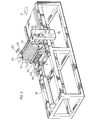
- FIG 3 in combination with Figures 4 and 5, the apparatus according to the present invention is shown for fabricating high fin density heatsinks, comprising a plurality of disks 7 mounted to an axle 9.
- the axle 9 is mounted for rotation in a pair of adjustable height mounting blocks 10.
- the disks are spaced apart a predetermined distance equivalent to the distance between successive ones of the plurality of grooves 5.
- the clearance between the lower most portion of the circumference of the disks 7 and the top of the working surface 11 ( Figure 8) is adjusted to be slightly less than the thickness of the base unit 1.
- each of the disks 7 has a width approximately equal to but no greater than the distance between successive ones of the plurality of grooves 5 minus the width of each of the fins 3.
- the working surface 11 which supports the base unit 1 while it passes beneath the disks 7 is, in turn, supported by a roller 16 mounted to a second axle 18 which is also mounted in blocks 10.
- the height of the axle 9, and hence the clearance between the disks 7 and working surface 11, may be adjusted by turning the handle 20 (Figure 3), which is connected to a rod 22 having a pair of geared wheels 24 (only one such wheel being shown in Figures 3 and 9).
- the wheels 24 engage respective cooperatively shaped wheels 26 each mounted to a further rod 28 (only one such wheel and rod being shown in Figures 3 and 9).
- Each rod 28 has, at an end opposite to the geared wheel 26, a threaded portion 29 ( Figure 3) which engages a gear wheel 30 of a threaded bolt member 32.
- the rod 22 rotates, causing rods 28 to rotate as a result of interaction between geared wheels 24 and 26. This, in turn, causes the gear 30 and threaded bolt 32 to rotate within mounting block 20.
- the axle 9 is housed within a riser block 34 which has internal threads for receiving the threaded bolt 32.
- the riser block 34 may be raised or lowered.
- one rotation of handle 20 results in a axle height adjustment of approximately of 2.5 x 10- 3 inches.
- FIG. 9 Also shown in Figure 9 is a pair of pneumatically controlled rollers 36 and 28 which are adapted to rest on top of the fins 3 as they pass through disks 7.
- the rollers 36 are required to securely hold down the fins 3 in the grooves 5 before pressure is applied during swaging.
- the rollers 38 are required to prevent the fins 3 from rolling upwardly and around the disks 7 after swaging.
- the fins are loosely placed in the grooves 5 of base unit 1.
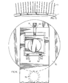
- the fins 3 are then aligned relative to the spaces between respective disks 7 by means of the alignment tool 12 shown in Figure 6.
- This tool comprises a plurality of teeth 14 spaced at equivalent intervals to the disks 7.
- the non-aligned positions of the fins 3 are shown in phantom.
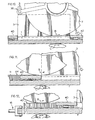
- the loosely assembled unit is then advanced into the apparatus of Figure 3 by means of a pneumatic drive 16, such that respective ones of the fins 3 pass between respective disks 7, as shown in Figure 4.
- a pneumatic drive 16 As the loosely assembled unit is advanced in the direction of arrow A in Figures 10, 11 and 12, the disks rotate in the direction of arrow B and the roller 16 rotates in the direction of arrow C, such that the lower most circumference portions of the disks 7 apply pressure to the regions of base unit 1 intermediate respective ones of the fins 3 for swaging the metal material in these regions to thereby crimp the fins 3 firmly in place.
- the pressure provided by the apparatus of Figure 3 on block 1 may be adjusted by careful selection of the height of the axle 9.
- each of the disks is shown comprising a raised circular hub portion 50 of predetermined thickness against which an adjacent one of the plurality of disks rests.
- the predetermined thickness of the raised circular hub portion defines the distance between respective ones of the disks 7.
- Each raised circular hub 50 has a keyway in the form of a rectangular slot 52 therein for receiving a cooperatively shaped rectangular key 54 projecting from the axle 9, in order to mount the disks 7 for rotation in conjunction with axle 9.
- the fins 3 often become displaced laterally with reference to the base unit 1. Therefore, according to the present invention, as shown in Figure 13, the heatsink is inverted and secured in a mounting device 60 and a rotary blade 62 is used to cut through the excess portions of the fins 3 for trimming such access portions off of the heatsink, in a straight forward manner.
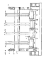
- axle block 74 the apparatus for de-warping the base unit 1 comprising a plurality of pairs of disks 70 mounted to axle 72 which, in turn, is housed in an axle block 74.
- the base unit 1 is supported from beneath by a plurality of sub-rollers (shown in phantom with reference numeral 76 in Figures 14 and 16).
- the diameter of the outer two disk pairs 78 is made less than the diameter of the inner two disk pairs 80 so that with base unit 1 supported on rollers 76, the inner disk pairs 80 exert a greater force on the center portion of the warped base 1 than outer disk pairs 78 forflatten- ing the warped base unit 1 from the position shown in solid lines to the flattened shape shown in phantom with reference to Figure 15.
- axle block 74 is shown supported from beneath by a pair of coil springs 92.
- the threaded bolt 71 controls the height of axle block 74 relative to the roller 76. More particularly, the bolt 71 is threaded into an internal threaded hole 90 and a portion of the bolt 71 contacts an upper portion of the axle block 74 for applying equal and opposite pressure to the coil springs 92.
- FIGs 17A-17D the various warped and de-warped shapes of the base unit 1 are shown schematically.
- the base unit 1 shown in its initial flat configuration.
- the base unit 1 is shown warped upwardly in the center as a result of the swaging operation discussed in greater detail above with reference to Figure 3.
- the shape of base unit 1 is illustrated schematically to show the pressure of disk 70 on the top surface thereof as the heat sink passes through the de-warping apparatus of Figure 14.
- Figure 17D shows the base unit 1 after de-warping, which is similar to the initial flat shape of the base unit 1.
- rollers 76 discussed above with reference to Figure 14 are shown in detail comprising a series of interconnected sub-rollers 82 positioned so as to provide a constant clearance D between respective ones of the pairs of disks 78 and 80 and the associated sub-rollers 82, for effecting the de-warping discussed above in connection with Figure 17C.
- the base unit 1 is flexed downwardly in the middle relative to the outer edges of the base unit 1, for de-warping the base unit.
- the method and apparatus of the present invention result in low cost fabrication of high fin ratio heatsinks, (eg. 6:1, 8:1, 10:1 and greater).
- the heatsinks are characterized by high thermal contact between the base unit and fins with no moisture or air therebetween, thus preventing corrosion and permitting the part to be anodized.
Landscapes
- Engineering & Computer Science (AREA)
- Thermal Sciences (AREA)
- Mechanical Engineering (AREA)
- General Engineering & Computer Science (AREA)
- Physics & Mathematics (AREA)
- Forging (AREA)
- Physical Or Chemical Processes And Apparatus (AREA)
- Surface Heating Bodies (AREA)
- Cooling Or The Like Of Electrical Apparatus (AREA)
- Injection Moulding Of Plastics Or The Like (AREA)
- Moulds For Moulding Plastics Or The Like (AREA)
- Straightening Metal Sheet-Like Bodies (AREA)
- Container, Conveyance, Adherence, Positioning, Of Wafer (AREA)
Priority Applications (1)
| Application Number | Priority Date | Filing Date | Title |
|---|---|---|---|
| EP01119895A EP1179840A1 (fr) | 1993-10-06 | 1994-09-19 | Méthode et appareil pour fabriquer des dissipateurs de chaleur à haute densité d'ailettes |
Applications Claiming Priority (2)
| Application Number | Priority Date | Filing Date | Title |
|---|---|---|---|
| CA2107869 | 1993-10-06 | ||
| CA002107869A CA2107869C (fr) | 1993-10-06 | 1993-10-06 | Methode et appareil de fabrication de dissipateurs de chaleur a ailettes haute densite |
Related Child Applications (1)
| Application Number | Title | Priority Date | Filing Date |
|---|---|---|---|
| EP01119895A Division EP1179840A1 (fr) | 1993-10-06 | 1994-09-19 | Méthode et appareil pour fabriquer des dissipateurs de chaleur à haute densité d'ailettes |
Publications (3)
| Publication Number | Publication Date |
|---|---|
| EP0650188A2 true EP0650188A2 (fr) | 1995-04-26 |
| EP0650188A3 EP0650188A3 (fr) | 1995-09-27 |
| EP0650188B1 EP0650188B1 (fr) | 2002-03-13 |
Family
ID=4152410
Family Applications (2)
| Application Number | Title | Priority Date | Filing Date |
|---|---|---|---|
| EP94306837A Expired - Lifetime EP0650188B1 (fr) | 1993-10-06 | 1994-09-19 | Méthode et appareil pour fabriquer des dissipateurs de chaleur à haute densité d'ailettes |
| EP01119895A Withdrawn EP1179840A1 (fr) | 1993-10-06 | 1994-09-19 | Méthode et appareil pour fabriquer des dissipateurs de chaleur à haute densité d'ailettes |
Family Applications After (1)
| Application Number | Title | Priority Date | Filing Date |
|---|---|---|---|
| EP01119895A Withdrawn EP1179840A1 (fr) | 1993-10-06 | 1994-09-19 | Méthode et appareil pour fabriquer des dissipateurs de chaleur à haute densité d'ailettes |
Country Status (8)
| Country | Link |
|---|---|
| US (2) | US5406698A (fr) |
| EP (2) | EP0650188B1 (fr) |
| AT (1) | ATE214519T1 (fr) |
| AU (2) | AU677412B2 (fr) |
| CA (2) | CA2107869C (fr) |
| DE (1) | DE69430096T2 (fr) |
| DK (1) | DK0650188T3 (fr) |
| ES (1) | ES2173907T3 (fr) |
Cited By (4)
| Publication number | Priority date | Publication date | Assignee | Title |
|---|---|---|---|---|
| DE19836314A1 (de) * | 1998-08-11 | 2000-02-24 | Joachim Bayer | Verfahren zur Herstellung von Kühlkörpern zum Anbau an Halbleiterbauelemente |
| WO2003019652A3 (fr) * | 2001-08-24 | 2003-08-14 | Bosch Gmbh Robert | Procede de fixation d'un element electrique et unite sur laquelle est fixe un element electrique |
| DE20309856U1 (de) * | 2003-06-24 | 2004-10-28 | Autokühler GmbH & Co. KG | Kühlkörper für Bauelemente |
| EP2204245A1 (fr) * | 2008-12-31 | 2010-07-07 | Rich Sphere Precision Industry Co., Ltd. | Procédé d'assemblage d'un dissipateur de chaleur |
Families Citing this family (34)
| Publication number | Priority date | Publication date | Assignee | Title |
|---|---|---|---|---|
| US5499450A (en) * | 1994-12-19 | 1996-03-19 | Jacoby; John | Method of manufacturing a multiple pin heatsink device |
| US5535515A (en) * | 1995-03-13 | 1996-07-16 | Jacoby; John | Method of manufacturing a stress-free heatsink assembly |
| US5819407A (en) * | 1995-04-19 | 1998-10-13 | Tousui, Ltd. | Method of joining together a pair of members each having a high thermal conductivity |
| US5771966A (en) * | 1995-12-15 | 1998-06-30 | Jacoby; John | Folded conducting member heatsinks and method of making same |
| JP3885197B2 (ja) * | 1997-04-11 | 2007-02-21 | 株式会社アルファ | 基板部に長孔を有する熱交換部品並びにその製造方法 |
| US6000132A (en) * | 1997-12-01 | 1999-12-14 | R-Theta Inc. | Method of forming heat dissipating fins |
| US6089781A (en) * | 1998-08-12 | 2000-07-18 | Hughes Electronics Corporation | Structure utilizing a shape-memory alloy fastener |
| TW556074B (en) * | 1998-12-15 | 2003-10-01 | Foxconn Prec Components Co Ltd | Heat sink and the manufacturing method thereof |
| US6202303B1 (en) | 1999-04-08 | 2001-03-20 | Intel Corporation | Method for producing high efficiency heat sinks |
| JP3760065B2 (ja) * | 1999-09-30 | 2006-03-29 | 山洋電気株式会社 | 冷却ファン装着型ヒートシンクの製造方法 |
| JP3552047B2 (ja) * | 2000-10-25 | 2004-08-11 | 古河電気工業株式会社 | ヒートシンク、その製造方法、および、押圧治具 |
| TW493368B (en) * | 2001-02-27 | 2002-07-01 | Delta Electronics Inc | Manufacturing method for heat sink having high density fin |
| TW535489B (en) * | 2002-05-31 | 2003-06-01 | Peng Jian | Composite working method of heat conduction device and the product thereof |
| US7497013B2 (en) * | 2005-04-15 | 2009-03-03 | R-Theta Thermal Solutions Inc. | Method and apparatus for coupling fins in a high-fin density heatsink to dual heat-dissipating base plates |
| US7420810B2 (en) * | 2006-09-12 | 2008-09-02 | Graftech International Holdings, Inc. | Base heat spreader with fins |
| US7592695B2 (en) | 2006-12-11 | 2009-09-22 | Graftech International Holdings Inc. | Compound heat sink |
| TW200934361A (en) * | 2008-01-16 | 2009-08-01 | Neng Tyi Prec Ind Co Ltd | Method of manufacturing heat dissipater and structure thereof |
| TW200934362A (en) * | 2008-01-16 | 2009-08-01 | Neng Tyi Prec Ind Co Ltd | Method of manufacturing heat dissipaters having heat sinks and structure thereof |
| JP4835807B2 (ja) * | 2009-05-22 | 2011-12-14 | トヨタ自動車株式会社 | 熱交換器及びその製造方法 |
| CN102832137A (zh) * | 2011-06-15 | 2012-12-19 | 富准精密工业(深圳)有限公司 | 散热装置的制造方法 |
| WO2014016219A1 (fr) | 2012-07-23 | 2014-01-30 | Basf Se | Polymères de dithiénobenzofurane et petites molécules pour application électronique |
| CN103418708B (zh) * | 2013-09-05 | 2015-08-12 | 美尔森电气保护系统(上海)有限公司 | 插片式风冷散热器的滚压工艺 |
| FR3036918B1 (fr) * | 2015-05-29 | 2018-08-10 | Thales | Carte electronique et procede de fabrication associe |
| CN109974334B (zh) * | 2017-12-27 | 2024-01-16 | 宁波方太厨具有限公司 | 一种风冷型半导体制冷装置 |
| US10612863B2 (en) * | 2018-05-06 | 2020-04-07 | Chaun-Choung Technology Corp. | Pressing method of heat conductive base and finished product thereof |
| CN112916744B (zh) * | 2019-12-05 | 2024-03-08 | 中兴通讯股份有限公司 | 散热器的制造方法 |
| JP7329775B2 (ja) * | 2019-12-23 | 2023-08-21 | パナソニックIpマネジメント株式会社 | レーザ装置の製造方法及びフィンブロックの製造方法 |
| CN111203456A (zh) * | 2020-04-17 | 2020-05-29 | 英利能源(镇江)有限公司 | 一种光伏焊带排版机用的整平装置 |
| CN112296122B (zh) * | 2020-10-14 | 2023-06-30 | 江苏隆达超合金股份有限公司 | 高翅片白铜合金高效管制造工艺 |
| US11330738B1 (en) | 2020-12-23 | 2022-05-10 | Xilinx, Inc. | Force balanced package mounting |
| US11605886B1 (en) | 2020-12-23 | 2023-03-14 | Xilinx, Inc. | Radome with integrated passive cooling |
| CN112845712A (zh) * | 2021-01-22 | 2021-05-28 | 江苏宏博机械制造有限公司 | 一种波纹管用钢板卷弧装置 |
| CN113399887B (zh) * | 2021-07-19 | 2023-03-21 | 沈阳天通电气有限公司 | 一种散热片的水平组装焊接连续生产方法 |
| CN116174531B (zh) * | 2023-02-23 | 2023-09-01 | 泉州吉隽科技有限公司 | 一种可防止倾斜的铝合金散热片矫直器 |
Family Cites Families (23)
| Publication number | Priority date | Publication date | Assignee | Title |
|---|---|---|---|---|
| US941375A (en) * | 1907-04-20 | 1909-11-30 | Westinghouse Machine Co | Turbine-blade. |
| DE513460C (de) * | 1926-08-06 | 1930-11-27 | Alfred J Berg | Werkzeug zum Befestigen einer schraubengangfoermigen Heizrippe auf einem Rohr |
| US1989059A (en) * | 1931-09-01 | 1935-01-22 | Republic Steel Corp | Tube forming roll |
| GB477590A (en) * | 1937-01-26 | 1938-01-03 | Metal Trim Ltd | Improvements in or relating to rollers for use in producing profiled sections from sheet metal |
| DE758524C (de) * | 1939-03-04 | 1953-03-09 | Hans Skodock Spezialfabrik Fue | Verfahren zur Herstellung eines biegsamen Schlauches mit in sich verlaufenden Querwellen |
| US2639119A (en) * | 1947-11-14 | 1953-05-19 | Lockheed Aircraft Corp | Rotor blade attachment means and method |
| US2944326A (en) * | 1955-06-02 | 1960-07-12 | Gen Electric | Method of staking blades |
| US3077928A (en) * | 1959-03-03 | 1963-02-19 | Baldwin Lima Hamilton Corp | Finned tubing |
| US3145758A (en) * | 1961-01-23 | 1964-08-25 | Mobile Pipe Corp | Apparatus for continuous forming of metal shapes |
| US3216496A (en) * | 1961-02-01 | 1965-11-09 | Astro Dynamics Inc | Heat sink for electronic devices |
| US3161944A (en) * | 1961-07-10 | 1964-12-22 | Calumet & Hecla | Combination fin-forming and fin-attaching methods and apparatus |
| US3261396A (en) * | 1963-11-13 | 1966-07-19 | Staver Co | Heat dissipator for electronic circuitry |
| US3280907A (en) * | 1964-09-01 | 1966-10-25 | Hoffman Sidney | Energy transfer device |
| US3312277A (en) * | 1965-03-22 | 1967-04-04 | Astrodyne Inc | Heat sink |
| DE1926750A1 (de) * | 1969-05-24 | 1970-12-23 | Demag Ag | Vorrichtung fuer die Formgebung von Schlitzroehren |
| JPS55112133A (en) * | 1979-02-21 | 1980-08-29 | Kawasaki Heavy Ind Ltd | Continuous bending machine |
| JPS5932213B2 (ja) * | 1981-06-22 | 1984-08-07 | 岩井金属工業株式会社 | 放熱板におけるフィンの固定方法 |
| DE3518310A1 (de) * | 1985-05-22 | 1986-11-27 | Aluminium-Walzwerke Singen Gmbh, 7700 Singen | Kuehlkoerper fuer halbleiterbauelemente und verfahren zu seiner herstellung |
| US4733453A (en) * | 1987-01-16 | 1988-03-29 | Pinfin, Inc. | Method of making a multiple-pin heatsink |
| SU1417951A1 (ru) * | 1987-01-22 | 1988-08-23 | Московский институт стали и сплавов | Формовочный стан трубоэлектросварочного агрегата |
| JPH07107490B2 (ja) * | 1988-09-16 | 1995-11-15 | 日本電装株式会社 | 光透過式の表示装置 |
| DE3940933C2 (de) * | 1989-12-12 | 1996-08-01 | Eupec Gmbh & Co Kg | Verfahren zum Verformen einer Basisplatte für Halbleitermodule und Vorrichtung zum Durchführen des Verfahrens |
| JPH06198383A (ja) * | 1992-09-21 | 1994-07-19 | Hideaki Serizawa | 放熱板及びその製作方法 |
-
1993
- 1993-10-06 CA CA002107869A patent/CA2107869C/fr not_active Expired - Lifetime
- 1993-10-06 CA CA002211562A patent/CA2211562C/fr not_active Expired - Lifetime
-
1994
- 1994-03-15 US US08/213,075 patent/US5406698A/en not_active Expired - Lifetime
- 1994-09-14 AU AU72968/94A patent/AU677412B2/en not_active Ceased
- 1994-09-19 DE DE69430096T patent/DE69430096T2/de not_active Expired - Lifetime
- 1994-09-19 DK DK94306837T patent/DK0650188T3/da active
- 1994-09-19 EP EP94306837A patent/EP0650188B1/fr not_active Expired - Lifetime
- 1994-09-19 AT AT94306837T patent/ATE214519T1/de active
- 1994-09-19 ES ES94306837T patent/ES2173907T3/es not_active Expired - Lifetime
- 1994-09-19 EP EP01119895A patent/EP1179840A1/fr not_active Withdrawn
-
1995
- 1995-02-02 US US08/382,801 patent/US5638715A/en not_active Expired - Lifetime
-
1997
- 1997-06-02 AU AU23736/97A patent/AU2373697A/en not_active Abandoned
Cited By (4)
| Publication number | Priority date | Publication date | Assignee | Title |
|---|---|---|---|---|
| DE19836314A1 (de) * | 1998-08-11 | 2000-02-24 | Joachim Bayer | Verfahren zur Herstellung von Kühlkörpern zum Anbau an Halbleiterbauelemente |
| WO2003019652A3 (fr) * | 2001-08-24 | 2003-08-14 | Bosch Gmbh Robert | Procede de fixation d'un element electrique et unite sur laquelle est fixe un element electrique |
| DE20309856U1 (de) * | 2003-06-24 | 2004-10-28 | Autokühler GmbH & Co. KG | Kühlkörper für Bauelemente |
| EP2204245A1 (fr) * | 2008-12-31 | 2010-07-07 | Rich Sphere Precision Industry Co., Ltd. | Procédé d'assemblage d'un dissipateur de chaleur |
Also Published As
| Publication number | Publication date |
|---|---|
| AU2373697A (en) | 1997-08-14 |
| ES2173907T3 (es) | 2002-11-01 |
| EP0650188A3 (fr) | 1995-09-27 |
| US5406698A (en) | 1995-04-18 |
| CA2107869A1 (fr) | 1995-04-07 |
| AU7296894A (en) | 1995-04-27 |
| US5638715A (en) | 1997-06-17 |
| EP0650188B1 (fr) | 2002-03-13 |
| CA2211562C (fr) | 2002-02-26 |
| EP1179840A1 (fr) | 2002-02-13 |
| CA2107869C (fr) | 1998-05-05 |
| AU677412B2 (en) | 1997-04-24 |
| DE69430096D1 (de) | 2002-04-18 |
| CA2211562A1 (fr) | 1995-04-07 |
| DK0650188T3 (da) | 2002-07-08 |
| ATE214519T1 (de) | 2002-03-15 |
| DE69430096T2 (de) | 2002-11-21 |
Similar Documents
| Publication | Publication Date | Title |
|---|---|---|
| US5406698A (en) | Apparatus for fabricating high fin density heatsinks | |
| US5421406A (en) | Heat sinks having pin-shaped fins and process for producing same | |
| US5558155A (en) | Cooling apparatus and assembling method thereof | |
| US7819173B2 (en) | Base plate for a dual base plate heatsink | |
| US6883592B2 (en) | Heatsink for electronic component | |
| AU745603B2 (en) | Heatsink for electronic component, and apparatus and method for manufacturing the same | |
| WO2020052829A1 (fr) | Procédé de fabrication d'une unité de module de puissance, unité de module de puissance, alimentation électrique et convertisseur de fréquence | |
| US6995981B2 (en) | Heat sink assembly with combined parallel fins | |
| JPH06198383A (ja) | 放熱板及びその製作方法 | |
| JPH07193383A (ja) | ヒートシンク及びその製造方法並びにその加工用治具 | |
| JPH1117080A (ja) | 放熱器 | |
| US3818568A (en) | Apparatus for forming heat exchangers | |
| JPS6123349A (ja) | 放熱器 | |
| JPH10107466A (ja) | ヒートシンクおよびその製造方法 | |
| JP2000151163A (ja) | ヒートシンクの製造法 | |
| JP4301593B2 (ja) | ヒートシンク用押出形材の矯正装置 | |
| JP4215927B2 (ja) | 電子部品の放熱器 | |
| JPH08317U (ja) | 半導体用ヒ−トパイプ冷却器 | |
| JPH0310695Y2 (fr) | ||
| JPH09155487A (ja) | 熱交換器用コルゲートフィンの成形方法 | |
| DE19700432A1 (de) | Verfahren zum Herstellen von Kühlkörpern sowie nach dem Verfahren hergestellte Kühlkörper | |
| JPS633199Y2 (fr) | ||
| JPH054496U (ja) | ヒートパイプ放熱用フイン挿入装置 | |
| JPH0214204Y2 (fr) | ||
| JPH0727158U (ja) | 半導体素子用放熱器 |
Legal Events
| Date | Code | Title | Description |
|---|---|---|---|
| PUAI | Public reference made under article 153(3) epc to a published international application that has entered the european phase |
Free format text: ORIGINAL CODE: 0009012 |
|
| AK | Designated contracting states |
Kind code of ref document: A2 Designated state(s): AT BE CH DE DK ES FR GB GR IE IT LI LU MC NL PT SE |
|
| RAX | Requested extension states of the european patent have changed |
Free format text: SI PAYMENT 941004 |
|
| PUAL | Search report despatched |
Free format text: ORIGINAL CODE: 0009013 |
|
| AK | Designated contracting states |
Kind code of ref document: A3 Designated state(s): AT BE CH DE DK ES FR GB GR IE IT LI LU MC NL PT SE |
|
| 17P | Request for examination filed |
Effective date: 19960228 |
|
| 17Q | First examination report despatched |
Effective date: 19970925 |
|
| GRAG | Despatch of communication of intention to grant |
Free format text: ORIGINAL CODE: EPIDOS AGRA |
|
| GRAG | Despatch of communication of intention to grant |
Free format text: ORIGINAL CODE: EPIDOS AGRA |
|
| GRAH | Despatch of communication of intention to grant a patent |
Free format text: ORIGINAL CODE: EPIDOS IGRA |
|
| GRAH | Despatch of communication of intention to grant a patent |
Free format text: ORIGINAL CODE: EPIDOS IGRA |
|
| REG | Reference to a national code |
Ref country code: GB Ref legal event code: IF02 |
|
| GRAA | (expected) grant |
Free format text: ORIGINAL CODE: 0009210 |
|
| AK | Designated contracting states |
Kind code of ref document: B1 Designated state(s): AT BE CH DE DK ES FR GB GR IE IT LI LU MC NL PT SE |
|
| AX | Request for extension of the european patent |
Free format text: SI PAYMENT 19941004 |
|
| PG25 | Lapsed in a contracting state [announced via postgrant information from national office to epo] |
Ref country code: GR Free format text: LAPSE BECAUSE OF FAILURE TO SUBMIT A TRANSLATION OF THE DESCRIPTION OR TO PAY THE FEE WITHIN THE PRESCRIBED TIME-LIMIT Effective date: 20020313 |
|
| REF | Corresponds to: |
Ref document number: 214519 Country of ref document: AT Date of ref document: 20020315 Kind code of ref document: T |
|
| REG | Reference to a national code |
Ref country code: CH Ref legal event code: EP |
|
| REF | Corresponds to: |
Ref document number: 69430096 Country of ref document: DE Date of ref document: 20020418 |
|
| PG25 | Lapsed in a contracting state [announced via postgrant information from national office to epo] |
Ref country code: PT Free format text: LAPSE BECAUSE OF FAILURE TO SUBMIT A TRANSLATION OF THE DESCRIPTION OR TO PAY THE FEE WITHIN THE PRESCRIBED TIME-LIMIT Effective date: 20020614 |
|
| REG | Reference to a national code |
Ref country code: DK Ref legal event code: T3 |
|
| REG | Reference to a national code |
Ref country code: CH Ref legal event code: NV Representative=s name: RITSCHER & PARTNER AG PATENTANWAELTE |
|
| ET | Fr: translation filed | ||
| PG25 | Lapsed in a contracting state [announced via postgrant information from national office to epo] |
Ref country code: LU Free format text: LAPSE BECAUSE OF NON-PAYMENT OF DUE FEES Effective date: 20020919 Ref country code: IE Free format text: LAPSE BECAUSE OF NON-PAYMENT OF DUE FEES Effective date: 20020919 |
|
| REG | Reference to a national code |
Ref country code: ES Ref legal event code: FG2A Ref document number: 2173907 Country of ref document: ES Kind code of ref document: T3 |
|
| PLBE | No opposition filed within time limit |
Free format text: ORIGINAL CODE: 0009261 |
|
| STAA | Information on the status of an ep patent application or granted ep patent |
Free format text: STATUS: NO OPPOSITION FILED WITHIN TIME LIMIT |
|
| 26N | No opposition filed |
Effective date: 20021216 |
|
| PG25 | Lapsed in a contracting state [announced via postgrant information from national office to epo] |
Ref country code: MC Free format text: LAPSE BECAUSE OF NON-PAYMENT OF DUE FEES Effective date: 20030401 |
|
| REG | Reference to a national code |
Ref country code: IE Ref legal event code: MM4A |
|
| REG | Reference to a national code |
Ref country code: CH Ref legal event code: PCAR Free format text: RITSCHER & PARTNER AG;RESIRAIN 1;8125 ZOLLIKERBERG (CH) |
|
| PG25 | Lapsed in a contracting state [announced via postgrant information from national office to epo] |
Ref country code: IT Free format text: LAPSE BECAUSE OF NON-PAYMENT OF DUE FEES Effective date: 20100919 |
|
| PGRI | Patent reinstated in contracting state [announced from national office to epo] |
Ref country code: IT Effective date: 20110616 |
|
| PGFP | Annual fee paid to national office [announced via postgrant information from national office to epo] |
Ref country code: ES Payment date: 20130926 Year of fee payment: 20 Ref country code: DE Payment date: 20130927 Year of fee payment: 20 Ref country code: NL Payment date: 20130926 Year of fee payment: 20 Ref country code: DK Payment date: 20130925 Year of fee payment: 20 Ref country code: AT Payment date: 20130903 Year of fee payment: 20 Ref country code: SE Payment date: 20130927 Year of fee payment: 20 |
|
| PGFP | Annual fee paid to national office [announced via postgrant information from national office to epo] |
Ref country code: GB Payment date: 20130927 Year of fee payment: 20 Ref country code: FR Payment date: 20130919 Year of fee payment: 20 |
|
| REG | Reference to a national code |
Ref country code: CH Ref legal event code: PFA Owner name: R-THETA INC., CA Free format text: FORMER OWNER: R-THETA INC., CA |
|
| PGFP | Annual fee paid to national office [announced via postgrant information from national office to epo] |
Ref country code: IT Payment date: 20130924 Year of fee payment: 20 |
|
| PGFP | Annual fee paid to national office [announced via postgrant information from national office to epo] |
Ref country code: BE Payment date: 20130927 Year of fee payment: 20 Ref country code: CH Payment date: 20130927 Year of fee payment: 20 |
|
| REG | Reference to a national code |
Ref country code: DE Ref legal event code: R071 Ref document number: 69430096 Country of ref document: DE |
|
| REG | Reference to a national code |
Ref country code: DK Ref legal event code: EUP Effective date: 20140919 |
|
| REG | Reference to a national code |
Ref country code: NL Ref legal event code: V4 Effective date: 20140919 |
|
| REG | Reference to a national code |
Ref country code: CH Ref legal event code: PL |
|
| REG | Reference to a national code |
Ref country code: GB Ref legal event code: PE20 Expiry date: 20140918 |
|
| PG25 | Lapsed in a contracting state [announced via postgrant information from national office to epo] |
Ref country code: DE Free format text: LAPSE BECAUSE OF EXPIRATION OF PROTECTION Effective date: 20140920 |
|
| REG | Reference to a national code |
Ref country code: SE Ref legal event code: EUG |
|
| REG | Reference to a national code |
Ref country code: AT Ref legal event code: MK07 Ref document number: 214519 Country of ref document: AT Kind code of ref document: T Effective date: 20140919 |
|
| PG25 | Lapsed in a contracting state [announced via postgrant information from national office to epo] |
Ref country code: GB Free format text: LAPSE BECAUSE OF EXPIRATION OF PROTECTION Effective date: 20140918 |
|
| REG | Reference to a national code |
Ref country code: ES Ref legal event code: FD2A Effective date: 20150108 |
|
| PG25 | Lapsed in a contracting state [announced via postgrant information from national office to epo] |
Ref country code: ES Free format text: LAPSE BECAUSE OF EXPIRATION OF PROTECTION Effective date: 20140920 |