EP0650845A2 - Alimentation des supports d'impression et mécanisme d'avance du chariot pour imprimantes à navette - Google Patents
Alimentation des supports d'impression et mécanisme d'avance du chariot pour imprimantes à navette Download PDFInfo
- Publication number
- EP0650845A2 EP0650845A2 EP94307825A EP94307825A EP0650845A2 EP 0650845 A2 EP0650845 A2 EP 0650845A2 EP 94307825 A EP94307825 A EP 94307825A EP 94307825 A EP94307825 A EP 94307825A EP 0650845 A2 EP0650845 A2 EP 0650845A2
- Authority
- EP
- European Patent Office
- Prior art keywords
- carriage
- media
- indexing
- wheel
- slot
- Prior art date
- Legal status (The legal status is an assumption and is not a legal conclusion. Google has not performed a legal analysis and makes no representation as to the accuracy of the status listed.)
- Withdrawn
Links
Images

Classifications
-
- B—PERFORMING OPERATIONS; TRANSPORTING
- B41—PRINTING; LINING MACHINES; TYPEWRITERS; STAMPS
- B41J—TYPEWRITERS; SELECTIVE PRINTING MECHANISMS, i.e. MECHANISMS PRINTING OTHERWISE THAN FROM A FORME; CORRECTION OF TYPOGRAPHICAL ERRORS
- B41J19/00—Character- or line-spacing mechanisms
- B41J19/18—Character-spacing or back-spacing mechanisms; Carriage return or release devices therefor
- B41J19/20—Positive-feed character-spacing mechanisms
-
- B—PERFORMING OPERATIONS; TRANSPORTING
- B41—PRINTING; LINING MACHINES; TYPEWRITERS; STAMPS
- B41J—TYPEWRITERS; SELECTIVE PRINTING MECHANISMS, i.e. MECHANISMS PRINTING OTHERWISE THAN FROM A FORME; CORRECTION OF TYPOGRAPHICAL ERRORS
- B41J19/00—Character- or line-spacing mechanisms
- B41J19/76—Line-spacing mechanisms
- B41J19/78—Positive-feed mechanisms
- B41J19/94—Positive-feed mechanisms automatically operated in response to carriage return
-
- B—PERFORMING OPERATIONS; TRANSPORTING
- B41—PRINTING; LINING MACHINES; TYPEWRITERS; STAMPS
- B41J—TYPEWRITERS; SELECTIVE PRINTING MECHANISMS, i.e. MECHANISMS PRINTING OTHERWISE THAN FROM A FORME; CORRECTION OF TYPOGRAPHICAL ERRORS
- B41J23/00—Power drives for actions or mechanisms
- B41J23/02—Mechanical power drives
- B41J23/025—Mechanical power drives using a single or common power source for two or more functions
Definitions
- This invention relates to shuttle-type printers.
- Shuttle-type printers are a class of printers having a movable shuttle or carriage that traverses back and forth across a printing surface. A printhead is mounted on the carriage and synchronized with carriage movement to print desired images.
- the shuttle class of printers includes both impact printers, such as dot matrix and daisy-wheel printers, and non-impact printers, such as ink-jet printers.
- Conventional shuttle-type printers have a media feed assembly which advances a recording media through the printer and a separate shuttle drive assembly which maneuvers the carriage over the recording media.
- the media feed assembly typically consists of friction rollers or a tractor feed mechanism and a motor coupled to rotate them.
- the shuttle drive assembly typically consists of a motor and a belt and pulley assembly which connects the carriage to the motor.
- Common motors used in these assemblies include DC motors which change speed and direction in relation to the level and polarity of DC voltage applied thereto, and stepper motors which change speed and direction in response to intermittent pulses.
- the two motors used for the media feed and shuttle drive assemblies are controlled in a synchronized manner.
- the carriage motor drives the carriage back and forth over the media in periodic swaths.
- the media feed motor increments the recording media within the printer to the next line.
- Special control circuitry is employed to synchronize the operation of these two motors.
- a problem of prior shuttle-type printers concerns the complexity of controlling the independent operation of the media feed motor and the carriage motor. Sophisticated hardware and firmware are necessary to manage both motors. In addition to the cost of each motor, there are extra costs resulting from multiple connectors, logic boards, and cables needed to operate both motors, as well as added power supply requirements.
- This invention overcomes the above problem by providing a mechanism for simultaneously moving the carriage and indexing the media by using a single motor.
- the mechanism thereby eliminates one motor and its associated logic board, connector, cable, and power supply overhead.
- a mechanism for a shuttle-type printer has a media feed assembly to controllably transfer a recording media through a printing station and a carriage operably mounted at the printing station to move bidirectionally across the media.
- the unique mechanism for use in the shuttle-type printer includes an indexing means for controllably advancing the recording media through the printing station to position the media relative to the carriage.
- the indexing means has first and second complementary components that mechanically mate to incrementally move the media.
- the first complementary component is provided on the media feed assembly and the second complementary component is provided on the carriage.
- a single drive means is operably connected to the carriage for simultaneously (1) moving the carriage to enable the first and second complementary components to mate, and (2) indexing the media through the printing station when the first and second complementary components mechanically mate.
- the mechanism includes a rotatable axle connected to the media feed assembly, whereby the axle defines a longitudinal axis.
- a slotted indexing wheel having at least one slot is mounted on the axle.
- a stationary elongated rod is provided a spaced distance from the axle and a carriage is slidably mounted to the rod to move bidirectionally along the rod and within an actuating proximity relative to the indexing wheel.
- the mechanism further includes a peg operably mounted on the carriage and dimensioned to slide within the slot of the indexing wheel.
- a motor is mechanically coupled to the carriage to simultaneously (1) drive the carriage bidirectionally along the rod and within the actuating proximity relative to the indexing wheel, and (2) rotate the axle a selected distance by moving the carriage mounted peg through the slot on the indexing wheel when the carriage is within the actuating proximity of the indexing wheel.
- the peg is pivotally mounted to the carriage.
- the peg is supported in an extended position to slide through the slot and rotate the slotted indexing wheel when the carriage is moved in one direction relative to the indexing wheel. Then, the peg pivots to a retracted position to avoid the slot when the carriage is moved in an opposite direction relative to the indexing wheel.
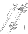
- Fig. 1 is a diagrammatic front view of a mechanism for a shuttle-type printer according to this invention.
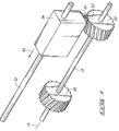
- Fig. 2 is a diagrammatic isometric view of the Fig. 1 mechanism illustrating the mechanism at a first operable position.
- Fig. 3 is a diagrammatic isometric view of the Fig. 1 mechanism illustrating the mechanism at a second operable position subsequent to the position of Fig. 2.
- This invention relates to a shuttle-type printer having a media feed assembly and a shuttle assembly.
- the media feed assembly controllably transfers a recording media sequentially from an initial storage station, through a printing station where text or images are formed on the media, and to a holding station.
- the shuttle assembly has a printhead supporting carriage mounted at the printing station to move bidirectionally across the media. As the carriage moves, the printhead prints images on the recording media.
- FIG. 1 shows a media feed and carriage motion mechanism 10 employed in a shuttle-type printer of this invention.
- Mechanism 10 includes a rotatable axle 12 aligned along a longitudinal axis 14.
- the rotatable axle 12 is mechanically coupled to a media advancement subassembly 16, such as a pair of friction rollers or a tractor feed system, which together form the mechanical components of a media feed assembly 18.
- a media advancement subassembly 16 moves the recording media through the shuttle-type printer along a media feed path (defined by dashed boundary lines 19).
- the media may be a continuous form or individual sheet stock, and can consist of paper, adhesive-backed labels, or other types of printable matter.
- Mechanism 10 also includes a first slotted indexing wheel 20 fixedly mounted on the left end of axle 12 and a second slotted indexing wheel 22 fixedly- mounted on the right end of axle 12. Wheels 20 and 22 are mounted a spaced relationship from one another and preferably positioned outside of media feed path 19. Slotted indexing wheels 20 and 22 have at least one, and preferably multiple, slots 23 formed therein. Most preferably, indexing wheels 20 and 22 are embodied as helical wheels having slots that follow helical paths twisting about axis 14. The orientation of the helical wheels are reversed, for reasons that become apparent from the continuing discussion, as the helical paths wind in opposing directions about the axis 14.
- Media feed and carriage motion mechanism 10 has a stationary elongated rod 32 spaced from axle 12 and a carriage 34 slidably mounted to the rod 32 to move bidirectionally over the media.
- Carriage 34 maneuvers over the full width of the rod to be positionable over central media feed path 19 and within actuating proximity with each of the indexing wheels 20 and 22.
- Carriage 34 has a nose section 36 that is adjacent to, but spaced from, a platen (not shown), whereby the recording media passes through a small gap between the nose section and the platen.
- a printhead (not shown) is mounted in the carriage 34 and oriented to position its print elements at the nose section and facing the platen/media.
- the printhead can be embodied as an ink-jet printhead, a dot matrix printhead, a daisy-wheel, a thermal transfer printhead, or any other type of printhead carried on a shuttle.
- a single drive means 38 is mechanically coupled to move carriage 34 back and forth along rod 32.
- Drive means 38 includes a wire or belt 40 attached to carriage 34 and wound around opposing pulleys 42, and a motor 44 connected to power one of the pulleys.
- Motor 44 can be a stepper motor or a DC motor.
- the single drive means is illustrated in its preferred form as having a belt and pulley system, but other configurations may be used.
- the single drive means may comprise a motor coupled to an elongated screw-type coupling, or as another example, a motor mounted within carriage 34.
- the rod 32, carriage 34, and drive means 38 comprise the primary components of the shuttle assembly of the printer.
- Mechanism 10 includes first and second pegs 50 and 52 mounted to opposing sides of carriage 34.
- the pegs are connected to pivot about their associated axles 50a and 52a.
- Pegs 50, 52 are pivotally held within support members 54 and 56, respectively, provided on nose section 36 of carriage 34.
- Pegs 50, 52 swing freely through a 90° arc (represented by arrow 57) from an extended, approximately vertical position (as shown by the left peg 50) to a retracted, approximately horizontal position.
- the pegs normally lie in their extended positions under the force of gravity.
- the pegs 50 and 52 In their extended position, the pegs 50 and 52 operatively engage corresponding indexing wheels 20 and 22 when the carriage 34 is moved over the wheels.
- the pegs are dimensioned to slide through the slots 23.
- Figs. 2 and 3 show the interaction of the pegs and indexing wheels in more detail.
- peg 52 As carriage 34 completes a swath across the media in the rightward direction (as represented by arrow 60), peg 52 is in its normal extended position as it engages a slot 23. Peg 52 is held in this position by retaining wall 58 of support member 56 (Fig. 1). As carriage 34 continues movement in the rightward direction, peg 52 matingly slides through slot 23 and causes indexing wheel 22 to rotate in a counterclockwise direction about axis 14 (as represented by arrow 64). The force exerted on peg 52 by retaining wall 58 counteracts the inertial and frictional forces imposed by the axle and media feed assembly.
- Wheel 22 and axle 12 are rotated a distance equivalent to the offset amount between the entrance and exit of slot 23.
- this rotational distance correlates to indexing a single line of media through the printing station relative to the carriage and printhead for the return swath of the carriage.
- the peg 52 and helical wheel 22 form an indexing means for controllably advancing the recording media through the printing station to position the media relative to the carriage.
- peg 50 When the carriage 34 reaches the left side indexing wheel 20, peg 50 mates with a slot 23 and causes the wheel and axle to rotate the prescribed distance as the carriage continues leftward. Then, when the carriage shifts again to the right (arrow 60 in Fig. 2), the peg 50 freely swings upward to an non-engagement position and does not induce the left side indexing wheel 20 to rotate.
- the reverse pattern of the helical grooves on slotted indexing wheels 20 and 22 enable the mechanism to advance the media in the same direction upon each carriage swath.
- helical slots could be reversed and the pegs designed to remain vertical when moving inward across the indexing wheels, as opposed to outward, to rotate the axle and advance the media.
- Other variations are also possible which are within the purview of a person skilled in the art.
- a single drive motor 44 is used to simultaneously (1) move the carriage bidirectionally along rod 32 over the recording media and helical wheels 20, 22 and (2) index the media through the printing station by causing the pegs 50, 52 to mechanically interface with the helical wheels 20, 22.
- This structure is advantageous over prior art shuttle-type printers because it eliminates one motor and the associated cable, connector, and logic board. This simplification significantly reduces costs as well as reducing operating complexity. The invention is therefore well suited for incorporation to low-cost, reliable shuttle-type printers.
- the preferred embodiment is described as employing a helical wheel and a pivotal peg.
- the helical wheel and peg form an indexing means having first and second complementary components that mechanically mate to incrementally move the recording media (via rotating axle 12).
- Other complementary components may be used to form the indexing means, however, with a first complementary component being provided on the media feed assembly and the second complementary component being provided on the carriage.
- complementary toothed gears could be used to achieve the indexing rotation.
Landscapes
- Common Mechanisms (AREA)
- Handling Of Sheets (AREA)
- Character Spaces And Line Spaces In Printers (AREA)
Applications Claiming Priority (2)
| Application Number | Priority Date | Filing Date | Title |
|---|---|---|---|
| US145020 | 1993-10-29 | ||
| US08/145,020 US5433543A (en) | 1993-10-29 | 1993-10-29 | Media feed and carriage motion mechanism for shuttle-type printers |
Publications (2)
| Publication Number | Publication Date |
|---|---|
| EP0650845A2 true EP0650845A2 (fr) | 1995-05-03 |
| EP0650845A3 EP0650845A3 (fr) | 1997-02-19 |
Family
ID=22511243
Family Applications (1)
| Application Number | Title | Priority Date | Filing Date |
|---|---|---|---|
| EP94307825A Withdrawn EP0650845A3 (fr) | 1993-10-29 | 1994-10-25 | Alimentation des supports d'impression et mécanisme d'avance du chariot pour imprimantes à navette. |
Country Status (3)
| Country | Link |
|---|---|
| US (1) | US5433543A (fr) |
| EP (1) | EP0650845A3 (fr) |
| JP (1) | JP3532637B2 (fr) |
Cited By (3)
| Publication number | Priority date | Publication date | Assignee | Title |
|---|---|---|---|---|
| EP0945763A1 (fr) * | 1998-03-27 | 1999-09-29 | Seiko Instruments Inc. | Dispositif d'impression utilisant des microcapsules photosensibles et système de traitement d'image utilisant ledit dispositif. |
| EP1270244A1 (fr) * | 2001-06-25 | 2003-01-02 | Seiko Epson Corporation | Imprimante |
| EP2902975A1 (fr) | 2014-01-31 | 2015-08-05 | Neopost Technologies | Machine postale de bureau d'entrée de gamme |
Families Citing this family (5)
| Publication number | Priority date | Publication date | Assignee | Title |
|---|---|---|---|---|
| JP3166998B2 (ja) * | 1994-02-08 | 2001-05-14 | キヤノン株式会社 | 記録装置及び記録制御方法 |
| US6123472A (en) * | 1999-03-29 | 2000-09-26 | Hewlett-Packard Company | Indexing stop for a printer carriage |
| JP5648441B2 (ja) * | 2010-11-24 | 2015-01-07 | 株式会社リコー | インクジェット記録装置 |
| JP5817010B1 (ja) * | 2014-11-05 | 2015-11-18 | 二郎 工藤 | カラーインクジェットラベルプリンター |
| JP6508720B2 (ja) * | 2015-08-31 | 2019-05-08 | セイコーソリューションズ株式会社 | 印字ユニット及びプリンタ |
Family Cites Families (13)
| Publication number | Priority date | Publication date | Assignee | Title |
|---|---|---|---|---|
| US4050569A (en) * | 1976-06-04 | 1977-09-27 | Ncr Corporation | Record media advancing mechanism |
| GB2046177B (en) * | 1979-03-26 | 1983-04-20 | Seiko Instr & Electronics | Printer |
| FR2498524B1 (fr) * | 1981-01-27 | 1986-07-25 | Thomson Csf | Dispositif electromecanique d'impression pour imprimante du type serie-parallele et telecopieur comportant un tel dispositif |
| US4402620A (en) * | 1981-12-23 | 1983-09-06 | International Business Machines Corp. | Compact shuttle printer mechanism |
| JPS6068985A (ja) * | 1983-09-27 | 1985-04-19 | Seiko Epson Corp | 紙送り機構 |
| JPS6178656A (ja) * | 1984-09-26 | 1986-04-22 | Canon Inc | 記録装置 |
| JPS61149386A (ja) * | 1984-12-25 | 1986-07-08 | Sharp Corp | プリンタの用紙送り装置 |
| EP0274266B1 (fr) * | 1986-12-27 | 1993-07-28 | Canon Kabushiki Kaisha | Dispositif à transmissions pour entraînements par moteur pour appareil d'enregistrement |
| JPS63212571A (ja) * | 1987-03-02 | 1988-09-05 | Tohoku Ricoh Co Ltd | シリアル印字装置の用紙送り機構 |
| DE3815066C1 (fr) * | 1988-05-04 | 1989-06-15 | Ta Triumph-Adler Ag, 8500 Nuernberg, De | |
| US5000594A (en) * | 1989-10-13 | 1991-03-19 | Hewlett-Packard Company | Printer with carriage-actuated clutch and paper-feed mechanism |
| US5153738A (en) * | 1991-05-20 | 1992-10-06 | Xerox Corporation | Scanner with single source mechanical power |
| US5269613A (en) * | 1992-09-29 | 1993-12-14 | Hewlett-Packard Company | Paper handling system for printers |
-
1993
- 1993-10-29 US US08/145,020 patent/US5433543A/en not_active Expired - Lifetime
-
1994
- 1994-10-25 EP EP94307825A patent/EP0650845A3/fr not_active Withdrawn
- 1994-10-28 JP JP28925794A patent/JP3532637B2/ja not_active Expired - Lifetime
Cited By (5)
| Publication number | Priority date | Publication date | Assignee | Title |
|---|---|---|---|---|
| EP0945763A1 (fr) * | 1998-03-27 | 1999-09-29 | Seiko Instruments Inc. | Dispositif d'impression utilisant des microcapsules photosensibles et système de traitement d'image utilisant ledit dispositif. |
| US6204914B1 (en) | 1998-03-27 | 2001-03-20 | Seiko Instruments Inc. | Printing apparatus of photosensitive microcapsule type and image processing system using the same |
| EP1270244A1 (fr) * | 2001-06-25 | 2003-01-02 | Seiko Epson Corporation | Imprimante |
| US6789968B2 (en) | 2001-06-25 | 2004-09-14 | Seiko Epson Corporation | Printer having a selector associated with a carriage for actuating a plurality of switching mechanisms |
| EP2902975A1 (fr) | 2014-01-31 | 2015-08-05 | Neopost Technologies | Machine postale de bureau d'entrée de gamme |
Also Published As
| Publication number | Publication date |
|---|---|
| US5433543A (en) | 1995-07-18 |
| EP0650845A3 (fr) | 1997-02-19 |
| JPH07186487A (ja) | 1995-07-25 |
| JP3532637B2 (ja) | 2004-05-31 |
Similar Documents
| Publication | Publication Date | Title |
|---|---|---|
| EP0571804B1 (fr) | Imprimante par jet d'encre multi-têtes | |
| US6155680A (en) | Ink-jet printer with stationary pens and two-axis media drive | |
| US5433543A (en) | Media feed and carriage motion mechanism for shuttle-type printers | |
| DE2819758A1 (de) | Schlagloser serien-parallel- oder parallel-punktmatrixdrucker | |
| EP0105472B1 (fr) | Imprimante thermique | |
| US4611937A (en) | Ribbon feed mechanism for a printer | |
| US6250754B1 (en) | Duplex printer | |
| US4375923A (en) | Rotatable print head for a multiple print station printing apparatus | |
| DE69433143T2 (de) | Apparat zum Drucken von Videobildern | |
| US5651620A (en) | Nonimpact printer having selectable ribbons and print heads | |
| US4761664A (en) | Print media handling system for compact printer with traversing, multiple print head carriage | |
| US4984914A (en) | Multi-task printer | |
| EP0359580B1 (fr) | Imprimante | |
| DE69016807T2 (de) | Verfahren und Apparat zur Aufzeichung. | |
| JPS60190380A (ja) | 熱転写プリンタ | |
| CN1948016A (zh) | 具有移动式打印头的打印机 | |
| RU2074822C1 (ru) | Печатающее устройство | |
| DE60201469T2 (de) | Drucker | |
| US4242005A (en) | Inked ribbon advance and reverse mechanism including a pawl having different size teeth | |
| JPH0768815A (ja) | プリント方法及び装置 | |
| US4381155A (en) | Inked ribbon advance and reverse mechanism | |
| JP3015681B2 (ja) | プリンタ | |
| JPH0890868A (ja) | 転写式プリンタ | |
| JPS58104763A (ja) | 印字装置 | |
| JPH0530186B2 (fr) |
Legal Events
| Date | Code | Title | Description |
|---|---|---|---|
| PUAI | Public reference made under article 153(3) epc to a published international application that has entered the european phase |
Free format text: ORIGINAL CODE: 0009012 |
|
| AK | Designated contracting states |
Kind code of ref document: A2 Designated state(s): DE FR GB IT |
|
| PUAL | Search report despatched |
Free format text: ORIGINAL CODE: 0009013 |
|
| AK | Designated contracting states |
Kind code of ref document: A3 Designated state(s): DE FR GB IT |
|
| 17P | Request for examination filed |
Effective date: 19970430 |
|
| 17Q | First examination report despatched |
Effective date: 19980324 |
|
| STAA | Information on the status of an ep patent application or granted ep patent |
Free format text: STATUS: THE APPLICATION IS DEEMED TO BE WITHDRAWN |
|
| 18D | Application deemed to be withdrawn |
Effective date: 20000503 |