EP0650905B1 - Emballage pour four à micro-ondes avec fonction pour régler l'adaptation de l'impédance - Google Patents
Emballage pour four à micro-ondes avec fonction pour régler l'adaptation de l'impédance Download PDFInfo
- Publication number
- EP0650905B1 EP0650905B1 EP94116521A EP94116521A EP0650905B1 EP 0650905 B1 EP0650905 B1 EP 0650905B1 EP 94116521 A EP94116521 A EP 94116521A EP 94116521 A EP94116521 A EP 94116521A EP 0650905 B1 EP0650905 B1 EP 0650905B1
- Authority
- EP
- European Patent Office
- Prior art keywords
- impedance matching
- package
- food
- film
- microwave energy
- Prior art date
- Legal status (The legal status is an assumption and is not a legal conclusion. Google has not performed a legal analysis and makes no representation as to the accuracy of the status listed.)
- Expired - Lifetime
Links
- 238000010411 cooking Methods 0.000 title description 17
- 235000013305 food Nutrition 0.000 claims abstract description 104
- 239000011230 binding agent Substances 0.000 claims abstract description 40
- 238000010438 heat treatment Methods 0.000 claims abstract description 30
- 230000001419 dependent effect Effects 0.000 claims abstract description 3
- 238000005304 joining Methods 0.000 claims abstract description 3
- XAGFODPZIPBFFR-UHFFFAOYSA-N aluminium Chemical compound [Al] XAGFODPZIPBFFR-UHFFFAOYSA-N 0.000 claims description 64
- 229910052782 aluminium Inorganic materials 0.000 claims description 59
- 238000000576 coating method Methods 0.000 claims description 21
- 239000011248 coating agent Substances 0.000 claims description 14
- 229910052751 metal Inorganic materials 0.000 claims description 11
- 239000002184 metal Substances 0.000 claims description 11
- 239000000758 substrate Substances 0.000 claims description 11
- 239000000123 paper Substances 0.000 claims description 8
- 239000011087 paperboard Substances 0.000 claims description 7
- 239000002131 composite material Substances 0.000 claims description 6
- 230000003287 optical effect Effects 0.000 claims description 6
- 239000007769 metal material Substances 0.000 claims description 3
- 238000000151 deposition Methods 0.000 claims description 2
- 239000004411 aluminium Substances 0.000 claims 2
- 239000002985 plastic film Substances 0.000 claims 1
- 229920006255 plastic film Polymers 0.000 claims 1
- 239000000463 material Substances 0.000 abstract description 54
- 239000010408 film Substances 0.000 description 86
- YXFVVABEGXRONW-UHFFFAOYSA-N Toluene Chemical compound CC1=CC=CC=C1 YXFVVABEGXRONW-UHFFFAOYSA-N 0.000 description 54
- 239000007787 solid Substances 0.000 description 31
- 239000000203 mixture Substances 0.000 description 30
- 235000015108 pies Nutrition 0.000 description 24
- XEKOWRVHYACXOJ-UHFFFAOYSA-N Ethyl acetate Chemical compound CCOC(C)=O XEKOWRVHYACXOJ-UHFFFAOYSA-N 0.000 description 21
- 238000012360 testing method Methods 0.000 description 21
- 230000005855 radiation Effects 0.000 description 19
- 238000009472 formulation Methods 0.000 description 17
- YKYONYBAUNKHLG-UHFFFAOYSA-N propyl acetate Chemical compound CCCOC(C)=O YKYONYBAUNKHLG-UHFFFAOYSA-N 0.000 description 14
- XLYOFNOQVPJJNP-UHFFFAOYSA-N water Substances O XLYOFNOQVPJJNP-UHFFFAOYSA-N 0.000 description 13
- 238000010521 absorption reaction Methods 0.000 description 11
- 239000001856 Ethyl cellulose Substances 0.000 description 10
- ZZSNKZQZMQGXPY-UHFFFAOYSA-N Ethyl cellulose Chemical compound CCOCC1OC(OC)C(OCC)C(OCC)C1OC1C(O)C(O)C(OC)C(CO)O1 ZZSNKZQZMQGXPY-UHFFFAOYSA-N 0.000 description 10
- 230000000694 effects Effects 0.000 description 10
- 235000019325 ethyl cellulose Nutrition 0.000 description 10
- 229920001249 ethyl cellulose Polymers 0.000 description 10
- KFZMGEQAYNKOFK-UHFFFAOYSA-N Isopropanol Chemical compound CC(C)O KFZMGEQAYNKOFK-UHFFFAOYSA-N 0.000 description 9
- 229920002050 silicone resin Polymers 0.000 description 9
- 238000000926 separation method Methods 0.000 description 8
- 239000011888 foil Substances 0.000 description 6
- 230000002452 interceptive effect Effects 0.000 description 6
- 238000000034 method Methods 0.000 description 6
- 241001137251 Corvidae Species 0.000 description 5
- 239000004594 Masterbatch (MB) Substances 0.000 description 5
- 230000005540 biological transmission Effects 0.000 description 5
- 239000006185 dispersion Substances 0.000 description 5
- 239000002245 particle Substances 0.000 description 5
- 239000010409 thin film Substances 0.000 description 5
- 229920002799 BoPET Polymers 0.000 description 4
- 230000007423 decrease Effects 0.000 description 4
- 235000013399 edible fruits Nutrition 0.000 description 4
- 239000010410 layer Substances 0.000 description 4
- 238000002156 mixing Methods 0.000 description 4
- 229920001296 polysiloxane Polymers 0.000 description 4
- 239000000523 sample Substances 0.000 description 4
- 241000287828 Gallus gallus Species 0.000 description 3
- 238000002835 absorbance Methods 0.000 description 3
- 230000000051 modifying effect Effects 0.000 description 3
- 238000004806 packaging method and process Methods 0.000 description 3
- 230000010363 phase shift Effects 0.000 description 3
- 229920006267 polyester film Polymers 0.000 description 3
- 229920000178 Acrylic resin Polymers 0.000 description 2
- 239000004925 Acrylic resin Substances 0.000 description 2
- 229920005692 JONCRYL® Polymers 0.000 description 2
- PPBRXRYQALVLMV-UHFFFAOYSA-N Styrene Chemical compound C=CC1=CC=CC=C1 PPBRXRYQALVLMV-UHFFFAOYSA-N 0.000 description 2
- 229920005822 acrylic binder Polymers 0.000 description 2
- 239000012790 adhesive layer Substances 0.000 description 2
- 239000008199 coating composition Substances 0.000 description 2
- 238000013461 design Methods 0.000 description 2
- 235000021158 dinner Nutrition 0.000 description 2
- 238000009826 distribution Methods 0.000 description 2
- 230000005684 electric field Effects 0.000 description 2
- 238000004519 manufacturing process Methods 0.000 description 2
- 239000011159 matrix material Substances 0.000 description 2
- 238000005259 measurement Methods 0.000 description 2
- 239000004033 plastic Substances 0.000 description 2
- 229920003023 plastic Polymers 0.000 description 2
- 229920000728 polyester Polymers 0.000 description 2
- 238000007639 printing Methods 0.000 description 2
- 230000008569 process Effects 0.000 description 2
- 230000002829 reductive effect Effects 0.000 description 2
- 229920005989 resin Polymers 0.000 description 2
- 239000011347 resin Substances 0.000 description 2
- 239000002344 surface layer Substances 0.000 description 2
- 238000012546 transfer Methods 0.000 description 2
- 238000002834 transmittance Methods 0.000 description 2
- 239000012780 transparent material Substances 0.000 description 2
- 238000007740 vapor deposition Methods 0.000 description 2
- 239000000020 Nitrocellulose Substances 0.000 description 1
- NIXOWILDQLNWCW-UHFFFAOYSA-N acrylic acid group Chemical group C(C=C)(=O)O NIXOWILDQLNWCW-UHFFFAOYSA-N 0.000 description 1
- 229920006397 acrylic thermoplastic Polymers 0.000 description 1
- 238000009835 boiling Methods 0.000 description 1
- 239000003990 capacitor Substances 0.000 description 1
- 230000008859 change Effects 0.000 description 1
- 239000012141 concentrate Substances 0.000 description 1
- 230000003247 decreasing effect Effects 0.000 description 1
- 230000001627 detrimental effect Effects 0.000 description 1
- 238000011161 development Methods 0.000 description 1
- 238000002474 experimental method Methods 0.000 description 1
- 239000007888 film coating Substances 0.000 description 1
- 238000009501 film coating Methods 0.000 description 1
- 238000001914 filtration Methods 0.000 description 1
- 235000015168 fish fingers Nutrition 0.000 description 1
- 239000012634 fragment Substances 0.000 description 1
- 238000013467 fragmentation Methods 0.000 description 1
- 238000006062 fragmentation reaction Methods 0.000 description 1
- 235000012020 french fries Nutrition 0.000 description 1
- 239000011521 glass Substances 0.000 description 1
- 238000007646 gravure printing Methods 0.000 description 1
- 230000017525 heat dissipation Effects 0.000 description 1
- JMMWKPVZQRWMSS-UHFFFAOYSA-N isopropanol acetate Natural products CC(C)OC(C)=O JMMWKPVZQRWMSS-UHFFFAOYSA-N 0.000 description 1
- 229940011051 isopropyl acetate Drugs 0.000 description 1
- GWYFCOCPABKNJV-UHFFFAOYSA-N isovaleric acid Chemical compound CC(C)CC(O)=O GWYFCOCPABKNJV-UHFFFAOYSA-N 0.000 description 1
- 235000012054 meals Nutrition 0.000 description 1
- 235000013372 meat Nutrition 0.000 description 1
- 238000002844 melting Methods 0.000 description 1
- 230000008018 melting Effects 0.000 description 1
- 229910001092 metal group alloy Inorganic materials 0.000 description 1
- 239000002923 metal particle Substances 0.000 description 1
- 229920001220 nitrocellulos Polymers 0.000 description 1
- 238000013021 overheating Methods 0.000 description 1
- 238000012856 packing Methods 0.000 description 1
- 230000036961 partial effect Effects 0.000 description 1
- 235000013550 pizza Nutrition 0.000 description 1
- 229920003229 poly(methyl methacrylate) Polymers 0.000 description 1
- 239000002861 polymer material Substances 0.000 description 1
- HXHCOXPZCUFAJI-UHFFFAOYSA-N prop-2-enoic acid;styrene Chemical compound OC(=O)C=C.C=CC1=CC=CC=C1 HXHCOXPZCUFAJI-UHFFFAOYSA-N 0.000 description 1
- 230000009467 reduction Effects 0.000 description 1
- 230000004044 response Effects 0.000 description 1
- 230000000284 resting effect Effects 0.000 description 1
- 239000002002 slurry Substances 0.000 description 1
- 235000013547 stew Nutrition 0.000 description 1
- ISXSCDLOGDJUNJ-UHFFFAOYSA-N tert-butyl prop-2-enoate Chemical compound CC(C)(C)OC(=O)C=C ISXSCDLOGDJUNJ-UHFFFAOYSA-N 0.000 description 1
- 229920001169 thermoplastic Polymers 0.000 description 1
- 239000004416 thermosoftening plastic Substances 0.000 description 1
- 239000002562 thickening agent Substances 0.000 description 1
- 235000013311 vegetables Nutrition 0.000 description 1
Images


Classifications
-
- B—PERFORMING OPERATIONS; TRANSPORTING
- B65—CONVEYING; PACKING; STORING; HANDLING THIN OR FILAMENTARY MATERIAL
- B65D—CONTAINERS FOR STORAGE OR TRANSPORT OF ARTICLES OR MATERIALS, e.g. BAGS, BARRELS, BOTTLES, BOXES, CANS, CARTONS, CRATES, DRUMS, JARS, TANKS, HOPPERS, FORWARDING CONTAINERS; ACCESSORIES, CLOSURES, OR FITTINGS THEREFOR; PACKAGING ELEMENTS; PACKAGES
- B65D81/00—Containers, packaging elements, or packages, for contents presenting particular transport or storage problems, or adapted to be used for non-packaging purposes after removal of contents
- B65D81/34—Containers, packaging elements, or packages, for contents presenting particular transport or storage problems, or adapted to be used for non-packaging purposes after removal of contents for packaging foodstuffs or other articles intended to be cooked or heated within the package
- B65D81/3446—Containers, packaging elements, or packages, for contents presenting particular transport or storage problems, or adapted to be used for non-packaging purposes after removal of contents for packaging foodstuffs or other articles intended to be cooked or heated within the package specially adapted to be heated by microwaves
- B65D81/3453—Rigid containers, e.g. trays, bottles, boxes, cups
-
- B—PERFORMING OPERATIONS; TRANSPORTING
- B65—CONVEYING; PACKING; STORING; HANDLING THIN OR FILAMENTARY MATERIAL
- B65D—CONTAINERS FOR STORAGE OR TRANSPORT OF ARTICLES OR MATERIALS, e.g. BAGS, BARRELS, BOTTLES, BOXES, CANS, CARTONS, CRATES, DRUMS, JARS, TANKS, HOPPERS, FORWARDING CONTAINERS; ACCESSORIES, CLOSURES, OR FITTINGS THEREFOR; PACKAGING ELEMENTS; PACKAGES
- B65D2581/00—Containers, packaging elements, or packages, for contents presenting particular transport or storage problems, or adapted to be used for non-packaging purposes after removal of contents
- B65D2581/34—Containers, packaging elements, or packages, for contents presenting particular transport or storage problems, or adapted to be used for non-packaging purposes after removal of contents for packaging foodstuffs or other articles intended to be cooked or heated within
- B65D2581/3437—Containers, packaging elements, or packages, for contents presenting particular transport or storage problems, or adapted to be used for non-packaging purposes after removal of contents for packaging foodstuffs or other articles intended to be cooked or heated within specially adapted to be heated by microwaves
- B65D2581/3439—Means for affecting the heating or cooking properties
- B65D2581/344—Geometry or shape factors influencing the microwave heating properties
- B65D2581/3441—3-D geometry or shape factors, e.g. depth-wise
-
- B—PERFORMING OPERATIONS; TRANSPORTING
- B65—CONVEYING; PACKING; STORING; HANDLING THIN OR FILAMENTARY MATERIAL
- B65D—CONTAINERS FOR STORAGE OR TRANSPORT OF ARTICLES OR MATERIALS, e.g. BAGS, BARRELS, BOTTLES, BOXES, CANS, CARTONS, CRATES, DRUMS, JARS, TANKS, HOPPERS, FORWARDING CONTAINERS; ACCESSORIES, CLOSURES, OR FITTINGS THEREFOR; PACKAGING ELEMENTS; PACKAGES
- B65D2581/00—Containers, packaging elements, or packages, for contents presenting particular transport or storage problems, or adapted to be used for non-packaging purposes after removal of contents
- B65D2581/34—Containers, packaging elements, or packages, for contents presenting particular transport or storage problems, or adapted to be used for non-packaging purposes after removal of contents for packaging foodstuffs or other articles intended to be cooked or heated within
- B65D2581/3437—Containers, packaging elements, or packages, for contents presenting particular transport or storage problems, or adapted to be used for non-packaging purposes after removal of contents for packaging foodstuffs or other articles intended to be cooked or heated within specially adapted to be heated by microwaves
- B65D2581/3439—Means for affecting the heating or cooking properties
- B65D2581/344—Geometry or shape factors influencing the microwave heating properties
- B65D2581/3443—Shape or size of microwave reactive particles in a coating or ink
-
- B—PERFORMING OPERATIONS; TRANSPORTING
- B65—CONVEYING; PACKING; STORING; HANDLING THIN OR FILAMENTARY MATERIAL
- B65D—CONTAINERS FOR STORAGE OR TRANSPORT OF ARTICLES OR MATERIALS, e.g. BAGS, BARRELS, BOTTLES, BOXES, CANS, CARTONS, CRATES, DRUMS, JARS, TANKS, HOPPERS, FORWARDING CONTAINERS; ACCESSORIES, CLOSURES, OR FITTINGS THEREFOR; PACKAGING ELEMENTS; PACKAGES
- B65D2581/00—Containers, packaging elements, or packages, for contents presenting particular transport or storage problems, or adapted to be used for non-packaging purposes after removal of contents
- B65D2581/34—Containers, packaging elements, or packages, for contents presenting particular transport or storage problems, or adapted to be used for non-packaging purposes after removal of contents for packaging foodstuffs or other articles intended to be cooked or heated within
- B65D2581/3437—Containers, packaging elements, or packages, for contents presenting particular transport or storage problems, or adapted to be used for non-packaging purposes after removal of contents for packaging foodstuffs or other articles intended to be cooked or heated within specially adapted to be heated by microwaves
- B65D2581/3439—Means for affecting the heating or cooking properties
- B65D2581/3448—Binders for microwave reactive materials, e.g. for inks or coatings
-
- B—PERFORMING OPERATIONS; TRANSPORTING
- B65—CONVEYING; PACKING; STORING; HANDLING THIN OR FILAMENTARY MATERIAL
- B65D—CONTAINERS FOR STORAGE OR TRANSPORT OF ARTICLES OR MATERIALS, e.g. BAGS, BARRELS, BOTTLES, BOXES, CANS, CARTONS, CRATES, DRUMS, JARS, TANKS, HOPPERS, FORWARDING CONTAINERS; ACCESSORIES, CLOSURES, OR FITTINGS THEREFOR; PACKAGING ELEMENTS; PACKAGES
- B65D2581/00—Containers, packaging elements, or packages, for contents presenting particular transport or storage problems, or adapted to be used for non-packaging purposes after removal of contents
- B65D2581/34—Containers, packaging elements, or packages, for contents presenting particular transport or storage problems, or adapted to be used for non-packaging purposes after removal of contents for packaging foodstuffs or other articles intended to be cooked or heated within
- B65D2581/3437—Containers, packaging elements, or packages, for contents presenting particular transport or storage problems, or adapted to be used for non-packaging purposes after removal of contents for packaging foodstuffs or other articles intended to be cooked or heated within specially adapted to be heated by microwaves
- B65D2581/3463—Means for applying microwave reactive material to the package
- B65D2581/3464—Microwave reactive material applied by ink printing
-
- B—PERFORMING OPERATIONS; TRANSPORTING
- B65—CONVEYING; PACKING; STORING; HANDLING THIN OR FILAMENTARY MATERIAL
- B65D—CONTAINERS FOR STORAGE OR TRANSPORT OF ARTICLES OR MATERIALS, e.g. BAGS, BARRELS, BOTTLES, BOXES, CANS, CARTONS, CRATES, DRUMS, JARS, TANKS, HOPPERS, FORWARDING CONTAINERS; ACCESSORIES, CLOSURES, OR FITTINGS THEREFOR; PACKAGING ELEMENTS; PACKAGES
- B65D2581/00—Containers, packaging elements, or packages, for contents presenting particular transport or storage problems, or adapted to be used for non-packaging purposes after removal of contents
- B65D2581/34—Containers, packaging elements, or packages, for contents presenting particular transport or storage problems, or adapted to be used for non-packaging purposes after removal of contents for packaging foodstuffs or other articles intended to be cooked or heated within
- B65D2581/3437—Containers, packaging elements, or packages, for contents presenting particular transport or storage problems, or adapted to be used for non-packaging purposes after removal of contents for packaging foodstuffs or other articles intended to be cooked or heated within specially adapted to be heated by microwaves
- B65D2581/3471—Microwave reactive substances present in the packaging material
- B65D2581/3472—Aluminium or compounds thereof
-
- B—PERFORMING OPERATIONS; TRANSPORTING
- B65—CONVEYING; PACKING; STORING; HANDLING THIN OR FILAMENTARY MATERIAL
- B65D—CONTAINERS FOR STORAGE OR TRANSPORT OF ARTICLES OR MATERIALS, e.g. BAGS, BARRELS, BOTTLES, BOXES, CANS, CARTONS, CRATES, DRUMS, JARS, TANKS, HOPPERS, FORWARDING CONTAINERS; ACCESSORIES, CLOSURES, OR FITTINGS THEREFOR; PACKAGING ELEMENTS; PACKAGES
- B65D2581/00—Containers, packaging elements, or packages, for contents presenting particular transport or storage problems, or adapted to be used for non-packaging purposes after removal of contents
- B65D2581/34—Containers, packaging elements, or packages, for contents presenting particular transport or storage problems, or adapted to be used for non-packaging purposes after removal of contents for packaging foodstuffs or other articles intended to be cooked or heated within
- B65D2581/3437—Containers, packaging elements, or packages, for contents presenting particular transport or storage problems, or adapted to be used for non-packaging purposes after removal of contents for packaging foodstuffs or other articles intended to be cooked or heated within specially adapted to be heated by microwaves
- B65D2581/3486—Dielectric characteristics of microwave reactive packaging
- B65D2581/3487—Reflection, Absorption and Transmission [RAT] properties of the microwave reactive package
-
- Y—GENERAL TAGGING OF NEW TECHNOLOGICAL DEVELOPMENTS; GENERAL TAGGING OF CROSS-SECTIONAL TECHNOLOGIES SPANNING OVER SEVERAL SECTIONS OF THE IPC; TECHNICAL SUBJECTS COVERED BY FORMER USPC CROSS-REFERENCE ART COLLECTIONS [XRACs] AND DIGESTS
- Y10—TECHNICAL SUBJECTS COVERED BY FORMER USPC
- Y10S—TECHNICAL SUBJECTS COVERED BY FORMER USPC CROSS-REFERENCE ART COLLECTIONS [XRACs] AND DIGESTS
- Y10S99/00—Foods and beverages: apparatus
- Y10S99/14—Induction heating
Definitions
- the present invention relates to microwave cooking of a food item. More particularly, the present invention relates to a package for storing and microwave heating food according to the preamble of claim 1 and a method for producing such a package.
- microwave ovens for cooking all or a part of a meal has led to the development of a large number of food packages capable of cooking a food item in a microwave oven directly in the food package in which it is stored.
- the convenience of cooking food in its own package or a component thereof appeals to a large number of consumers.
- one dissatisfaction of microwave cooking for some foods is the inability to heat or warm the center of the food without burning or severely dehydrating the exterior thereof.
- larger servings are very difficult to heat uniformly using conventional food packages in a microwave oven. Even when the outer portions are thoroughly cooked, the center is generally undesirably cool.
- Microwave interactive films have been produced which are capable of generating heat at the food surface to crispen some food products.
- US - A - 4,641,005 discloses a microwave interactive material useful in food packaging which is capable of browning the surface of a food item.
- the interactive material includes a very thin metal film applied to a polymer material which is adhered to a rigid substrate. Such a film actually interacts with microwave energy to produce heat at the surface of the food.
- the heat provided by such an interactive material is advantageous for browning the surface of a food item, but is not advantageous for cooking a thick food item having a large dielectric constant because the outer portion of the food will cook even faster than without interactive material resulting in a deficiently heated inner portion.
- US - A - 4,876,423 discloses a medium for producing localized microwave radiation heating wherein the medium is formed from a mixture of polymeric binder and conductive and semiconductive particles that can be coated or printed on a substrate. Again, however, such a medium is designed to interact with the electromagnetic, microwave energy to produce heat and thereby, brown or crispen the surface of a food item, while providing no enhanced heating of the center of the food.
- US - A - 4,266,108 discloses a microwave heating device which includes both a microwave reflective member and a microwave absorbing member spaced apart a distance sufficient to provide a temperature self-limiting device. As provided in the above-noted patents, however, the device includes a heater member which interacts with the microwave energy to produce heat and, thus, conductively heats the food item.
- US - A - 4,927,991 is directed to a food package which discloses a susceptor or heater element in combination with a grid wherein the susceptor surface may be tuned to a matched impedance for maximum microwave power absorbance.
- the reflectance, transmittance and absorbance of the heater can be adjusted by changing certain design factors, including the grid hole size, the susceptor impedance, the grid geometry, the spacing between the grid and the susceptor and the spacing between adjacent holes.
- the food items contemplated for cooking in such a package is similar to those noted above, particularly food items which require some amount of surface browning or crisping, such as pizza, fish sticks or french fries.
- the problem of adequately heating the center of these types of foods is not required by this device, due to their relatively thin overall nature.
- Containers have been also developed which include specially designed covers or lids which are capable of modifying microwave field patterns and which may undergo a change in dielectric constant during microwave heating thereof to alter the heating distribution within the container as heating proceeds.
- US - A - 4,888,459 (EP - A - 0 271 981) discloses a microwave container which includes a dielectric structure to provide these properties. Specifically, it discloses a container which may include a lid having a single or a plurality of metal plates or sheets located thereon. A region of higher electrical thickness is formed from a dispersion of metal particles in a matrix wherein the dielectric constant of the higher electrical portion is disclosed to be in the range of 25 to 30 for a nonlimiting region.
- the region may be lossy in character which allows the region, at least initially, to be microwave absorptive, and thus, heat up when exposed to microwave energy.
- the region of greater electrical thickness may actually undergo a decrease in dielectric constant during the course of microwave heating.
- the region or regions of greater electric thickness disclosed in US - A - 4,888,459 and US - A - 4,866,234 are at least partially interactive with microwave energy. As a result, the region will produce heat during microwave cooking which may not be desired for certain food items, such as pot pies or fruit pies.
- the production of heat may also create a scorching or fire hazard for food items which require an extended cooking time.
- US - A - 4,972,058 discloses a composite material for generation of heat by absorption of microwave energy.
- EP - A - 0 382 399 discloses a microwave heating package with a means for modifying microwave energy fields so that the dielectric heating effect within the surface layer of food contained in the package is enhanced relative to the dielectric heating effect in the main portion of the food. So, the surface layer reaches a higher temperature.
- This prior art deals with the arrangement of apertures to achieve this modifying effect by filtering the microwave energy in order to receive the form of a cut-off propagation.
- EP - A - 0 291 309 describes a container for holding a body of material to be heated in a microwave oven.
- the container comprises at least one surface provided with a structure for generating within the container a microwave energy mode of a higher order than that of the container fundamental modes.
- the structure is formed by an electrically conductive aluminum foil plate positioned on a lid transparent for microwaves.
- EP - A - 0 242 952 relates to a composite material useful for controlled generation of heat by absorption of microwave energy.
- This material comprises a dielectric substrate coated with a mixture of an electrically conductive metal or metal alloy in flake form in a thermoplastic dielectric matrix.
- EP - A - 0 161 739 which corresponds to US - A - 4,656,325 and forms the starting point of the present invention, discloses a microwave heating package with a non-reflecting energy cover that may comprise aluminum flakes in a dielectric substrate.
- This cover forms metallic islands so that ohmic heating can be obtained by circulating currents. This results in a browning or crispening of the adjacent surface of a food item. Further, the cover acts in a manner analogous with non-reflecting coatings in optics and permits passage of the microwave radiation into the container holding the food item, while substantially preventing escape of microwave radiation reflected from the food item or container bottom. This effect is based on interference of microwaves.
- the absorbing effect of the cover results in the draw back, that a part of the incident microwave energy is absorbed by the cover so that the total amount of microwave energy entering the cavity formed by the package is reduced.
- Primary object of the present invention is to modify a package with the above-mentioned features so that either very effective heating of food by means of microwaves can be obtained or a shielding can be formed, wherein the shielding effect can easily be controlled.
- the package body includes a bottom panel and a top panel with side panels joining the bottom and top panel.
- An impedance matching element is provided on at least one of the panels for impedance matching microwave energy entering the package.
- the impedance matching element is a contiguous film of thinly flaked material embedded in a dielectric binder which is sized and shaped with respect to the food to cause impedance matching to elevate the temperature of the food in predetermined areas dependent upon the size and spacing of the film without interacting with the microwave energy to produce heat.
- the center of a thick food item such as a pot pie, may be thoroughly heated without scorching or overheating the exterior portions thereof.
- the present invention provides a cooking means and food package including the same which impedance matches microwave energy to effectively couple the microwave energy into specific areas of a food item and, thereby, increase the temperature of these areas that normally heat up slowly.
- impedance matching means of the present invention is more pronounced on loads with higher dielectric constants and the optimum separation for impedance matching decreases with dielectric constant, but only very little. Impedance matching is accomplished by utilizing a film spaced between a food item and incoming microwave radiation. The presence of the impedance matching film increases the amount of microwave energy directly transferred to the food.
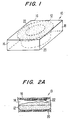
- Figure 1 illustrates a food package 10.
- Food package 10 contains a food item 12, shown as a pot pie, within food receiving space 14.
- a number of additional food items such as fruit pies and stews could also be effectively heated by a package made in accordance with the present invention.
- Food package 10 includes a top panel 16, side panels 18 and bottom panel 20 which form food receiving space 14 which is substantially transparent to microwave energy and may be constructed from a variety of microwave transparent materials.
- the food package is made from paper or paperboard, but may also be fabricated from a microwave compatible plastic material.
- Impedance matching member 22 is preferably positioned on top panel 16 over food item 12. By positioning impedance matching member 22 over food item 12, as shown in Figure 1, the microwave energy entering package 10 is impedance matched by member 22 to effectively distribute microwave energy into the center of food item 12 wherein member 22 does not interact with the microwave energy to produce heat.
- member 22 is not a heater in the conventional sense, but instead provides a novel means for effectively raising the temperature of the interior of a food item by impedance matching the incident microwave energy acting on the food.
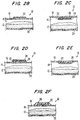
- FIG. 2A clearly shows impedance matching member 22 positioned on the interior surface of top panel 16 over food item 12.
- impedance matching member 22 is positioned from 1/8" to 5/8" above the surface of food item 12.
- Impedance matching member 22 may be printed or coated directly onto container 10 or it may be previously applied to a separate substrate.
- the substrate may be paperboard, paper, polyester film or any other microwave transparent material capable of carrying impedance matching member 22.
- Food package 10 may also be designed in a number of additional configurations, some of which are illustrated in Figures 2B-2H.
- Figure 2B shows package 10 having impedance matching member located on the outside of the package on top panel 16.
- impedance matching member 22 may also be placed between different materials.
- Figures 2C and 2D illustrate impedance matching member 22 positioned between a substrate 24 and an adhesive layer 26 used to laminate the impedance matching member to the top panel 16 of food package 10.
- Substrate 24 may be paper, paperboard, or film upon which impedance matching member 22 may be printed or coated.
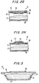
- FIGS 2E and 2F illustrate additional embodiments in which impedance matching member 22 is embedded or surrounded by a film 28 of resin or ink applied to the surface by a conventional printing process, for example. Further, impedance matching member 22 can be sandwiched by a material 30, such as paper, paperboard, or plastic, which is adhered to a surface by an adhesive layer 26, as illustrated in Figures 2G and 2H. These embodiments are but a few of the many package configurations possible which utilize impedance matching member 22.
- FIG 3 illustrates yet another possible package configuration 10 wherein impedance matching member 22 is located on a lid of a food tray, rather than on a separate carton, as shown in Figures 1 and 2A-2H.
- Impedance matching member 22 comprises a film of thinly flaked material embedded or held within a dielectric binder material.
- impedance matching member 22 is shaped to be diametrically smaller than food item 12.
- the dielectric binder may be chosen from a variety of commercially available binder materials, for example silicone or acrylic binders.
- the preferred dielectric binder is a low loss tangent, high dielectric constant, and high dielectric strength material (all measured at 2.45 GHz).
- Low loss silicone binders such as Dow CorningTM 1-2577, and some acrylics, such as the styrene/acrylic Joncryl 611 from Johnson WaxTM, may be utilized to provide coatings with the desired impedance matching response without producing detrimental heat in the presence of microwave energy.
- a resin with a high loss tangent, such a nitrocellulose is utilized as the binder material, the resultant impedance matching coating will undergo excessive heating when exposed to microwave energy resulting in a variety of undesirable side effects, such as scorching or melting of the coating substrate.
- the thinly flaked material of the present invention is essential to achieving advantageous results.
- the flakes are generally flat and planar and made from a metallic material. It is important that the flake have a length which allows it to lay substantially flat in the binder material. At the same time, the flake should be at a length which allows it to be printed onto a substrate by a conventional printing process, such as gravure printing.
- the desired flakes are aluminum metal having an average longest dimension within the range of approximately 8-75 micrometers ( ⁇ m) and a smaller dimension or width in the range of 5-35 ⁇ m. Preferably, the longest dimension is within the range of 10-30 ⁇ m. Although aluminum metal is preferred, other metal materials may be equally applicable to the present invention.
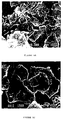
- the preferred flakes of the present invention are shown under magnification.
- the flakes themselves appear to have a substantially smooth perimeter with a limited number of fragmented flakes present in the binder.
- the apparent smoothness of a flake may depend upon the degree of magnification.
- describing the flake perimeter as smooth can be defined by comparing it to a flake having a jagged perimeter.
- the smoothness of the perimeter of the flake can be contrasted with a flake which is jagged to the extent that a jagged flake includes a multiplicity of intersecting straight lines to form angles less than 180°.
- the smooth perimeter of the flake provides a lesser total parametric length than a jagged perimeter.
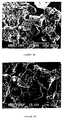
- Figures 5A-5C and 6A-6C illustrate prior art metal flakes. It is clear by comparing the flakes shown in Figures 5A-5C and 6A-6C with those shown in Figures 4A and 4B that the flakes shown in Figures 4A and 4B have a smaller parametric length.
- the thickness of the flake material is also important in obtaining the advantageous features of the present invention.
- the flake should have a sufficient thickness to maintain flake dimensional integrity and sufficient mechanical strength to endure dispersion in the binder material.
- the flake material should not be so thick that it no longer is capable of providing close packing between adjacent flakes.
- the flakes have a thickness within the range of 100-500 ⁇ . More preferably, the flake has a thickness within the range of about 100-200 ⁇ . If the flake material is made of aluminum metal, the preferred aluminum flake is made from aluminum metal by vapor deposition and the thickness should provide an optical density within the range of 1-4.
- the flake material also, preferably has an aspect ratio of at least 1000.
- Such an aspect ratio provides an impedance matching member 22 having an effective dielectric constant of at least 4,000.
- a thin impedance matching member 22 is capable of matching the impedance of the microwave energy present in a microwave oven and in so doing direct the microwave energy more effectively into the interior of the food item held within the package below the impedance matching member 22.
- Impedance matching member 22 formed in this manner is for all intents and purposes a non-conductive film with a very high dielectric constant.
- x ⁇ dZ o /2 (resistive film)
- x ⁇ if ⁇ r ⁇ o Z o d (capacitive film)
- Z o is the free-space impedance of the radiation as projected to the plane of the turn
- ⁇ is the bulk conductivity of the resistive film
- d is the film thickness
- i is the square root of negative one (imaginary)
- f is the frequency
- ⁇ o the permittivity of free space (generally, equal to 8.85x10 -12 Farads/meter)
- ⁇ r is the complex, relative dielectric constant of the capacitive film.
- x is real
- T is in phase with the incoming radiation
- R is 180° out of phase
- the absolute values of R and T sum to one.
- x is a complex number for the capacitive film
- the phase of R and T depends on the magnitude of x and the phase of ⁇ r .
- T still equals 1 + R, but the sum of the absolute values of T and R becomes greater than one.
- 1 .
- Power distribution in thin film radiation may be calculated with simple electrical networks.
- the incoming radiation is represented as source with an output impedance of free space (Z o ), the film is a resistor or capacitor to ground having a value of Z o /2x and the space behind the film is another Z o resistor to ground.
- Z d the impedance of the dielectric
- x is real so T decrease monotonically with x. If the dielectric is lossy, ⁇ r has a negative imaginary component. Therefore, as ⁇ x ⁇ initially increases for capacitive films (x imaginary), the x term starts to cancel the imaginary part of ⁇ r , and T actually increases. Eventually, x will dominate ⁇ r and T will drop, but for a while, the capacitive film improves the impedance match of lossy foods and, as a result, increases the energy input thereto.
- T is known, the portion of the energy transmitted into a dielectric food load can be calculated as the real part of ⁇ r 1 ⁇ 2 TT*, where T* is the complex conjugant of T.
- the effective load of the film and a load is the parallel combination of the film and the load transferred to the film. Therefore, the inverse of the effective load is the sum of the inverses of the film impedance and the transferred impedance of the load.
- Z impedance
- the inverse of the normalized impedance will be 1.0 plus some positive imaginary number, Ni. If a film is chosen where x equals i/N, then the inverse of x is -Ni and the total impedance is Z o which would be a perfect impedance match with no energy reflected. Since the capacitive film of the present invention does not absorb, all the energy ends up as heat in the load. For this reason, it is very effective for heating the interior portions of a high dielectric food item, such as a pot pie or fruit pie.
- x opt i[
- Avery Dennison Corporation produces aluminum flakes having aspect ratios of at least 1000 which provide the x-values required for the present invention in films of practical thickness.
- the preferred aluminum flakes useful for the present invention are produced by the Decorative Films Division of Avery Dennison Corporation and have the product designations of METALURETM L-57083, L-55350, L-56903, L-57097, L-57103 and L-57102.
- flakes are produced by vacuum vapor depositing a layer of metal on a thin soluble polymeric coating which has been applied to a smooth carrier.
- a biaxially oriented polyester type film is used as the carrier, such as MYLARTM, a product of Du Pont.
- the metal layer formed on the carrier is stripped therefrom by dissolving the soluble coating.
- the preferred vapor deposition thickness for aluminum metal gives an optical density of 1-4 before stripping. This provides a flake having the desired shape and dimensions. If the deposited metal films are too thin, the flakes will not be strong enough to prevent curling upon stripping. On the other hand, if the deposited metal film is too thick, the surface of the film tends to give a rough surface to the flake. Following stripping, the metal layer is then mechanically mixed to provide the desired flake particle size while substantially preventing fragmentation of the flake.
- the flakes generally have an average major dimension or length of 8-75 ⁇ m with very few fine flakes having a major dimension less than 5 ⁇ m.
- the width of the flake falls within the range of 5-35 ⁇ m. Fines tend to keep the surfaces of the flakes apart.
- L-57103 and L-57102 flakes are microwave responsive, these flakes are difficult to coat and are not, therefore, the most preferred flake materials for impedance matching. However, these flakes are the preferred flake materials for providing microwave shielding discussed in greater detail below.
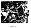
- Figures 5A-5C show a STAPA-C VIII type aluminum flake produced by Obron Corp.
- Figures 6A-6C show an ALCAN 5225 type aluminum flake material produced by Alcan. It is clear from these photographs taken at both X3,000 and X8,000 that these materials have less surface area than the Avery type flakes shown in Figures 4A-4B. This results in an aspect ratio of only 75-80 for the ALCAN 5225 flake and approximately 200 for the STAPA-C VIII flake.
- the Avery type flake has a large surface area while also being very thin to provide the Avery flake with a higher aspect ratio, and ultimately a higher dielectric constant when immersed in a binder than other aluminum flake materials.
- the Avery flake has rounded and smooth parametric edges, rather, than the rough edges shown by the conventional flake materials and includes less flake fragments.
- the aluminum flake material produced by Avery is important to the operation of the impedance matching film of the present invention primarily because of the extremely high dielectric constant provided by these flakes.
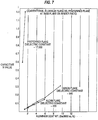
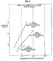
- a performance comparison of the Avery aluminum flake with aluminum flake material produced by other manufacturers clearly illustrates the significant advantages of the Avery type flake material at the same total mass of aluminum. Tests were conducted to the compare the x-values, mathematically described above, of a number of conventional flake materials with one of the Avery flake samples.
- a similar formulation was made by premixing 11g of STAPA-C VIII (aluminum flake paste at 65% solids in isopropyl alcohol having a particle size of 11 ⁇ m) with 12.5g of ethyl acetate until the flake was uniformly dispersed. To this was added 7.8g of Dow Corning 1-2577 conformal coating (5.6g of silicone resin solids in toluene), 30.3g of toluene, and 1.4 g of Hercules ethylcellulose (T-300 grade which was dissolved in 29.7g of toluene). The resulting formulation was 10% solid and had a 50/50 ratio of aluminum flake to total binder. This formulation was also applied to a polyester sheet film as described above.
- STAPA-C VIII aluminum flake paste at 65% solids in isopropyl alcohol having a particle size of 11 ⁇ m
- a similar mixture was formed using the preferred Avery flake material, L-56903.
- a 50/50 ratio of aluminum flake to total binder was formed, as described in greater detail below in Example 7.
- the results of these three sheet materials are shown in Figure 7 as a function of aluminum coat weight.
- Figure 7 clearly shows that the use of these conventional aluminum flake materials, rather than a flake material having the characteristics of the Avery flake, is impractical to achieve the impedance matching ability of the present thin film. Specifically, to reach a desired x-value of 0.7i-2.0i, or more preferably, 1.0i-1.8i, 20-40 lbs./3000 sq.ft. of conventional flake would be required. Such an extreme amount of flake material would not easily form a thin film. Further, even at this extremely high level, there is no indication that such a large amount of flake material would actually perform the impedance matching function of the present invention.
- a coating was made by mixing 5,000g of toluene with 4,000g of aluminum flake (Metalure L-56903 - 10% solids in ethyl acetate). To this was added a mixture of 556g of Dow Corning 1-2577, which is silicone resin (73 % solids in toluene) and 444g of toluene. The resulting formulation was 8 % solids with a 1:1 ratio of aluminum flake and binder solids. The viscosity of the formulation was 22 sec. with a #2 Zahn cup. This formulation was applied to a PET film (grade 813/92 from ICI) on a web fed gravure press at 113 ft./min. using a 100 line cylinder with etched quadrangular cells.
- a coating was made by mixing 3360g of aluminum flake (Metalure L-56903; 10% solids in ethyl acetate) with 1920g of n-propyl acetate. To this mixture was added 108g of Joncryl SCX-611 (an acrylic resin from S.C. Johnson & Sons, Inc.) in 252g of n-propyl acetate and 36g of ethylcellulose (grade N-300 from Hercules Inc.) in 324g of n-propyl acetate. This mixture was diluted to 6% total solids by adding an additional 2,000g of n-propyl acetate. The viscosity of the resulting mixture was 24 sec. with a #2 Zahn cup. The resulting mixture was applied to a PET film using a gravure press, as described above in Example 3, at 125 ft./min. line speed.
- Joncryl SCX-611 an acrylic resin from S.C. Johnson & Sons, Inc.
- a coating using conventional aluminum flake material was also made by first mixing 3,200g of STAPA-C VIII (a 65% solids paste in isopropyl alcohol) with 2,300g of ethyl acetate and 1,000g of isopropyl acetate until a uniform dispersion was obtained. To this dispersion was added a mixture of 1,250g of Dow Corning 1-2577 (72% solids in toluene) and 2,250g of toluene. The combined formulation was 30% solids and had a viscosity of 17 sec. with a #2 Zahn cup. The resulting mixture was applied to a PET film using a gravure press, as described above in Example 3, at 75-85 ft./min. line speed.
- STAPA-C VIII a 65% solids paste in isopropyl alcohol
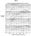
- the effect of flake size of the preferred aluminum flake material having the characteristics of the flakes produced by Avery on the x-value is also important in achieving the desired impedance matching characteristics.
- a number of coating formulations were made using each of the flakes noted above from Avery, Inc., as well as a formulation using the STAPA-C VIII flake from Obron Corp.
- the coating formulation was made by mixing 56g of aluminum flake slurry (Metalure L-55350), which is 10% solids in ethyl acetate, with 32g of n-propyl acetate. To this was added 1.8g of Joncryl SCX-611 (an acrylic resin from S.C. Johnson & Sons, Inc.) in 4.2g of n-propyl acetate and 0.6g of ethylcellulose (grade N-300 from Hercules, Inc.) in 5.4g of n-propyl acetate. This 8% solids formulation, having a 70/30 aluminum flake to binder ratio, was applied to PET film with a Bird bar applicator to obtain the coat weights shown below in Table 5.
- the flakes it is also important to utilize the proper flake to binder ratio to achieve the desired x-value.
- the following tests were conducted to show the effect of the ratio of aluminum flake material in the binder on the x-value. It is assumed that as the amount of binder in the capacitive film is increased the spacing between the flakes will likewise be increased.
- the flakes may comprise about 30-80 percent by weight of the film in order to achieve the advantageous effects of the present invention.
- the flakes are present from about 30-70 percent by weight.
- a master batch of aluminum flake coating utilizing a silicone resin as the primary binder and an ethylcellulose as a thickener and secondary binder was prepared.
- the master batch contained 4.44g of Dow Corning 1-2577 conformal coating (3.2g of silicone resin solids in toluene) and 2.8g of Hercules ethylcellulose (T-300 grade which was previously dissolved in 59.2 g of toluene). To this mixture, 14g of aluminum flake solids (L-56903 in ethyl acetate at 10% solids) was added. Thus, the ratio of aluminum flake to binder was 70/30.
- An oval shaped impedance matching member 22 was placed 5/8" above a Tyson 18oz Chicken Pot Pie.
- a control carton was used which was 8 7/8" wide, 6 1/8" deep and 1 1/2" high. The control carton did not include the impedance matching member.
- a modified carton 10, similar to the carton illustrated in Figure 1, was 1 7/8" high.
- Each of the runs involved heating the pot pie for 5 minutes, rotating the pot pie 90° and then heating the pot pie for another 5 minutes.
- a test (#8) was also run using a conventional piece of aluminum foil in the same oval configuration provided above with respect to impedance matching member 22 used above in Examples 8 and 9.
- the aluminum foil oval was elevated 3/8" above a Tyson 18oz Pot Pie.
- the distance the impedance matching member 22 having the 3" x 3 1/2" oval dimensions was also adjusted to determine center pie heating (#11). Particularly, the member was placed on the inside top surface of the carton 1/2" over the surface of the pie.
- the results of Examples 10-13 are provided below in Table 9. Temperature (°F) Position #8 #9 #10 #11 C 64 123 120 155 LI 190 195 198 192 IC 192 185 197 188 RI 192 182 192 180 LC 193 197 198 180 RC 184 182 191 180 LO 187 186 193 187 OC 188 194 195 185 RO 182 184 192 185
- Cartons were also tested to determine an optimum size for a rectangular or square impedance matching member which elevates the temperature of a pot pie similar to the advantageous heating provided by the oval design.
- a series of tests were run on a Tyson 18oz Chicken Pot Pie using a carton similar to the carton used above in Examples 14-17 having a carton depth of 1 5/8", but replacing the oval impedance matching member with a rectangular member 2 1/2" x 2".
- Table 11 provides the results of three different tests run with the rectangular member (#17, #18, #19, #20).
- a control test was also run without a carton (#21).
- the impedance matching member of the present invention may also be useful for altering the relative cooking rates and temperatures of two different items. Such a result may be very effective in complete microwave dinners that include a variety of different foods, each requiring different heating characteristics. For example, the meat portion of a complete dinner may require higher heating temperatures than the vegetable portion. However, to provide the consumer with added convenience, these items are commonly provided in the same packaging tray. The use of the impedance matching member of the present invention for one portion of the tray and not another can cause dramatic differences in temperature.
- the impedance matched sections of the oven contents heated faster than unmatched sections. However, impedance matching the total contents did not increase the total oven output. Partial impedance matching generally redistributes the heating in the oven.
- the impedance matching member of the present invention may also be configured in a nonuniform nature to function in a microwave oven similar to a convex glass lens.
- Figure 11 illustrates an example of a modified impedance matching member 22' within package 10 which is configured similar to a convex optical lens. Such a configuration is useful to further direct microwave radiation to desired areas of package 10.
- the film can also act as a shield.
- the film may function as a shield to reduce the amount of microwave energy reaching a food item placed below the film.
- the ratio of the electric field amplitude entering a dielectric food stuff with a capacitive film shield at the surface to the field entering without such a shield can be represented as: 1 + ⁇ 1 ⁇ 2 1 + 2x + ⁇ 1 ⁇ 2 where ⁇ is the effective dielectric constant.
- the level of capacitive film depends on the dielectric constant.
- the capacitive x-value should be at least 10i.
- Table 5 provides an example of a flake material and coat weight capable of providing shielding. Specifically, the L-57103 flake, having an average length of 25 ⁇ m and a coat weight of 1.0-1.7 lbs/3000 sq.ft.
- Tests were conducted to demonstrate the usefulness of a high x value capacitive film for shielding foods in a microwave oven. Specifically, two paper cups containing 120g of water were each placed in a 700 watt Litton microwave oven. First, each cup of water having no flaked material introduced in the cup was heated in a 700 watt LITTONTM microwave oven until one reached about 200°F. The temperature in each cup was monitored by two Luxtron probes suspended at fixed, reproducible positions in the water. The average heat dissipation in watts was calculated for each cup of water from the average temperature rise and heating time. Next, aluminum foil patches were glued on the bottom and the sides of one of the cups designated at cup B. Again, the average power dissipation was calculated.
- the 1.5i film had little influence on the power dissipation when placed at the surface of the container.
- the aluminum foil provides significant shielding illustrated by the reduction of power dissipation in cup B in Test 2.
- Test 4 illustrates that a 20i film also provides shielding and also demonstrates that, by using capacitive films made in accordance with the present invention, the amount of shielding can be controlled by adjusting the x-value of the film.
Landscapes
- Engineering & Computer Science (AREA)
- Life Sciences & Earth Sciences (AREA)
- Food Science & Technology (AREA)
- Mechanical Engineering (AREA)
- Cookers (AREA)
- Package Specialized In Special Use (AREA)
- Constitution Of High-Frequency Heating (AREA)
- Food Preservation Except Freezing, Refrigeration, And Drying (AREA)
- General Preparation And Processing Of Foods (AREA)
Claims (14)
- Emballage (10) pour stocker et chauffer des aliments par micro-ondes, dans lequel l'emballage (10) est au moins en partie essentiellement transparent à de l'énergie du type à hyperfréquences et forme une cavité de réception pour les aliments, englobant un panneau inférieur (16), un panneau supérieur (20) et des panneaux latéraux (18) joignant le panneau inférieur (16) au panneau supérieur (20), dans lequel l'emballage est muni, au moins en partie, de flocons enrobés dans un liant diélectrique,
caractérisé
en ce qu'on prévoit un moyen d'adaptation de l'impédance comprenant un film capacitif contigu constitué par les flocons enrobés dans un liant diélectrique, sur la surface d'au moins un des panneaux (16, 18, 20) pour adapter l'impédance de l'énergie du type à hyperfréquences pénétrant dans l'emballage (10) sans agir réciproquement avec l'énergie du type à hyperfréquences pour produire de la chaleur. - Emballage (10) selon la revendication 1, caractérisé en ce que les flocons sont de forme généralement plane et en ce que les flocons sont constitués d'une matière métallique, de préférence d'aluminium.
- Emballage (10) selon la revendication 1 ou 2, caractérisé en ce que les flocons possèdent une longueur maximale moyenne dans le domaine d'environ 8-75 µm et une épaisseur dans le domaine d'environ 1 x 10⁻⁸ à 5 x 10⁻⁸ m, de préférence dans le domaine d'environ 1 x 10⁻⁸ à 2 x 10⁻⁸ m, et/ou en ce que les flocons possèdent un rapport nominal d'aspect d'au moins environ 1.000.
- Emballage (10) selon l'une quelconque des revendications précédentes, caractérisé en ce que les flocons sont présents à un poids superficiel dans le domaine d'environ 0,48-4,24 g/m2 (0,3-2,6 livres/3.000 pieds carrés), de préférence à un poids superficiel dans le domaine d'environ 0,48-2,93 g/m2 (0,3-1,8 livre/3.000 pieds carrés).
- Emballage (10) selon l'une quelconque des revendications précédentes, caractérisé en ce que les flocons comprennent d'environ 30 à 70 pour cent en poids du film, de préférence 70 pour cent en poids du film.
- Emballage (10) selon l'une quelconque des revendications précédentes, caractérisé en ce que le moyen d'adaptation de l'impédance possède une constante diélectrique effective d'au moins 4.000.
- Emballage (10) selon l'une quelconque des revendications précédentes, caractérisé en ce que le moyen d'adaptation de l'impédance est positionné sur le panneau supérieur (20), au-dessus des aliments, de préférence à une distance d'environ 0,32 cm (1/8") à 1,6 cm (5/8").
- Emballage (10) selon l'une quelconque des revendications précédentes, caractérisé en ce que le moyen d'adaptation de l'impédance possède un diamètre inférieur à celui des aliments maintenus dans l'emballage (10), de préférence dans lequel le moyen d'adaptation de l'impédance est de forme ovale.
- Emballage (10) selon l'une quelconque des revendications précédentes, caractérisé en ce que la surface d'au moins un des panneaux (16, 18, 20) comprend du papier ou du carton ou en ce que le substrat du film représente du papier, du carton ou un film en matière plastique.
- Emballage (10) selon l'une quelconque des revendications précédentes, caractérisé en ce que le moyen d'adaptation de l'impédance est dimensionné et espacé par rapport aux aliments de telle sorte que le moyen d'adaptation de l'impédance élève la température des aliments en augmentant la quantité d'énergie du type à hyperfréquences orientée sur les aliments dans au moins une zone prédéterminée de ces derniers en fonction de la dimension et de l'écartement du film sans agir réciproquement avec l'énergie du type à hyperfréquences pour produire de la chaleur.
- Emballage (10) selon l'une quelconque des revendications précédentes, caractérisé en ce que le film possède une valeur capacitive (x) dans le domaine d'environ 0,7i à 2,0i.
- Emballage (10) selon l'une quelconque des revendications précédentes, caractérisé en ce que le moyen d'adaptation de l'impédance est prévu sur une surface étendue d'au moins un panneau (16, 18, 20) pour soumettre à une adaptation de l'impédance l'énergie du type à hyperfréquences pénétrant dans l'emballage (10), dans lequel le moyen d'adaptation de l'impédance est de forme convexe de telle sorte que son épaisseur au centre est supérieure à l'épaisseur à sa périphérie pour focaliser l'énergie du type à hyperfréquences dont l'impédance a été adaptée, en direction des aliments, dans le but d'élever la température des aliments en augmentant la quantité d'énergie du type à hyperfréquences orientée vers les aliments dans une zone correspondant à la dimension du moyen d'adaptation de l'impédance et de l'écartement du moyen d'adaptation de l'impédance par rapport aux aliments sans agir réciproquement avec l'énergie du type à hyperfréquences pour produire de la chaleur.
- Emballage (10) selon l'une quelconque des revendications 1 à 9, caractérisé en ce qu'on prévoit un moyen d'adaptation de l'impédance positionné à proximité d'une denrée alimentaire (12) pour protéger cette dernière contre l'énergie du type à hyperfréquences, dans lequel le film capacitif est une matière composite sous la forme d'un film contigu de flocons généralement planes enrobés dans un liant diélectrique en une quantité suffisante pour réduire l'énergie du type à hyperfréquences atteignant la denrée alimentaire (12) lorsque ladite matière composite est positionnée à sa proximité, dans lequel, de préférence, la valeur de x du film capacitif de la matière composite est supérieure à 10i et/ou dans lequel la constante diélectrique effective de la matière composite s'élève à au moins environ 100.000.
- Emballage (10) selon l'une quelconque des revendications précédentes, caractérisé en ce qu'on prépare ledit film constitué par des flocons en passant par les étapes consistant à:a) déposer, à partir de sa phase vapeur, une couche de métal d'aluminium, de préférence possédant une densité optique dans le domaine d'environ 1 à 4, sur un revêtement polymère soluble appliqué sur un support; etb) pelliculer la couche du support.
Applications Claiming Priority (2)
| Application Number | Priority Date | Filing Date | Title |
|---|---|---|---|
| US08/141,724 US5424517A (en) | 1993-10-27 | 1993-10-27 | Microwave impedance matching film for microwave cooking |
| US141724 | 1993-10-27 |
Publications (3)
| Publication Number | Publication Date |
|---|---|
| EP0650905A2 EP0650905A2 (fr) | 1995-05-03 |
| EP0650905A3 EP0650905A3 (fr) | 1995-08-23 |
| EP0650905B1 true EP0650905B1 (fr) | 1998-09-23 |
Family
ID=22496945
Family Applications (1)
| Application Number | Title | Priority Date | Filing Date |
|---|---|---|---|
| EP94116521A Expired - Lifetime EP0650905B1 (fr) | 1993-10-27 | 1994-10-20 | Emballage pour four à micro-ondes avec fonction pour régler l'adaptation de l'impédance |
Country Status (6)
| Country | Link |
|---|---|
| US (1) | US5424517A (fr) |
| EP (1) | EP0650905B1 (fr) |
| JP (2) | JP3946783B2 (fr) |
| AT (1) | ATE171439T1 (fr) |
| CA (1) | CA2131434C (fr) |
| DE (1) | DE69413492T2 (fr) |
Families Citing this family (138)
| Publication number | Priority date | Publication date | Assignee | Title |
|---|---|---|---|---|
| US5781110A (en) * | 1996-05-01 | 1998-07-14 | James River Paper Company, Inc. | Electronic article surveillance tag product and method of manufacturing same |
| US6005234A (en) * | 1998-07-30 | 1999-12-21 | Weaver Popcorn Company | Microwave popcorn bag with cross mitre arrangement |
| US6137098A (en) * | 1998-09-28 | 2000-10-24 | Weaver Popcorn Company, Inc. | Microwave popcorn bag with continuous susceptor arrangement |
| FR2818086B1 (fr) * | 2000-12-11 | 2003-06-20 | Centre Nat Rech Scient | Traitement par micro-ondes d'objets et de pieces unitaires |
| EP2181939B1 (fr) * | 2002-02-08 | 2015-05-20 | Graphic Packaging International, Inc. | Matériel pour emballage interactif aux micro-ondes |
| US7323669B2 (en) | 2002-02-08 | 2008-01-29 | Graphic Packaging International, Inc. | Microwave interactive flexible packaging |
| ATE543550T1 (de) | 2002-03-15 | 2012-02-15 | Graphic Packaging Int Inc | Behälter mit einem spritzgegossenen merkmal |
| US20060081625A1 (en) * | 2002-10-11 | 2006-04-20 | The Vivian A. Skaife Trust | Food packaging for microwave pressure cooking and method of using same |
| US6960748B2 (en) * | 2003-10-09 | 2005-11-01 | Smurfit-Stone Container Enterprises, Inc. | Collapsible microwave popcorn box |
| AU2005212418A1 (en) * | 2004-02-09 | 2005-08-25 | Graphic Packaging International, Inc. | Microwave cooking package |
| ATE547348T1 (de) | 2004-08-25 | 2012-03-15 | Graphic Packaging Int Inc | Absorbierende mikrowellen-interaktive verpackung |
| US7982168B2 (en) * | 2004-08-25 | 2011-07-19 | Graphic Packaging International, Inc. | Absorbent microwave interactive packaging |
| US20060096978A1 (en) * | 2004-11-10 | 2006-05-11 | Graphic Packaging International, Inc | Insulated packages for microwaveable foods |
| US7514659B2 (en) * | 2005-01-14 | 2009-04-07 | Graphic Packaging International, Inc. | Package for browning and crisping dough-based foods in a microwave oven |
| ATE497918T1 (de) | 2005-04-11 | 2011-02-15 | Graphic Packaging Int Inc | In der mirkowelle erwärmbare, leicht zu öffnende lebensmittelverpackung |
| EP1888431A2 (fr) * | 2005-04-14 | 2008-02-20 | Graphic Packaging International, Inc. | Materiaux thermo-activables reagissant aux micro-ondes |
| US20080274354A1 (en) * | 2005-04-26 | 2008-11-06 | Rettker James P | Embossed Metallic Flakes Process and Product |
| JP4856176B2 (ja) | 2005-05-25 | 2012-01-18 | グラフィック パッケージング インターナショナル インコーポレイテッド | マルチコンポーネント・ミールのためのマイクロ波包装 |
| US20110204046A1 (en) * | 2005-05-25 | 2011-08-25 | Middleton Scott W | Microwave Heating Construct for Frozen Liquids and Other Items |
| ES2751955T3 (es) | 2005-06-17 | 2020-04-02 | Graphic Packaging Int Llc | Susceptores que pueden equilibrar tensión y efectividad |
| US20070184977A1 (en) * | 2005-07-29 | 2007-08-09 | Spiller Robert W | Microwavable construct with thermally responsive indicator |
| US7361872B2 (en) | 2005-08-16 | 2008-04-22 | Graphic Packaging International, Inc. | Variable serving size insulated packaging |
| US8217325B2 (en) * | 2005-09-12 | 2012-07-10 | Graphic Packaging International, Inc. | Elevated microwave heating construct |
| US7345262B2 (en) * | 2005-11-07 | 2008-03-18 | Graphic Packaging International, Inc. | Microwave interactive display package |
| US7667167B2 (en) | 2005-12-08 | 2010-02-23 | Graphic Packaging International, Inc. | Microwave food heating package with removable portion |
| US20070221666A1 (en) * | 2006-03-09 | 2007-09-27 | Keefe Daniel J | Susceptor with apertured support |
| JP4995892B2 (ja) * | 2006-03-10 | 2012-08-08 | グラフィック パッケージング インターナショナル インコーポレイテッド | 射出成形複合構成物 |
| CA2644685A1 (fr) | 2006-03-10 | 2007-09-20 | Graphic Packaging International, Inc. | Contenant a bande hyperfrequence interactive |
| EP2077240B1 (fr) * | 2006-03-31 | 2010-11-17 | Graphic Packaging International, Inc. | Recipient, pour chauffer, rendre croustillant et pour brunir des aliments dans un four à micro-ondes |
| CA2645061C (fr) * | 2006-03-31 | 2012-10-23 | Graphic Packaging International, Inc. | Construction de support d'aliments |
| US8853601B2 (en) | 2006-03-31 | 2014-10-07 | Graphic Packaging International, Inc. | Microwavable construct for heating, browning, and crisping rounded food items |
| WO2007127371A2 (fr) * | 2006-04-27 | 2007-11-08 | Graphic Packaging International, Inc. | Suscepteur à fusible multidirectionnel |
| US8063344B2 (en) * | 2006-04-27 | 2011-11-22 | Graphic Packaging International, Inc. | Microwave energy interactive food package |
| US9205968B2 (en) | 2006-04-27 | 2015-12-08 | Graphic Packaging International, Inc. | Multidirectional fuse susceptor |
| BRPI0711290B1 (pt) | 2006-05-12 | 2019-11-19 | Graphic Packaging Int Llc | folha para aquecimento interativo para energia de microondas, e método para usar a folha para aquecimento interativo para energia de microondas |
| US8680448B2 (en) * | 2006-05-15 | 2014-03-25 | Graphic Packaging International, Inc. | Microwavable construct with contoured heating surface |
| US8803050B2 (en) * | 2006-05-15 | 2014-08-12 | Graphic Packaging International, Inc. | Microwavable construct with contoured heating surface |
| JP4886031B2 (ja) * | 2006-05-19 | 2012-02-29 | グラフィック パッケージング インターナショナル インコーポレイテッド | 調理用パッケージ |
| US8826959B2 (en) | 2006-06-29 | 2014-09-09 | Graphic Packaging International, Inc. | Heat sealing systems and methods, and related articles and materials |
| US8753012B2 (en) | 2006-06-29 | 2014-06-17 | Graphic Flexible Packaging, Llc | High strength packages and packaging materials |
| CA2653547C (fr) | 2006-06-30 | 2013-04-23 | Graphic Packaging International, Inc. | Emballage chauffant par micro-onde avec revetement thermodurci |
| US8198571B2 (en) * | 2006-07-05 | 2012-06-12 | Graphic Packaging International, Inc. | Multi-compartment microwave heating package |
| EP2772452B1 (fr) | 2006-07-27 | 2016-01-06 | Graphic Packaging International, Inc. | Construction de chauffage à micro-ondes |
| EP1886936A1 (fr) * | 2006-08-11 | 2008-02-13 | Graphic Packaging International, Inc. | Conteneur pour chauffer un aliment de forme arrondie dans un four à micro-ondes et son ébauche |
| EP1886926A1 (fr) * | 2006-08-11 | 2008-02-13 | Graphic Packaging International, Inc. | Structure pour le chauffage aux micro-ondes de plusieurs produits alimentaires |
| ES2625132T3 (es) * | 2006-10-16 | 2017-07-18 | Graphic Packaging International, Inc. | Producto fabricado elevado de calentamiento por microondas |
| WO2008049048A2 (fr) | 2006-10-18 | 2008-04-24 | Graphic Packaging International, Inc. | Outil pour former un article ou un récipient en trois dimensions |
| EP2079639B1 (fr) | 2006-10-26 | 2010-08-25 | Graphic Packaging International, Inc. | Plateau de chauffage aux micro-ondes élevé |
| EP2453177B1 (fr) | 2007-01-22 | 2013-08-28 | Graphic Packaging International, Inc. | Récipient à micro-ondes pour chauffage de four |
| US9073689B2 (en) * | 2007-02-15 | 2015-07-07 | Graphic Packaging International, Inc. | Microwave energy interactive insulating structure |
| US20080230537A1 (en) * | 2007-03-23 | 2008-09-25 | Lafferty Terrence P | Susceptor with corrugated base |
| US8629380B2 (en) * | 2007-03-23 | 2014-01-14 | Graphic Packaging International, Inc. | Susceptor with corrugated base |
| EP2139787A4 (fr) * | 2007-05-01 | 2011-05-25 | Graphic Packaging Int Inc | Emballage pour réchauffer un produit alimentaire |
| CA2684507A1 (fr) * | 2007-05-01 | 2008-11-13 | Graphic Packaging International, Inc. | Emballage pour rechauffer un produit alimentaire |
| WO2008157750A2 (fr) * | 2007-06-21 | 2008-12-24 | Graphic Packaging International, Inc. | Emballage pour contenir et distribuer un article alimentaire |
| EP2176139B1 (fr) * | 2007-08-13 | 2016-03-23 | Graphic Packaging International, Inc. | Flan pour la formation d'une structure de chauffage par micro-ondes |
| CA2700871C (fr) * | 2007-10-03 | 2012-12-04 | Graphic Packaging International, Inc. | Manchon de chauffage aux micro-ondes |
| CA2707054C (fr) | 2007-12-28 | 2013-02-26 | Graphic Packaging International, Inc. | Construction composite moulee par injection, et outil pour la formation de cette construction |
| WO2009088904A2 (fr) * | 2007-12-31 | 2009-07-16 | Graphic Packaging International, Inc. | Outil pour former une construction |
| CA2715627C (fr) * | 2008-02-18 | 2015-02-03 | Graphic Packaging International, Inc. | Appareil pour preparer un article alimentaire dans un four a micro-ondes |
| EP2245375A4 (fr) * | 2008-02-18 | 2013-05-08 | Graphic Packaging Int Inc | Appareil pour cuire des articles alimentaires bruts dans un four à micro-ondes |
| EP2250859B1 (fr) | 2008-03-14 | 2019-08-28 | Graphic Packaging International, LLC | Suscepteur avec base ondulée |
| JP5618980B2 (ja) * | 2008-03-27 | 2014-11-05 | グラフィックパッケージング インターナショナル インコーポレイテッド | 自己蒸気抜きマイクロ波加熱用パッケージ及び該パッケージを用いる方法 |
| US8247750B2 (en) * | 2008-03-27 | 2012-08-21 | Graphic Packaging International, Inc. | Construct for cooking raw dough product in a microwave oven |
| US7975871B2 (en) | 2008-04-04 | 2011-07-12 | Graphic Packaging International, Inc. | Container with injection-molded feature and tool for forming container |
| EP2272303A2 (fr) * | 2008-05-09 | 2011-01-12 | Graphic Packaging International, Inc. | Plateau et enveloppe interactifs à énergie micro-ondes |
| JP5265765B2 (ja) * | 2008-06-09 | 2013-08-14 | グラフィック パッケージング インターナショナル インコーポレイテッド | 微小孔を有するマイクロ波エネルギー相互作用構造体 |
| EP2296999B1 (fr) | 2008-07-11 | 2014-03-05 | Graphic Packaging International, Inc. | Contenant pour chauffage par micro-ondes |
| US20100006567A1 (en) * | 2008-07-14 | 2010-01-14 | Cole Lorin R | Cooking package |
| EP2493263B1 (fr) | 2008-07-31 | 2014-06-25 | Graphic Packaging International, Inc. | Construction de chauffage à micro-ondes |
| CA2729975C (fr) * | 2008-08-14 | 2014-11-18 | Graphic Packaging International, Inc. | Construction de chauffage aux micro-ondes ayant un fonds pouvant etre eleve |
| US20110024413A1 (en) * | 2008-09-17 | 2011-02-03 | Cole Lorin R | Construct for Browning and Crisping a Food Item in a Microwave Oven |
| EP2365929A4 (fr) * | 2008-09-17 | 2014-03-19 | Graphic Packaging Int Inc | Dispositif pour faire dorer et donner du croustillant à un aliment dans un four à micro-ondes |
| WO2010056696A2 (fr) | 2008-11-12 | 2010-05-20 | Graphic Packaging International, Inc. | Structure de suscepteur |
| US8815317B2 (en) | 2009-01-12 | 2014-08-26 | Graphic Packaging International, Inc. | Elevated microwave heating construct |
| US8497455B2 (en) * | 2009-03-11 | 2013-07-30 | Bemis Company, Inc. | Microwave cooking containers with shielding |
| WO2010129205A2 (fr) * | 2009-04-28 | 2010-11-11 | Graphic Packaging International, Inc. | Structure de suscepteur ventilé |
| WO2010127214A2 (fr) * | 2009-05-01 | 2010-11-04 | Graphic Packaging International, Inc. | Construction avec élément de positionnement |
| CA2761154C (fr) | 2009-06-17 | 2014-02-18 | Graphic Packaging International, Inc. | Outil pour la formation d'un contenant ou d'une construction a trois dimensions |
| JP5814239B2 (ja) * | 2009-08-26 | 2015-11-17 | グラフィック パッケージング インターナショナル インコーポレイテッド | デネスティング構成を有する、容器ブランク及び容器 |
| US8464871B2 (en) | 2009-09-14 | 2013-06-18 | Graphic Packaging International, Inc. | Blank and forming tool for forming a container |
| US8727204B2 (en) * | 2009-11-16 | 2014-05-20 | Graphic Packaging International, Inc. | Expandable carton |
| EP2510285B1 (fr) | 2009-12-09 | 2016-01-27 | Graphic Packaging International, Inc. | Construction de chauffage de plat profond par micro-ondes |
| US8445043B2 (en) | 2009-12-30 | 2013-05-21 | H.J. Heinz Company | Multi-temperature and multi-texture frozen food microwave heating tray |
| WO2011082205A2 (fr) * | 2009-12-30 | 2011-07-07 | Graphic Packaging International, Inc. | Appareil et procédé de positionnement et d'actionnement sur un récipient |
| US20110180594A1 (en) * | 2010-01-25 | 2011-07-28 | Fitzwater Kelly R | Package for Multiple Food Items |
| WO2011126751A2 (fr) * | 2010-03-29 | 2011-10-13 | Graphic Packaging International, Inc. | Appareil de chauffage à micro-ondes comprenant un berceau supportant les aliments |
| WO2012170600A2 (fr) | 2011-06-08 | 2012-12-13 | Graphic Packaging International, Inc. | Plateau à surface inférieure incurvée |
| EP2739464B1 (fr) | 2011-08-03 | 2017-11-29 | Graphic Packaging International, Inc. | Systèmes et procédés de formation de stratifiés avec un matériau interactif à énergie micro-onde gravé |
| ES2647635T3 (es) | 2012-10-17 | 2017-12-22 | Graphic Packaging International, Inc. | Recipiente con líneas de incisiones |
| ES2661103T3 (es) | 2013-03-15 | 2018-03-27 | Graphic Packaging International, Inc. | Recipiente provisto de elementos calefactores |
| MX381051B (es) | 2013-07-25 | 2025-03-12 | Graphic Packaging Int Llc | Caja de cartón para producto alimenticio. |
| EP3049338B1 (fr) | 2013-09-25 | 2018-12-26 | Graphic Packaging International, LLC | Emballage renforcé |
| US9771176B2 (en) | 2013-09-25 | 2017-09-26 | Graphic Packaging International, Inc. | Reinforced package |
| US9957080B2 (en) | 2013-09-25 | 2018-05-01 | Graphic Packaging International, Llc | Reinforced package |
| JP6290385B2 (ja) | 2013-09-26 | 2018-03-07 | グラフィック パッケージング インターナショナル インコーポレイテッドGraphic Packaging International,Inc. | 積層体並びに積層を行うシステム及び方法 |
| US9656776B2 (en) | 2013-12-16 | 2017-05-23 | Graphic Packaging International, Inc. | Construct with stiffening features |
| WO2016019218A1 (fr) | 2014-08-01 | 2016-02-04 | Graphic Packaging International, Inc. | Emballage pour micro-ondes |
| MX384607B (es) | 2014-10-21 | 2025-03-11 | Graphic Packaging Int Llc | Embalaje para un producto. |
| US10232973B2 (en) | 2014-11-07 | 2019-03-19 | Graphic Packaging International, Llc | Tray for holding a food product |
| WO2016073676A1 (fr) | 2014-11-07 | 2016-05-12 | Graphic Packaging International, Inc. | Barquette pour produit alimentaire |
| MX384916B (es) | 2014-12-22 | 2025-03-14 | Graphic Packaging Int Llc | Sistemas y métodos para formar laminados. |
| ES2774023T3 (es) | 2015-02-27 | 2020-07-16 | Graphic Packaging Int Llc | Recipiente con recubrimiento |
| AU2016255501B2 (en) | 2015-04-29 | 2019-01-03 | Graphic Packaging International, Llc | Method and system for forming packages |
| US10562675B2 (en) | 2015-04-29 | 2020-02-18 | Graphic Packaging International, Llc | Method and system for forming packages |
| US11059255B2 (en) | 2015-07-14 | 2021-07-13 | Graphic Packaging International, Llc | Method and system for forming packages |
| ES2817753T3 (es) | 2015-08-11 | 2021-04-08 | Graphic Packaging Int Llc | Paquete de calentamiento por microondas con pantalla polarizada |
| CN108290657B (zh) | 2015-08-21 | 2020-12-29 | 印刷包装国际有限责任公司 | 增强的包装件 |
| WO2017117495A1 (fr) | 2015-12-30 | 2017-07-06 | Graphic Packaging International, Inc. | Suscepteur sur film renforcé par des fibres pour une fonctionnalité étendue |
| US10604325B2 (en) | 2016-06-03 | 2020-03-31 | Graphic Packaging International, Llc | Microwave packaging material |
| EP3665002A4 (fr) | 2017-08-09 | 2021-05-05 | Graphic Packaging International, LLC | Procédé et système de formation d'emballages |
| CA3067623C (fr) | 2017-09-06 | 2022-05-10 | Graphic Packaging International, Llc | Carton comprenant au moins un support |
| USD842095S1 (en) | 2017-10-10 | 2019-03-05 | Graphic Packaging International, Llc | Carton |
| CA3104186C (fr) | 2018-07-09 | 2023-10-03 | Graphic Packaging International, Llc | Procede et systeme de formation d'emballages |
| MX2021001444A (es) | 2018-08-06 | 2021-03-09 | Graphic Packaging Int Llc | Recipiente con al menos un comportamiento. |
| MX2021005648A (es) | 2018-11-20 | 2021-07-07 | Graphic Packaging Int Llc | Charola ajustable. |
| WO2020159818A1 (fr) | 2019-01-28 | 2020-08-06 | Graphic Packaging International, Llc | Emballage renforcé |
| WO2020176284A1 (fr) | 2019-02-28 | 2020-09-03 | Graphic Packaging International, Llc | Contenant en carton pour un produit alimentaire |
| USD899246S1 (en) | 2019-04-24 | 2020-10-20 | Graphic Packaging International, Llc | Carton |
| CN110537850A (zh) * | 2019-09-05 | 2019-12-06 | 珠海格力电器股份有限公司 | 加热设备的散热控制方法、装置、烤箱及其散热控制系统 |
| USD1042113S1 (en) | 2020-01-24 | 2024-09-17 | Graphic Packaging International, Llc | Reinforcing carton |
| US12540023B2 (en) | 2020-07-15 | 2026-02-03 | Graphic Packaging International, Llc | Blanks, constructs, and associated methods for induction heating of food products |
| USD999055S1 (en) | 2020-10-29 | 2023-09-19 | Graphic Packaging International, Llc | Carton |
| AU2021376196B2 (en) | 2020-11-06 | 2025-01-30 | Graphic Packaging International, Llc | Tray for food products |
| WO2022140320A1 (fr) | 2020-12-22 | 2022-06-30 | Graphic Packaging International, Llc | Ensemble de mise en prise de fermetures-rabats pour monter des cartons et systèmes et procédés associés |
| USD1042122S1 (en) | 2021-05-27 | 2024-09-17 | Graphic Packaging International, Llc | Tray |
| USD1042118S1 (en) | 2021-05-27 | 2024-09-17 | Graphic Packaging International, Llc | Tray |
| USD1042121S1 (en) | 2021-05-27 | 2024-09-17 | Graphic Packaging International, Llc | Tray |
| USD1042116S1 (en) | 2021-05-27 | 2024-09-17 | Graphic Packaging International, Llc | Carton |
| USD1044494S1 (en) | 2021-05-27 | 2024-10-01 | Graphic Packaging International, Llc | Tray |
| USD1042117S1 (en) | 2021-05-27 | 2024-09-17 | Graphic Packaging International, Llc | Tray |
| USD1042120S1 (en) | 2021-05-27 | 2024-09-17 | Graphic Packaging International, Llc | Tray |
| USD1062459S1 (en) | 2021-05-27 | 2025-02-18 | Graphic Packaging International, Llc | Tray |
| USD1042119S1 (en) | 2021-05-27 | 2024-09-17 | Graphic Pachaging International, LLC | Tray |
| JP2024529682A (ja) | 2021-08-11 | 2024-08-08 | グラフィック パッケージング インターナショナル エルエルシー | 食品用カートン |
| WO2023107656A1 (fr) | 2021-12-10 | 2023-06-15 | Graphic Packaging International, Llc | Matériau d'emballage |
| USD1029629S1 (en) | 2022-05-31 | 2024-06-04 | Graphic Packaging International, Llc | Carton |
| USD1091334S1 (en) | 2023-05-11 | 2025-09-02 | Graphic Packaging International, Llc | Tray with divider features |
Family Cites Families (21)
| Publication number | Priority date | Publication date | Assignee | Title |
|---|---|---|---|---|
| US2820127A (en) * | 1953-03-30 | 1958-01-14 | Raytheon Mfg Co | Microwave cookers |
| US3219460A (en) * | 1962-11-20 | 1965-11-23 | Lever Brothers Ltd | Frozen food package and method for producing same |
| US3302632A (en) * | 1963-12-06 | 1967-02-07 | Wells Mfg Company | Microwave cooking utensil |
| US4641005A (en) * | 1979-03-16 | 1987-02-03 | James River Corporation | Food receptacle for microwave cooking |
| US4266108A (en) * | 1979-03-28 | 1981-05-05 | The Pillsbury Company | Microwave heating device and method |
| US4656325A (en) * | 1984-02-15 | 1987-04-07 | Keefer Richard M | Microwave heating package and method |
| NZ210921A (en) * | 1984-02-15 | 1988-07-28 | Alcan Int Ltd | Package of foodstuff for microwave oven |
| CA1239999A (fr) * | 1985-06-25 | 1988-08-02 | Richard M. Keefer | Contenant pour la cuisson d'aliments aux micro-ondes, et sa fabrication |
| US4640280A (en) * | 1985-08-12 | 1987-02-03 | Rca Corporation | Microwave hyperthermia with dielectric lens focusing |
| CA1274126A (fr) * | 1986-02-21 | 1990-09-18 | Hua-Feng Huang | Materiau composite a compose interactif absorbeur de micro-ondes |
| US4888459A (en) * | 1986-12-18 | 1989-12-19 | Alcan International Limited | Microwave container with dielectric structure of varying properties and method of using same |
| DK231487A (da) * | 1986-05-09 | 1987-11-10 | Alcan Int Ltd | Mikroboelgeovnbeholder |
| US4814568A (en) * | 1987-05-15 | 1989-03-21 | Alcan International Limited | Container for microwave heating including means for modifying microwave heating distribution, and method of using same |
| US4927991A (en) * | 1987-11-10 | 1990-05-22 | The Pillsbury Company | Susceptor in combination with grid for microwave oven package |
| US4876423A (en) * | 1988-05-16 | 1989-10-24 | Dennison Manufacturing Company | Localized microwave radiation heating |
| US4959516A (en) * | 1988-05-16 | 1990-09-25 | Dennison Manufacturing Company | Susceptor coating for localized microwave radiation heating |
| CA1339540C (fr) * | 1989-02-09 | 1997-11-11 | Richard M. Keefer | Methodes de cuisson au four a micro-ondes de produits alimentaires et autres, et dispositifs connexes |
| US5126518A (en) * | 1989-11-28 | 1992-06-30 | Beckett Industries Inc. | Microwave cooking container cover |
| US4972058A (en) * | 1989-12-07 | 1990-11-20 | E. I. Du Pont De Nemours And Company | Surface heating food wrap with variable microwave transmission |
| US5254820A (en) * | 1990-11-19 | 1993-10-19 | The Pillsbury Company | Artificial dielectric tuning device for microwave ovens |
| US5126520A (en) * | 1991-03-25 | 1992-06-30 | G & S Metal Products Company, Inc. | Shielded cover for a microwave container |
-
1993
- 1993-10-27 US US08/141,724 patent/US5424517A/en not_active Expired - Lifetime
-
1994
- 1994-09-02 CA CA002131434A patent/CA2131434C/fr not_active Expired - Fee Related
- 1994-10-20 EP EP94116521A patent/EP0650905B1/fr not_active Expired - Lifetime
- 1994-10-20 AT AT94116521T patent/ATE171439T1/de not_active IP Right Cessation
- 1994-10-20 DE DE69413492T patent/DE69413492T2/de not_active Expired - Lifetime
- 1994-10-25 JP JP28408994A patent/JP3946783B2/ja not_active Expired - Fee Related
-
2004
- 2004-09-30 JP JP2004286000A patent/JP2005047625A/ja active Pending
Also Published As
| Publication number | Publication date |
|---|---|
| CA2131434C (fr) | 1997-09-09 |
| JP3946783B2 (ja) | 2007-07-18 |
| JP2005047625A (ja) | 2005-02-24 |
| DE69413492T2 (de) | 1999-03-04 |
| EP0650905A3 (fr) | 1995-08-23 |
| DE69413492D1 (de) | 1998-10-29 |
| CA2131434A1 (fr) | 1995-04-28 |
| JPH07231846A (ja) | 1995-09-05 |
| US5424517A (en) | 1995-06-13 |
| EP0650905A2 (fr) | 1995-05-03 |
| ATE171439T1 (de) | 1998-10-15 |
Similar Documents
| Publication | Publication Date | Title |
|---|---|---|
| EP0650905B1 (fr) | Emballage pour four à micro-ondes avec fonction pour régler l'adaptation de l'impédance | |
| US5021293A (en) | Composite material containing microwave susceptor material | |
| US5002826A (en) | Heaters for use in microwave ovens | |
| US5350904A (en) | Susceptors having disrupted regions for differential heating in a microwave oven | |
| US4914266A (en) | Press applied susceptor for controlled microwave heating | |
| US5118747A (en) | Microwave heater compositions for use in microwave ovens | |
| US4982064A (en) | Microwave double-bag food container | |
| US4864089A (en) | Localized microwave radiation heating | |
| US4904836A (en) | Microwave heater and method of manufacture | |
| CA2911393C (fr) | Recipient a fenetre et materiau interagissant avec une energie micro-onde | |
| US5349168A (en) | Microwaveable packaging composition | |
| EP0242952B1 (fr) | Matériau composite contenant des matériaux sensibles aux micro-ondes | |
| JP2003510114A (ja) | マイクロ波調理のための誤用耐久性金属パッケージ材料 | |
| AU662301B2 (en) | Microwave package having a microwave field modifier of discrete electrically conductive elements disposed thereon | |
| CA1320541C (fr) | Materiaux interactifs a dislocations de surface pour chauffage differentiel au four a micro-ondes | |
| US20180170653A1 (en) | Microwave Packaging | |
| EP0344839A1 (fr) | Matière d'emballage active bifonctionnelle pour produits alimentaires pour micro-ondes | |
| AU8294891A (en) | Pattern coated microwave field modifier of discrete electrically conductive elements | |
| EP0429604A4 (en) | Microwavable double-bag food container |
Legal Events
| Date | Code | Title | Description |
|---|---|---|---|
| PUAI | Public reference made under article 153(3) epc to a published international application that has entered the european phase |
Free format text: ORIGINAL CODE: 0009012 |
|
| AK | Designated contracting states |
Kind code of ref document: A2 Designated state(s): AT BE CH DE ES FR GB IE IT LI LU NL SE |
|
| PUAL | Search report despatched |
Free format text: ORIGINAL CODE: 0009013 |
|
| AK | Designated contracting states |
Kind code of ref document: A3 Designated state(s): AT BE CH DE ES FR GB IE IT LI LU NL SE |
|
| 17P | Request for examination filed |
Effective date: 19951102 |
|
| 17Q | First examination report despatched |
Effective date: 19960813 |
|
| GRAG | Despatch of communication of intention to grant |
Free format text: ORIGINAL CODE: EPIDOS AGRA |
|
| GRAG | Despatch of communication of intention to grant |
Free format text: ORIGINAL CODE: EPIDOS AGRA |
|
| GRAH | Despatch of communication of intention to grant a patent |
Free format text: ORIGINAL CODE: EPIDOS IGRA |
|
| RAP1 | Party data changed (applicant data changed or rights of an application transferred) |
Owner name: FORT JAMES OPERATING COMPANY |
|
| GRAH | Despatch of communication of intention to grant a patent |
Free format text: ORIGINAL CODE: EPIDOS IGRA |
|
| GRAA | (expected) grant |
Free format text: ORIGINAL CODE: 0009210 |
|
| AK | Designated contracting states |
Kind code of ref document: B1 Designated state(s): AT BE CH DE ES FR GB IE IT LI LU NL SE |
|
| PG25 | Lapsed in a contracting state [announced via postgrant information from national office to epo] |
Ref country code: NL Free format text: LAPSE BECAUSE OF FAILURE TO SUBMIT A TRANSLATION OF THE DESCRIPTION OR TO PAY THE FEE WITHIN THE PRESCRIBED TIME-LIMIT Effective date: 19980923 Ref country code: LI Free format text: LAPSE BECAUSE OF FAILURE TO SUBMIT A TRANSLATION OF THE DESCRIPTION OR TO PAY THE FEE WITHIN THE PRESCRIBED TIME-LIMIT Effective date: 19980923 Ref country code: IT Free format text: LAPSE BECAUSE OF FAILURE TO SUBMIT A TRANSLATION OF THE DESCRIPTION OR TO PAY THE FEE WITHIN THE PRE;WARNING: LAPSES OF ITALIAN PATENTS WITH EFFECTIVE DATE BEFORE 2007 MAY HAVE OCCURRED AT ANY TIME BEFORE 2007. THE CORRECT EFFECTIVE DATE MAY BE DIFFERENT FROM THE ONE RECORDED.SCRIBED TIME-LIMIT Effective date: 19980923 Ref country code: ES Free format text: THE PATENT HAS BEEN ANNULLED BY A DECISION OF A NATIONAL AUTHORITY Effective date: 19980923 Ref country code: CH Free format text: LAPSE BECAUSE OF FAILURE TO SUBMIT A TRANSLATION OF THE DESCRIPTION OR TO PAY THE FEE WITHIN THE PRESCRIBED TIME-LIMIT Effective date: 19980923 Ref country code: BE Free format text: LAPSE BECAUSE OF FAILURE TO SUBMIT A TRANSLATION OF THE DESCRIPTION OR TO PAY THE FEE WITHIN THE PRESCRIBED TIME-LIMIT Effective date: 19980923 Ref country code: AT Free format text: LAPSE BECAUSE OF FAILURE TO SUBMIT A TRANSLATION OF THE DESCRIPTION OR TO PAY THE FEE WITHIN THE PRESCRIBED TIME-LIMIT Effective date: 19980923 |
|
| REF | Corresponds to: |
Ref document number: 171439 Country of ref document: AT Date of ref document: 19981015 Kind code of ref document: T |
|
| REG | Reference to a national code |
Ref country code: CH Ref legal event code: EP |
|
| PG25 | Lapsed in a contracting state [announced via postgrant information from national office to epo] |
Ref country code: LU Free format text: LAPSE BECAUSE OF NON-PAYMENT OF DUE FEES Effective date: 19981020 |
|
| REF | Corresponds to: |
Ref document number: 69413492 Country of ref document: DE Date of ref document: 19981029 |
|
| ET | Fr: translation filed | ||
| PG25 | Lapsed in a contracting state [announced via postgrant information from national office to epo] |
Ref country code: IE Free format text: LAPSE BECAUSE OF NON-PAYMENT OF DUE FEES Effective date: 19981123 |
|
| REG | Reference to a national code |
Ref country code: IE Ref legal event code: FG4D |
|
| PG25 | Lapsed in a contracting state [announced via postgrant information from national office to epo] |
Ref country code: SE Free format text: LAPSE BECAUSE OF FAILURE TO SUBMIT A TRANSLATION OF THE DESCRIPTION OR TO PAY THE FEE WITHIN THE PRESCRIBED TIME-LIMIT Effective date: 19981223 |
|
| NLV1 | Nl: lapsed or annulled due to failure to fulfill the requirements of art. 29p and 29m of the patents act | ||
| REG | Reference to a national code |
Ref country code: CH Ref legal event code: PL |
|
| PLBE | No opposition filed within time limit |
Free format text: ORIGINAL CODE: 0009261 |
|
| STAA | Information on the status of an ep patent application or granted ep patent |
Free format text: STATUS: NO OPPOSITION FILED WITHIN TIME LIMIT |
|
| REG | Reference to a national code |
Ref country code: IE Ref legal event code: MM4A |
|
| 26N | No opposition filed | ||
| REG | Reference to a national code |
Ref country code: GB Ref legal event code: 732E |
|
| REG | Reference to a national code |
Ref country code: FR Ref legal event code: TP |
|
| REG | Reference to a national code |
Ref country code: GB Ref legal event code: IF02 |
|
| PGFP | Annual fee paid to national office [announced via postgrant information from national office to epo] |
Ref country code: FR Payment date: 20101105 Year of fee payment: 17 |
|
| PGFP | Annual fee paid to national office [announced via postgrant information from national office to epo] |
Ref country code: DE Payment date: 20101027 Year of fee payment: 17 |
|
| PGFP | Annual fee paid to national office [announced via postgrant information from national office to epo] |
Ref country code: GB Payment date: 20101025 Year of fee payment: 17 |
|
| GBPC | Gb: european patent ceased through non-payment of renewal fee |
Effective date: 20111020 |
|
| REG | Reference to a national code |
Ref country code: FR Ref legal event code: ST Effective date: 20120629 |
|
| PG25 | Lapsed in a contracting state [announced via postgrant information from national office to epo] |
Ref country code: DE Free format text: LAPSE BECAUSE OF NON-PAYMENT OF DUE FEES Effective date: 20120501 |
|
| REG | Reference to a national code |
Ref country code: DE Ref legal event code: R119 Ref document number: 69413492 Country of ref document: DE Effective date: 20120501 |
|
| PG25 | Lapsed in a contracting state [announced via postgrant information from national office to epo] |
Ref country code: FR Free format text: LAPSE BECAUSE OF NON-PAYMENT OF DUE FEES Effective date: 20111102 Ref country code: GB Free format text: LAPSE BECAUSE OF NON-PAYMENT OF DUE FEES Effective date: 20111020 |