EP0651114B1 - Vibrateur interne - Google Patents
Vibrateur interne Download PDFInfo
- Publication number
- EP0651114B1 EP0651114B1 EP94116894A EP94116894A EP0651114B1 EP 0651114 B1 EP0651114 B1 EP 0651114B1 EP 94116894 A EP94116894 A EP 94116894A EP 94116894 A EP94116894 A EP 94116894A EP 0651114 B1 EP0651114 B1 EP 0651114B1
- Authority
- EP
- European Patent Office
- Prior art keywords
- vibrator
- pipe
- internal
- tube
- transverse pipe
- Prior art date
- Legal status (The legal status is an assumption and is not a legal conclusion. Google has not performed a legal analysis and makes no representation as to the accuracy of the status listed.)
- Expired - Lifetime
Links
- 238000004804 winding Methods 0.000 claims description 16
- 238000007789 sealing Methods 0.000 claims description 3
- 230000000149 penetrating effect Effects 0.000 claims 1
- 230000000717 retained effect Effects 0.000 claims 1
- 230000002093 peripheral effect Effects 0.000 description 11
- 238000004519 manufacturing process Methods 0.000 description 5
- 239000007788 liquid Substances 0.000 description 4
- 238000013021 overheating Methods 0.000 description 4
- 238000004140 cleaning Methods 0.000 description 2
- 238000005260 corrosion Methods 0.000 description 2
- 230000007797 corrosion Effects 0.000 description 2
- 238000012423 maintenance Methods 0.000 description 2
- 238000003466 welding Methods 0.000 description 2
- 238000005452 bending Methods 0.000 description 1
- 230000005540 biological transmission Effects 0.000 description 1
- 238000010276 construction Methods 0.000 description 1
- 238000001816 cooling Methods 0.000 description 1
- 230000003247 decreasing effect Effects 0.000 description 1
- 230000000694 effects Effects 0.000 description 1
- 238000005265 energy consumption Methods 0.000 description 1
- 238000010438 heat treatment Methods 0.000 description 1
- 238000007654 immersion Methods 0.000 description 1
- 238000007373 indentation Methods 0.000 description 1
- 238000009434 installation Methods 0.000 description 1
- 238000000034 method Methods 0.000 description 1
- 230000008439 repair process Effects 0.000 description 1
- 238000005476 soldering Methods 0.000 description 1
- 230000006641 stabilisation Effects 0.000 description 1
- 238000011105 stabilization Methods 0.000 description 1
- 239000000725 suspension Substances 0.000 description 1
- 230000001960 triggered effect Effects 0.000 description 1
Images


Classifications
-
- B—PERFORMING OPERATIONS; TRANSPORTING
- B06—GENERATING OR TRANSMITTING MECHANICAL VIBRATIONS IN GENERAL
- B06B—METHODS OR APPARATUS FOR GENERATING OR TRANSMITTING MECHANICAL VIBRATIONS OF INFRASONIC, SONIC, OR ULTRASONIC FREQUENCY, e.g. FOR PERFORMING MECHANICAL WORK IN GENERAL
- B06B1/00—Methods or apparatus for generating mechanical vibrations of infrasonic, sonic, or ultrasonic frequency
- B06B1/10—Methods or apparatus for generating mechanical vibrations of infrasonic, sonic, or ultrasonic frequency making use of mechanical energy
- B06B1/16—Methods or apparatus for generating mechanical vibrations of infrasonic, sonic, or ultrasonic frequency making use of mechanical energy operating with systems involving rotary unbalanced masses
- B06B1/161—Adjustable systems, i.e. where amplitude or direction of frequency of vibration can be varied
-
- E—FIXED CONSTRUCTIONS
- E04—BUILDING
- E04G—SCAFFOLDING; FORMS; SHUTTERING; BUILDING IMPLEMENTS OR AIDS, OR THEIR USE; HANDLING BUILDING MATERIALS ON THE SITE; REPAIRING, BREAKING-UP OR OTHER WORK ON EXISTING BUILDINGS
- E04G21/00—Preparing, conveying, or working-up building materials or building elements in situ; Other devices or measures for constructional work
- E04G21/02—Conveying or working-up concrete or similar masses able to be heaped or cast
- E04G21/06—Solidifying concrete, e.g. by application of vacuum before hardening
- E04G21/08—Internal vibrators, e.g. needle vibrators
Definitions
- the present invention relates to an internal vibrator, especially for not yet hardened concrete, according to the generic term of claim 1.
- Such an internal vibrator is known from BE-A-675 169.
- This Known internal vibrator has one on the cross tube laterally extending, essentially T-shaped in cross section lateral approach. Points on its inner circumferential surface this lateral approach has an internal thread into which an external thread section another extension piece is screwed in.
- On the other extension there is an electrical supply line surrounding sliding tube pushed on and by means of a ring element fixed. To loosen the connection between the guide tube and the cross tube either the ring must be removed and that Sliding tube can be pulled from the other extension, or it must the slide tube together with the attached attachment be twisted with respect to the cross tube to the thread engagement between the further extension and the lateral extension to solve.
- vibrators are known in the prior art that used to pour freshly poured concrete layers due to high-frequency vibrations generated by the vibrator to fluidize and solidify which vibrators the vibrator drive and the unbalance in the vibrator tube driven by the vibrator drive arranged, which is normally completely in the still liquid concrete layer is immersed. Since therefore the vibrator drive and all bearing points of the unbalance at Operation of the internal vibrator from which the outer wall of the The concrete surrounding the vibrator tube is cooled Overheating of the vibrator drive and the bearings of the unbalance practically excluded.
- the concrete layer is made in a two-layer manufacturing process with a sub-concrete layer and subsequently built up with an upper concrete layer, the internal vibrators are allowed only immerse in the top concrete layer. If the Immerse the vibrator also in the sub-concrete layer the risk of dowels provided in the sub-concrete layer sink too much, and therefore the sub-concrete layer does not reinforce appropriately. Furthermore, the two would Concrete layers mixed together in an undesirable manner.
- the vibrator drive preferably comprises an electric motor with an essentially in the middle of the Cross tube arranged stator and one with a motor shaft firmly connected rotor surrounded by the stator. It This ensures that the one generated by the electric motor Heat to both sides of the cross tube in the same Way can be derived. Furthermore, thereby Example by an asymmetrical construction of the internal vibrator induced transverse forces avoided.
- stator has a stator core and at least one Stator winding includes and with its outer peripheral surface on Cross pipe is in full contact, is with optimal utilization of the space in the cross tube a firm fit of the stator in the cross tube ensured so that the stator core is relative cannot swing to the cross tube.
- the unbalance is divided, part of the Imbalance is arranged at one end of the motor shaft the vibration energy generated by the rotation of the unbalance in an optimal way along the entire length of the Transverse tube, so that the vibrator has a high Has efficiency. Furthermore, by the symmetrical Structure with respect to a longitudinal axis of the vibrator tube ensures that occurring during operation of the internal vibrator Lateral forces can be avoided, so that a Stress on the suspension of the internal vibrator such lateral forces can be avoided.
- Each part of the imbalance preferably comprises one Plurality of individual unbalance elements, which for optional change of the unbalance angle and / or the
- the unbalance mass at the respective end of the motor shaft is adjustable in angle or are removably attached. So can the vibration energy generated by the vibrator Change the unbalance mass to the respective requirements be adjusted. It is also possible with a change the unbalanced mass is the natural frequency of the vibration system to change so that the vibration frequency of the internal vibrator with the lowest possible energy consumption can be adapted to the respective requirements.
- a power supply line preferably runs through the vibrator tube and the lateral opening in the cross tube, so that no additional openings in the vibrator tube or must be provided in the cross tube through which Power supply lines in the corresponding pipes are led. An entry of moisture from such additional openings can thus be avoided.
- the power lines in the Indentations provided inner circumferential surface of the cross tube for routing the power lines to the respective stator windings be arranged.
- the plug connection at the lower end of the vibrator tube When the part connected to the power supply line the plug connection at the lower end of the vibrator tube is attached and connected to the power lines Part of the connector in the area of the side Openings on the cross tube, this ensures that the plug-in connection automatically attaches to the vibrator tube will be produced. So there are no additional ones Handles for loosening or establishing the plug connection more is required, and in addition, by connector components already fixed on the cross tube or vibrator tube when attaching the cross tube on Vibrator tube the vibrator tube is already in the correct Installation position inserted in the cross tube so that the e.g. in the peripheral flange of the vibrator tube and in the side Approach of the cross tube provided openings for the Bolts already match and thus the assembly process is additionally facilitated.
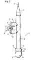
- the internal vibrator 10 comprises a vibrator tube 12 and one in the area of a lower end 14 of the vibrator tube 12 attached cross tube 16. Im Area of an upper end 18 of the vibrating tube 12 is for Example by an elastic sleeve 20 a power cable 22 inserted into the vibrator tube 12.
- the power cord 22 runs through the vibrator tube 12 and forms the Power supply line 24 (in Fig. 1 as dashed lines Line shown) for driving the internal vibrator 10, as described in more detail below.
- a mounting plate 26 for Example attached by welding or the like.
- a Counter plate 28 is temporarily stored by screws 30 and 32 elastic elements 34 and 36 on the plate 26 held.
- On the counter plate 28, one in itself known holding or clamping device 38 can be attached, by means of which the internal vibrator 10, for example on a Concrete layer paver (not shown) may be attached can.
- the vibrator drive is in the central region 40 of the cross tube 16 42 arranged.
- the vibrator drive 42 includes a substantially cylindrical stator core 44, which with its entire outer peripheral surface 46 on the inner surface 48 of the cross tube 16 is tight.
- On both sides of the Stator windings 50 and 52 are provided for stator 44.
- a rotor 54 arranged with a rotor winding 56, in which by those passed through stator windings 50 and 52 AC (or DC if a commutator is provided) Currents and thus with the magnetic field of the stator windings 50 and 52 interacting magnetic field generated becomes.
- the rotor 54 thereby rotates about an axis of rotation A.
- Sections extend on both sides of the rotor 54 58 and 60 of a motor shaft 62.
- the motor shaft 62 is in the area of sections 58 and 60 by bearings 64 and 66 rotatably supported in the cross tube 16.
- each unbalance parts 72 or 74 are each unbalance parts 72 or 74 arranged.
- the unbalance parts 72 and 74 can for example by screws or screw-like end sections of the shaft sections 58 and 60 on the motor shaft 62 removable or adjustable angle.
- each unbalance part exists 72.74 from a plurality of individual unbalance elements 76.
- the two unbalance parts 72 and 74 are in the cross tube 16 arranged such that they are each in the area of the ends 78.80 of the cross tube 16 lie.
- At these ends 78.80 of the Cross tube 16 are each fitted with caps 82, 84.
- the caps 82, 84 close the cross tube 16 tightly, so that no concrete or other liquids can penetrate into the interior of the cross tube 16.
- the Caps 82 and 84 can, for example, by the ends 78, 80 of the cross tube 16 and on the caps 82.84 provided threads each on the cross tube be screwed on.
- the caps 82 and 84 can for example Replace the unbalance parts 72, 74 or to remove or Add individual unbalance elements 76 from cross tube 16 be unscrewed. So it is possible in simpler Way the mass of the unbalance and thus by the Vibrator generated vibration energy or the vibration frequency the vibrator 10 e.g. to the through the adapt the respective concrete type to the specified requirements.
- a lateral substantially cylindrical projection 86 for attaching the Cross tube 16 arranged on the vibrator tube 12. Furthermore, in Area of the lower end 14 of the vibrator tube 12 Provided peripheral flange 88, which in the assembled State of the internal vibrator 10 on an end face 90 of the Approach 86 comes to the plant. In the peripheral flange 88 are Boreholes (not shown) provided by Bolts 92 are penetrated. The bolts 92 engage in holes provided in approach 86 to Example threaded holes (not shown), one and thus hold the cross tube 16 on the vibrator tube 12.
- the power supply line running through the vibrator tube 12 24 runs through section 96 of the vibrator tube 12 and one in the cross tube in line with the opening 87 formed in the approach 86 opening 87 into the interior of the Cross tube 16.
- a recess 98 is provided.
- the power lines 25 can thus, without between Stator 44 and the cross tube 16 to be pinched the windings 50 and 52 are performed, and are simultaneously in the recesses 98 to prevent it from sliding sideways secured.
- each connector connection elements may be arranged, which when installing the vibrator 10, i.e. when inserting of section 96 in the opening 87, a plug connection between the power supply line 24 and that to the stator windings generate leading power lines 25.
- This enables easy manufacture of electrical Connection of the vibrator drive 42 to the power supply line 24 and also attaches when inserting the Vibrator tube 12 in the opening 87 the position of the cross tube 16 to the vibrator tube 12 so that a subsequent Turn the cross tube 16 or the vibrator tube 12 to Do not position the holes for the bolts 92 more is needed.
- FIG. 3 shows an alternative embodiment of the invention Shaker shown.
- parts shown in Figs. 1 and 2 Parts correspond to the first embodiment, with the same reference numerals, each by the number 100 increased, designated.
- the vibrator tube 112 in FIG an area 113 has a curvature.
- the vibrator tube 112 is curved so that the cross tube with the 116th connected portion of the vibrator tube 112 in, for example mounted on a concrete paver Internal vibrator 110 opposes one Direction of movement R of the paver or Internal vibrator extends. So they are on the vibrator tube 112 acting side forces during the forward movement of the internal vibrator 110 through the concrete layer decreased. Even the stress on the fasteners of the internal vibrator 110 is thus reduced. Finally, the in increases accordingly the total area immersed in the concrete layer and hence the vibrator effectiveness.
- Fig. 3 In the embodiment shown in Fig. 3 is in Region of an upper end 117 of the vibrating tube 112 lateral arm 119 is provided, which for attaching the Internal vibrator 110, for example on a concrete paver serves.
- a counter plate 128 is temporarily stored by Spiral spring elements 135 by screw pins 130 and 132 attached to the side arm 119.
- the counter plate 128 is by a clamping plate 129 and bolts 131, 133 in in a known way, for example with a Concrete layer paver firmly connected rod element 137 fixed.
- the cross tube 116 is with the Vibrator tube 112 connected by a screw sleeve 141.
- the side approach 186 points in the area its free end has an external thread, which with an internal thread provided on the cuff 141 interlocking.
- the one provided on the vibrating tube 112 Circumferential flange (not shown) is between one End portion 143 of the sleeve 141 with the smaller, the Corresponding outer diameter of the vibrating tube 112 Diameter and an end face (not shown) of Approach 186 clamped so that the cross tube 116 firmly on Vibrator tube 112 is held.
- the present invention thus makes an internal vibrator provided, which is particularly suitable for operating modes is in which the internal vibrator does not have a certain May be dipped deep into the concrete layer.
- the internal vibrator does not have a certain May be dipped deep into the concrete layer.
- the vibrator drive ensure the generated heat are the vibrator drive and the unbalance in one in the area of the lower end of the Shaker tube arranged cross tube arranged. Damage, caused by overheating the vibrator in the Operation are therefore excluded, because the heat generated in the concrete surrounding the cross tube is dissipated.
- the one provided by the cross tube is enlarged effective surface of the internal vibrator optimal used because directly within this cross tube, and in particular in the end sections of the cross tube leading to Vibrating the concrete required mechanical vibrations generated and delivered.
- Unscrewable caps at the ends of the cross tube allow easy access to each Unbalance parts, so that the unbalance mass or the unbalance angle can be easily changed and thus to the circumstances given by the specific operating conditions can be adjusted.
Landscapes
- Engineering & Computer Science (AREA)
- Mechanical Engineering (AREA)
- Architecture (AREA)
- Civil Engineering (AREA)
- Structural Engineering (AREA)
- On-Site Construction Work That Accompanies The Preparation And Application Of Concrete (AREA)
- Apparatuses For Generation Of Mechanical Vibrations (AREA)
- Ultra Sonic Daignosis Equipment (AREA)
- Glass Compositions (AREA)
- Surgical Instruments (AREA)
Claims (14)
- Vibreur intérieur (10), en particulier pour du béton pas encore durci, comprenant :
un tube de vibreur (12) et un tube transversal (16) placé transversalement au tube de vibreur au niveau d'une extrémité inférieure (14) du tube de vibreur (12), un entraínement de vibreur (42) et une masse de déséquilibre (72, 74) entraínée par l'entraínement de vibreur (42) étant placés dans le tube transversal (16), et une embase latérale (86) pour l'essentiel annulaire s'écartant du tube transversal (16) étant placée de plus dans une zone centrale (40) du tube transversal (16),
caractérisé en ce que, au niveau de l'extrémité inférieure (14), une bride circonférentielle (88) est disposée sur le tube de vibreur (12), bride contre laquelle, après le montage du vibreur intérieur (10), s'appuie une surface frontale (90) de l'embase latérale (86), en ce que le tube transversal (16) est tenu sur le tube de vibreur (12) au moyen de boulons filetés (92) traversant la bride circonférentielle (88), et en ce qu'un tronçon (96) du tube de vibreur (12) formé entre l'extrémité inférieure (14) du tube de vibreur (12) et la bride circonférentielle (88) s'enfonce dans une ouverture (87) formée dans l'embase latérale (86), le diamètre extérieur du tronçon (96) n'étant que légèrement inférieur au diamètre intérieur de l'ouverture (87). - Vibreur intérieur selon la revendication 1, caractérisé en ce que l'entraínement de vibreur (42) est un moteur électrique, comportant un stator (44, 50, 52) placé pour l'essentiel dans la zone centrale (40) du tube transversal (16) et un rotor relié de manière fixe à un arbre moteur (62) et entouré par le stator (44, 50, 52).
- Vibreur intérieur selon la revendication 2, caractérisé en ce que le stator (44, 50, 52) comprend un noyau de stator (44), ainsi qu'au moins un enroulement de stator (50, 52), et est placé avec sa surface circonférentielle extérieure (46) en appui sur toute sa surface contre le tube transversal (16).
- Vibreur intérieur selon la revendication 2 ou 3, caractérisé en ce que l'arbre moteur (62) s'étend pour l'essentiel sur la même distance des deux côtés du rotor (54) et est placé parallèlement au tube transversal (16), de manière que les extrémités (68, 70) de l'arbre moteur (62) se trouvent pour l'essentiel au niveau des extrémités (78, 80) du tube transversal (16).
- Vibreur intérieur selon la revendication 4, caractérisé en ce que l'arbre moteur (62) est monté dans le tube transversal des deux côtés du rotor (54).
- Vibreur intérieur selon la revendication 4 ou 5, caractérisé en ce que la masse de déséquilibre (72, 74) est divisée, une partie (72, 74) de la masse de déséquilibre (72, 74) étant placée respectivement à une extrémité de l'arbre moteur (54).
- Vibreur intérieur selon la revendication 6, caractérisé en ce que chaque partie (72, 74) de la masse de déséquilibre comprend une pluralité d'éléments de déséquilibre (76), qui sont montés amovibles ou selon un angle réglable à l'extrémité respective (68, 70) de l'arbre moteur (62) pour faire varier au choix l'angle de déséquilibre et/ou la masse de déséquilibre.
- Vibreur intérieur selon l'une des revendications 1 à 7, caractérisé en ce qu'aux extrémités (78, 80) du tube transversal (16) sont montés respectivement des capuchons de fermeture amovibles (82, 84), de préférence dévissables.
- Vibreur intérieur selon l'une des revendications 1 à 8, caractérisé en ce que, dans le tube transversal (16), est prévue une ouverture latérale (89) coïncidant pour l'essentiel avec l'ouverture (87) de l'embase annulaire (86).
- Vibreur intérieur selon la revendication 9, caractérisé en ce qu'une ligne d'alimentation électrique (24) passe à travers le tube de vibreur (12) et à travers l'ouverture latérale (89) ménagée dans le tube transversal (16).
- Vibreur intérieur selon la revendication 10, caractérisé en ce que, dans la surface circonférentielle extérieure (46) du stator (44), sont prévus des renfoncements (98) pour passer des lignes électriques (25) en direction des enroulements de stator respectifs (50, 52).
- Vibreur intérieur selon la revendication 10, caractérisé en ce que, dans la surface circonférentielle intérieure du tube transversal, sont prévus des renfoncements pour passer des lignes électriques en direction des enroulements de stator respectifs.
- Vibreur intérieur selon l'une des revendications 10 à 12, caractérisé en ce les lignes électriques (25) sont reliées par une connexion à fiches à la ligne d'alimentation électrique (24) qui passe à travers le tube de vibreur (12).
- Vibreur intérieur selon la revendication 13, caractérisé en ce que la partie de la connexion à fiches qui est reliée à la ligne d'alimentation électrique (24) est placée à l'extrémité inférieure (14) du tube de vibreur (12), et en ce que la partie de la connexion à fiches qui est reliée aux lignes électriques est placée sur le tube transversal (16) au niveau de l'ouverture latérale (89), de sorte que la mise en place du tube transversal (16) sur le tube de vibreur (12) établit automatiquement la connexion à fiches.
Applications Claiming Priority (2)
| Application Number | Priority Date | Filing Date | Title |
|---|---|---|---|
| DE9316430U | 1993-10-27 | ||
| DE9316430U DE9316430U1 (de) | 1993-10-27 | 1993-10-27 | Innenrüttler |
Publications (2)
| Publication Number | Publication Date |
|---|---|
| EP0651114A1 EP0651114A1 (fr) | 1995-05-03 |
| EP0651114B1 true EP0651114B1 (fr) | 1998-01-21 |
Family
ID=6899961
Family Applications (1)
| Application Number | Title | Priority Date | Filing Date |
|---|---|---|---|
| EP94116894A Expired - Lifetime EP0651114B1 (fr) | 1993-10-27 | 1994-10-26 | Vibrateur interne |
Country Status (4)
| Country | Link |
|---|---|
| US (1) | US5529435A (fr) |
| EP (1) | EP0651114B1 (fr) |
| AT (1) | ATE162581T1 (fr) |
| DE (2) | DE9316430U1 (fr) |
Families Citing this family (6)
| Publication number | Priority date | Publication date | Assignee | Title |
|---|---|---|---|---|
| DE19629415C1 (de) * | 1996-06-21 | 1998-05-07 | Teerbau Gmbh Strassenbau | Gleitschalungsfertiger für Betonfahrbahndecken mit speziellen Rüttlerelementen |
| DE202007017018U1 (de) * | 2007-12-04 | 2009-04-09 | Wirtgen Gmbh | Rütteleinrichtung |
| US7887253B2 (en) * | 2008-12-23 | 2011-02-15 | Wirtgen Gmbh | Jolting device |
| JP5953020B2 (ja) * | 2011-04-21 | 2016-07-13 | 株式会社大林組 | バイブレータ |
| CN105970813B (zh) * | 2016-05-16 | 2018-01-05 | 徐建声 | 一种混凝土浇筑振动设备 |
| CN110259135B (zh) * | 2019-05-09 | 2021-05-04 | 昆山市交通航务工程有限公司 | 一种混凝土的振捣设备 |
Family Cites Families (13)
| Publication number | Priority date | Publication date | Assignee | Title |
|---|---|---|---|---|
| US1459841A (en) * | 1919-02-06 | 1923-06-26 | Benjamin A Mitchell | Vibrator for screening machines, etc. |
| GB497425A (en) * | 1936-05-20 | 1938-12-19 | Auguste Goditiabois | Improved apparatus for imparting vibratory motion |
| US2293962A (en) * | 1940-03-25 | 1942-08-25 | Baily Robert William | Oscillator |
| US2289248A (en) * | 1940-06-05 | 1942-07-07 | Kalman Floor Co | Method of treating concrete |
| US2278839A (en) * | 1941-03-29 | 1942-04-07 | Viber Company | Rotor for vibrators |
| US2750160A (en) * | 1952-09-11 | 1956-06-12 | Vibro Plus Corp | Rotary vibrator with a rolling eccentric mass |
| CH439058A (de) * | 1965-01-16 | 1967-06-30 | Losenhausenwerk Duesseldorfer | Innenrüttler |
| DE1684367A1 (de) * | 1967-12-04 | 1970-05-14 | Richard Mueller | Elektromagnetisch angetriebene Vorrichtung zum Verdichten |
| DE2053855A1 (de) * | 1970-11-03 | 1972-05-10 | Kokoschka, Helmut, 6630 Saarlouis | Betonruttier |
| DE2060538C3 (de) * | 1970-12-09 | 1980-08-21 | Robert Bosch Gmbh, 7000 Stuttgart | Innenrüttler |
| DE2525592B2 (de) * | 1975-06-09 | 1977-07-28 | Innenvibrator zum verdichten von beton o.dgl. | |
| US4650366A (en) * | 1986-07-23 | 1987-03-17 | Morrison Donald R | Portable screed |
| JPH0833079B2 (ja) * | 1988-01-29 | 1996-03-29 | 三笠産業株式会社 | コンクリートバイブレータ |
-
1993
- 1993-10-27 DE DE9316430U patent/DE9316430U1/de not_active Expired - Lifetime
-
1994
- 1994-10-25 US US08/329,018 patent/US5529435A/en not_active Expired - Fee Related
- 1994-10-26 EP EP94116894A patent/EP0651114B1/fr not_active Expired - Lifetime
- 1994-10-26 AT AT94116894T patent/ATE162581T1/de active
- 1994-10-26 DE DE59405087T patent/DE59405087D1/de not_active Expired - Lifetime
Also Published As
| Publication number | Publication date |
|---|---|
| EP0651114A1 (fr) | 1995-05-03 |
| US5529435A (en) | 1996-06-25 |
| DE59405087D1 (de) | 1998-02-26 |
| DE9316430U1 (de) | 1994-01-13 |
| ATE162581T1 (de) | 1998-02-15 |
Similar Documents
| Publication | Publication Date | Title |
|---|---|---|
| EP0408988B1 (fr) | Moteur électrique universel | |
| DE102004031605A1 (de) | Motor für elektrische Servolenkungsvorrichtung | |
| DE60017300T2 (de) | Bürstenhalteranordnung für einen Gleichstrommotor | |
| DE10297173T5 (de) | Verkabelungsstruktur für einen Hybridfahrzeugmotor | |
| DE3216978A1 (de) | Kaefiglaeufermotor fuer ein hebezeug, insbesondere fuer einen aufzug | |
| DE102021214732A1 (de) | Elektrische Maschine mit einer mehrteiligen Kopplungsvorrichtung | |
| EP0651114B1 (fr) | Vibrateur interne | |
| DE69016778T2 (de) | Hebevorrichtung für eine dynamoelektrische Maschine. | |
| DE102019113780B4 (de) | Montagewerkzeug für eine Montage und/oder eine Demontage eines Elektromotors | |
| DE19917059B4 (de) | Dynamoelektrische Maschine und Verfahren zu deren Herstellung | |
| EP2343254B1 (fr) | Moteur à tambour | |
| DE8915690U1 (de) | Elektrische Maschine mit vertikaler Welle | |
| DE19517980C2 (de) | Fahrzeugladegenerator | |
| DE102004010209A1 (de) | Rotor einer dynamoelektrischen Maschine | |
| DE2706053A1 (de) | Elektromotorisch angetriebener unwuchtvibrator | |
| DE4342870C1 (de) | Elektrische Maschine, insbesondere Drehstromgenerator | |
| DE19961839A1 (de) | Rohrdrehvorrichtung | |
| EP3587159A2 (fr) | Module de d'entraînement pour un véhicule automobile et procédé de montage et de démontage pour un module d'entraînement | |
| DE19520330A1 (de) | Vorrichtung zum Antreiben eines trommelförmigen Körpers | |
| EP1279363A1 (fr) | Appareil pour la fixation d'un élément de brosses au chassis d'une machine pour nettoyer les sols | |
| DE1944660A1 (de) | Elektromotorisch angetriebene Maschine | |
| EP4429082A1 (fr) | Dispositif d'entraînement pour un véhicule automobile | |
| DE3401152A1 (de) | Abmontierbare brenngarnitur fuer einen nuklearreaktor | |
| EP0730792B1 (fr) | Vibrateur a balourd entraine par un moteur | |
| DE9416348U1 (de) | Wellenverbindung für einen Stromerzeuger |
Legal Events
| Date | Code | Title | Description |
|---|---|---|---|
| PUAI | Public reference made under article 153(3) epc to a published international application that has entered the european phase |
Free format text: ORIGINAL CODE: 0009012 |
|
| AK | Designated contracting states |
Kind code of ref document: A1 Designated state(s): AT BE DE FR GB IT |
|
| 17P | Request for examination filed |
Effective date: 19950505 |
|
| 17Q | First examination report despatched |
Effective date: 19951204 |
|
| GRAG | Despatch of communication of intention to grant |
Free format text: ORIGINAL CODE: EPIDOS AGRA |
|
| GRAG | Despatch of communication of intention to grant |
Free format text: ORIGINAL CODE: EPIDOS AGRA |
|
| GRAG | Despatch of communication of intention to grant |
Free format text: ORIGINAL CODE: EPIDOS AGRA |
|
| GRAH | Despatch of communication of intention to grant a patent |
Free format text: ORIGINAL CODE: EPIDOS IGRA |
|
| GRAH | Despatch of communication of intention to grant a patent |
Free format text: ORIGINAL CODE: EPIDOS IGRA |
|
| GRAA | (expected) grant |
Free format text: ORIGINAL CODE: 0009210 |
|
| AK | Designated contracting states |
Kind code of ref document: B1 Designated state(s): AT BE DE FR GB IT |
|
| PG25 | Lapsed in a contracting state [announced via postgrant information from national office to epo] |
Ref country code: IT Free format text: LAPSE BECAUSE OF FAILURE TO SUBMIT A TRANSLATION OF THE DESCRIPTION OR TO PAY THE FEE WITHIN THE PRE;WARNING: LAPSES OF ITALIAN PATENTS WITH EFFECTIVE DATE BEFORE 2007 MAY HAVE OCCURRED AT ANY TIME BEFORE 2007. THE CORRECT EFFECTIVE DATE MAY BE DIFFERENT FROM THE ONE RECORDED.SCRIBED TIME-LIMIT Effective date: 19980121 Ref country code: GB Free format text: LAPSE BECAUSE OF FAILURE TO SUBMIT A TRANSLATION OF THE DESCRIPTION OR TO PAY THE FEE WITHIN THE PRESCRIBED TIME-LIMIT Effective date: 19980121 Ref country code: FR Free format text: LAPSE BECAUSE OF FAILURE TO SUBMIT A TRANSLATION OF THE DESCRIPTION OR TO PAY THE FEE WITHIN THE PRESCRIBED TIME-LIMIT Effective date: 19980121 |
|
| REF | Corresponds to: |
Ref document number: 162581 Country of ref document: AT Date of ref document: 19980215 Kind code of ref document: T |
|
| REF | Corresponds to: |
Ref document number: 59405087 Country of ref document: DE Date of ref document: 19980226 |
|
| EN | Fr: translation not filed | ||
| GBV | Gb: ep patent (uk) treated as always having been void in accordance with gb section 77(7)/1977 [no translation filed] |
Effective date: 19980121 |
|
| PG25 | Lapsed in a contracting state [announced via postgrant information from national office to epo] |
Ref country code: AT Free format text: LAPSE BECAUSE OF NON-PAYMENT OF DUE FEES Effective date: 19981026 |
|
| PG25 | Lapsed in a contracting state [announced via postgrant information from national office to epo] |
Ref country code: BE Free format text: LAPSE BECAUSE OF NON-PAYMENT OF DUE FEES Effective date: 19981031 |
|
| PLBE | No opposition filed within time limit |
Free format text: ORIGINAL CODE: 0009261 |
|
| STAA | Information on the status of an ep patent application or granted ep patent |
Free format text: STATUS: NO OPPOSITION FILED WITHIN TIME LIMIT |
|
| 26N | No opposition filed | ||
| BERE | Be: lapsed |
Owner name: HEILIT & WOERNER BAU-A.G. Effective date: 19981031 |
|
| PGFP | Annual fee paid to national office [announced via postgrant information from national office to epo] |
Ref country code: DE Payment date: 20091218 Year of fee payment: 16 |
|
| REG | Reference to a national code |
Ref country code: DE Ref legal event code: R119 Ref document number: 59405087 Country of ref document: DE Effective date: 20110502 |
|
| PG25 | Lapsed in a contracting state [announced via postgrant information from national office to epo] |
Ref country code: DE Free format text: LAPSE BECAUSE OF NON-PAYMENT OF DUE FEES Effective date: 20110502 |