EP0651114A1 - Vibrateur interne - Google Patents
Vibrateur interne Download PDFInfo
- Publication number
- EP0651114A1 EP0651114A1 EP94116894A EP94116894A EP0651114A1 EP 0651114 A1 EP0651114 A1 EP 0651114A1 EP 94116894 A EP94116894 A EP 94116894A EP 94116894 A EP94116894 A EP 94116894A EP 0651114 A1 EP0651114 A1 EP 0651114A1
- Authority
- EP
- European Patent Office
- Prior art keywords
- tube
- vibrator
- cross tube
- internal vibrator
- internal
- Prior art date
- Legal status (The legal status is an assumption and is not a legal conclusion. Google has not performed a legal analysis and makes no representation as to the accuracy of the status listed.)
- Granted
Links
- 238000004804 winding Methods 0.000 claims description 16
- 230000002093 peripheral effect Effects 0.000 claims description 15
- 238000007789 sealing Methods 0.000 claims description 4
- 230000000149 penetrating effect Effects 0.000 claims description 2
- 239000007788 liquid Substances 0.000 description 4
- 238000013021 overheating Methods 0.000 description 4
- 238000004519 manufacturing process Methods 0.000 description 3
- 238000004140 cleaning Methods 0.000 description 2
- 238000001816 cooling Methods 0.000 description 2
- 230000007797 corrosion Effects 0.000 description 2
- 238000005260 corrosion Methods 0.000 description 2
- 238000012423 maintenance Methods 0.000 description 2
- 238000003466 welding Methods 0.000 description 2
- 238000005452 bending Methods 0.000 description 1
- 230000005540 biological transmission Effects 0.000 description 1
- 238000010438 heat treatment Methods 0.000 description 1
- 238000007654 immersion Methods 0.000 description 1
- 238000000034 method Methods 0.000 description 1
- 230000008439 repair process Effects 0.000 description 1
- 239000000725 suspension Substances 0.000 description 1
- 230000001960 triggered effect Effects 0.000 description 1
Images

Classifications
-
- B—PERFORMING OPERATIONS; TRANSPORTING
- B06—GENERATING OR TRANSMITTING MECHANICAL VIBRATIONS IN GENERAL
- B06B—METHODS OR APPARATUS FOR GENERATING OR TRANSMITTING MECHANICAL VIBRATIONS OF INFRASONIC, SONIC, OR ULTRASONIC FREQUENCY, e.g. FOR PERFORMING MECHANICAL WORK IN GENERAL
- B06B1/00—Methods or apparatus for generating mechanical vibrations of infrasonic, sonic, or ultrasonic frequency
- B06B1/10—Methods or apparatus for generating mechanical vibrations of infrasonic, sonic, or ultrasonic frequency making use of mechanical energy
- B06B1/16—Methods or apparatus for generating mechanical vibrations of infrasonic, sonic, or ultrasonic frequency making use of mechanical energy operating with systems involving rotary unbalanced masses
- B06B1/161—Adjustable systems, i.e. where amplitude or direction of frequency of vibration can be varied
-
- E—FIXED CONSTRUCTIONS
- E04—BUILDING
- E04G—SCAFFOLDING; FORMS; SHUTTERING; BUILDING IMPLEMENTS OR AIDS, OR THEIR USE; HANDLING BUILDING MATERIALS ON THE SITE; REPAIRING, BREAKING-UP OR OTHER WORK ON EXISTING BUILDINGS
- E04G21/00—Preparing, conveying, or working-up building materials or building elements in situ; Other devices or measures for constructional work
- E04G21/02—Conveying or working-up concrete or similar masses able to be heaped or cast
- E04G21/06—Solidifying concrete, e.g. by application of vacuum before hardening
- E04G21/08—Internal vibrators, e.g. needle vibrators
Definitions
- the present invention relates to an internal vibrator, in particular for not yet hardened concrete, with a vibrator tube, a cross tube attached transversely to the vibrator tube in the area of a lower end of the vibrator tube, a vibrator drive and an imbalance driven by the vibrator drive.
- Such vibrators are known in the prior art and are used to fluidize and solidify freshly poured concrete layers by high-frequency vibrations generated by the internal vibrator.
- the vibrator drive and the unbalance driven by the vibrator drive are arranged in the vibrator tube, which is normally completely immersed in the still liquid concrete layer. Since the vibrator drive and all bearing points of the unbalance are cooled by the concrete surrounding the outer wall of the vibrator tube during operation of the internal vibrator, overheating of the vibrator drive and the bearings of the unbalance is practically impossible.
- a cross tube is attached to the lower end of the vibrator tube, for example by welding.
- This cross tube increases the effective vibrator area and thus the efficiency of the vibrator, so that the vibrating time required for setting the concrete can be significantly reduced.
- the internal vibrators may only be immersed in the upper concrete layer. If the vibrators are also immersed in the sub-concrete layer, there is a risk that dowels provided in the sub-concrete layer will sink too much, and thus will not adequately reinforce the sub-concrete layer. Furthermore, the two concrete layers would be mixed together in an undesirable manner.
- the conventional vibrators are only immersed with their vibrator tip in the concrete layer, and the area of the vibrator tube in which the vibrator drive is arranged is located outdoors. A high failure rate of the vibrator motors was found. The reason for this can be overheating of the vibrator drive or increased corrosion in the internal vibrator during operation and subsequent shutdown due to the high temperature differences occurring in the vibrator.
- the object of the present invention is to provide an internal vibrator in which sufficient cooling of the vibrator drive is ensured even when the internal vibrator is immersed in the concrete to a small extent.
- the object is achieved in that the vibrator drive and the imbalance are arranged in the cross tube.
- This arrangement of the vibrator drive and the unbalance ensures that even at low immersion depths of the internal vibrator in the liquid concrete, which, as mentioned above, is required in the case of two-layer manufacturing processes, which are carried out by the vibrator drive and heat generated in the unbalance bearings can be dissipated by the fluidized concrete surrounding the cross tube and the vibrator tube. Damage to the internal vibrator or the vibrator drive due to overheating and increased corrosion of the internal vibrator triggered by the successive strong heating during operation and cooling after operation can thus be avoided. This avoids downtimes or replacement times before or during vibrator operation, so that the concrete layer can be vibrated quickly and evenly, not affected by failures of the internal vibrators.
- the vibrator drive preferably comprises an electric motor with a stator arranged essentially in the central region of the cross tube and a rotor which is fixedly connected to a motor shaft and surrounded by the stator. It is thus ensured that the heat generated by the electric motor can be dissipated in the same way on both sides of the cross tube. Furthermore, lateral forces caused by an asymmetrical structure of the internal vibrator are avoided.
- stator comprises a stator core and at least one stator winding and is in full contact with its outer circumferential surface on the cross tube, a firm fit of the stator in the cross tube is ensured with optimal use of the space in the cross tube, so that the stator core cannot oscillate relative to the cross tube.
- the motor shaft extends on both sides of the rotor substantially the same distance and is arranged parallel to the cross tube such that the ends of the motor shaft are substantially in the region of the ends of the cross tube, that is in the cross tube for the motor or the motor shaft available space used in an optimal way.
- the motor shaft be mounted on both sides of the rotor in the cross tube.
- the vibrational energy generated by the rotation of the unbalance is optimally transmitted to the entire length of the cross tube, so that the internal vibrator is highly efficient. Furthermore, the symmetrical structure with respect to a longitudinal axis of the vibrator tube ensures that transverse forces occurring during operation of the internal vibrator can be avoided, so that stress on the suspension of the internal vibrator due to such transverse forces can be avoided.
- Each part of the unbalance preferably comprises a plurality of individual unbalance elements which are attached to the respective end of the motor shaft in an angle-adjustable or removable manner for the optional change of the unbalance angle and / or the unbalance mass.
- the vibration energy generated by the internal vibrator can thus be adapted to the respective requirements by changing the unbalanced mass. Furthermore, it is possible to change the natural frequency of the vibration system with a change in the unbalance mass, so that the vibration frequency of the internal vibrator can also be adapted to the respective requirements with as little energy expenditure as possible.
- the attachment or removal or adjustment of the unbalance elements in the region of the ends of the cross tube can be carried out in a particularly simple and quick manner.
- a substantially annular, lateral extension extending away from the cross tube is arranged in a central region of the cross tube, and that a peripheral flange is arranged in the region of the lower end of the vibrating tube , on which in the assembled state of the internal vibrator there is an end face of the side extension, and that the cross tube is held on the vibrating tube by means of screw bolts penetrating the peripheral flange.
- a quick attachment of the cross tube to the vibrating tube is possible in that a portion of the vibrating tube formed between the lower end of the vibrating tube and the peripheral flange projects into an opening formed in the lateral extension, the outside diameter of the portion being only slightly smaller than the inside diameter of the Opening.
- the vibrator tube is only inserted into the opening in the side attachment and turned in the side direction until the corresponding holes for the bolts in the peripheral flange and in the side attachment match.
- the section of the vibrator tube extending into the opening additionally serves to stabilize the connection between the vibrator tube and the cross tube.
- a power supply line preferably runs through the vibrator tube and the lateral opening in the cross tube, so that no additional openings in the vibrator tube or in the cross tube have to be provided, through which power supply lines are led into the corresponding tubes. Entry of moisture through such additional openings can thus be avoided.
- the corresponding power lines can be routed to the corresponding windings in a simple manner and are at the same time secured in the corresponding depressions against external forces.
- the power lines can be arranged in recesses provided in the inner circumferential surface of the cross tube for guiding the power lines to the respective stator windings.
- the power lines be connected by a plug connection to the power supply line running through the vibrating tube. Clamped or soldered connections can thus be dispensed with, so that the exchange or removal of a cross tube including integrated vibrator drive is considerably simplified.
- the part of the plug connection connected to the power supply line is attached to the lower end of the vibrator tube and the part of the plug connection connected to the power lines is in the area of the side Openings are attached to the cross tube, this ensures that the connector is automatically made when attaching to the vibrator tube.
- the plug connection components already fixed on the cross tube or vibrator tube when the cross tube is attached to the vibrator tube, the vibrator tube is already inserted into the cross tube in the correct mounting position, so that the For example, the openings for the screw bolts provided in the peripheral flange of the vibrating tube and in the lateral extension of the cross tube already match, thus additionally facilitating the assembly process.
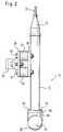
- FIGS. 1 and 2 An internal vibrator shown in FIGS. 1 and 2 is generally designated 10.
- the internal vibrator 10 comprises a vibrator tube 12 and a cross tube 16 attached in the area of a lower end 14 of the vibrator tube 12.
- a power cable 22 is inserted into the vibrator tube 12 through an elastic sleeve 20.
- the power cable 22 runs through the vibrator tube 12 and forms the Power supply line 24 (shown as a dashed line in FIG. 1) for driving the internal vibrator 10, as will be described in more detail below.
- a mounting plate 26 is attached to the vibrator tube 12, for example by welding or the like.
- a counter plate 28 is held on the plate 26 by screws 30 and 32 with the interposition of elastic elements 34 and 36.
- a holding or clamping device 38 known per se can be fastened to the counter plate 28, by means of which the internal vibrator 10 can be attached, for example, to a concrete layer paver (not shown).
- the vibrator drive 42 is arranged in the central region 40 of the cross tube 16.
- the vibrator drive 42 comprises an essentially cylindrical stator core 44 which, with its entire outer peripheral surface 46, bears firmly against the inner surface 48 of the cross tube 16.
- Stator windings 50 and 52 are provided on both sides of the stator 44.
- a rotor 54 Arranged in the cylindrical cavity of the stator 44 is a rotor 54 with a rotor winding 56, in which currents flow through the alternating current (or direct current if a commutator is provided) through the stator windings 50 and 52 and thus interact with the magnetic field of the stator windings 50 and 52 Magnetic field is generated.
- the rotor 54 thereby rotates about an axis of rotation A.
- Sections 58 and 60 of a motor shaft 62 extend on both sides of the rotor 54.
- the motor shaft 62 is rotatably supported in the region of the sections 58 and 60 by bearings 64 and 66 in the cross tube 16.
- unbalance parts 72 and 74 are respectively arranged.
- the unbalance parts 72 and 74 can For example, it can be fixed on the motor shaft 62 such that it can be removed or adjusted in angle by means of screws or screw-like end sections of the shaft sections 58 or 60.
- each unbalance part 72, 74 consists of a plurality of individual unbalance elements 76.
- the two unbalance parts 72 and 74 are arranged in the cross tube 16 in such a way that they are in the region of the ends 78, 80 of the cross tube 16 lie.
- closure caps 82, 84 are attached.
- the caps 82, 84 close the cross tube 16 tightly, so that no concrete or other liquids can penetrate into the interior of the cross tube 16.
- the caps 82 and 84 can be screwed onto the cross tube, for example, by threads provided on the ends 78, 80 of the cross tube 16 and on the caps 82, 84.
- the caps 82 and 84 can be unscrewed from the cross tube 16, for example, to replace the unbalance parts 72, 74 or to remove or add individual unbalance elements 76.
- the caps 82 and 84 can be unscrewed from the cross tube 16, for example, to replace the unbalance parts 72, 74 or to remove or add individual unbalance elements 76.
- a lateral, essentially cylindrical extension 86 for fastening the cross tube 16 to the vibrator tube 12 is arranged in the middle section 40 of the cross tube 16. Furthermore, a peripheral flange 88 is provided in the region of the lower end 14 of the vibrator tube 12, which comes into contact with an end face 90 of the extension 86 in the assembled state of the internal vibrator 10. Bores (not shown) are provided in the circumferential flange 88 and are penetrated by screw bolts 92. The bolts 92 engage in holes provided in the shoulder 86 for Example threaded holes (not shown), and thus hold the cross tube 16 on the vibrating tube 12.
- the vibrating tube 12 in the area of the section 96 has an outer diameter which is only slightly smaller than the inner diameter of the neck 86.
- the vibrator tube 12 with the section 96 can thus simply be pushed into the extension 86 on the cross tube 16. Thereupon, the vibrating tube 12 or cross tube 16 need only be rotated until the holes provided in the peripheral flange 88 match the holes in the shoulder 86.
- the power supply line 24 running through the vibrator tube 12 runs through the section 96 of the vibrator tube 12 and an opening 87 formed in the cross tube in accordance with the opening 87 in the extension 86 into the interior of the cross tube 16.
- the power supply line 24 branches as shown in FIG. 1 shown in dashed lines, in a plurality of power lines 25, which are each led to the individual stator windings 50 and 52.
- the outer circumferential surface 46 of the stator core 44 is for each of the windings 50 and 52, respectively leading power lines a recess 98 is provided.
- the power lines 25 can thus be led to the windings 50 and 52, respectively, without being pinched between the stator 44 and the cross tube 16, and are at the same time secured in the recesses 98 against lateral slipping.
- connector connecting elements can be arranged on the vibrator tube 12 or on the cross tube 16, which are used during the assembly of the internal vibrator 10, i.e. when inserting the section 96 into the opening 87, create a plug connection between the power supply line 24 and the power lines 25 leading to the stator windings.
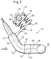
- FIG 3 shows an alternative embodiment of the internal vibrator according to the invention.
- parts which correspond to parts of the first embodiment shown in FIGS. 1 and 2 are denoted by the same reference numerals, each increased by the number 100.
- the vibrating tube 112 has a curvature in a region 113.
- the vibrator tube 112 is curved in such a way that the section of the vibrator tube 112 connected to the transverse tube 116 opposes one another when the internal vibrator 110 is mounted on a concrete paver, for example Direction of movement R of the concrete layer paver or the internal vibrator extends.
- the lateral forces acting on the vibrator tube 112 during the forward movement of the internal vibrator 110 are significantly reduced by the concrete layer.
- the stress on the fastening elements of the internal vibrator 110 is thus also reduced.
- the total area of the vibrator immersed in the concrete layer increases, and with it the effectiveness of the vibrator.
- a lateral arm 119 is provided in the area of an upper end 117 of the vibrator tube 112, which arm is used to attach the internal vibrator 110 to the concrete paver, for example.
- a counter plate 128 is fixed to the side arm 119 with the interposition of spiral spring elements 135 by screw pins 130 and 132.
- the counter plate 128 is fixed by a clamping plate 129 and screw bolts 131, 133 in a manner known per se to a rod element 137, for example firmly connected to a concrete layer paver.
- the lateral arm 119 By arranging the spring elements 135, the lateral arm 119, and thus the internal vibrator 110, can be pivoted under the action of forces with respect to the counter plate 128 fixed to a concrete paver, so that damage, for example bending, of the side arm or of the vibrating tube during operation of the internal vibrator 110 , is avoided.
- the cross tube 116 is connected to the vibrator tube 112 by a screw sleeve 141.
- the lateral extension 186 has an external thread in the area of its free end, which meshes with an internal thread provided on the sleeve 141.
- the circumferential flange (not shown) provided on the vibrating tube 112 is between a End portion 143 of the sleeve 141 with a smaller diameter corresponding to the outer diameter of the vibrating tube 112 and an end face (not shown) of the extension 186 is clamped in, so that the cross tube 116 is held firmly on the vibrating tube 112.
- the power supply line 124 or the power lines 125 are routed inside the vibrator tube 112 or the cross tube, and respective plug connection elements (not shown) can be arranged in the lateral extension 186 or in the vibrator tube 112, which are used when attaching the cross tube 116 on the vibrator tube 112 automatically establish the electrical connection between the power supply line 124 and the power lines 125 leading to the stator windings.
- the present invention thus provides an internal vibrator which is particularly suitable for operating modes in which the internal vibrator must not be immersed in the concrete layer beyond a certain depth.
- the vibrator drive and the imbalance are arranged in a cross tube arranged in the region of the lower end of the vibrator tube. Damage caused by overheating of the internal vibrator during operation is therefore excluded, since the heat generated is dissipated into the concrete surrounding the cross tube.
- the increased effective effective area of the internal vibrator provided by the cross tube is optimally used, since the mechanical vibrations required to vibrate the concrete are generated and emitted directly within this cross tube, and in particular in the end sections of the cross tube.
- Unscrewable caps at the ends of the cross tube allow easy access to the individual unbalance parts, so that the unbalance mass or the unbalance angle can be changed easily and can thus be adapted to the circumstances given by the special operating conditions.
Landscapes
- Engineering & Computer Science (AREA)
- Mechanical Engineering (AREA)
- Architecture (AREA)
- Civil Engineering (AREA)
- Structural Engineering (AREA)
- On-Site Construction Work That Accompanies The Preparation And Application Of Concrete (AREA)
- Apparatuses For Generation Of Mechanical Vibrations (AREA)
- Ultra Sonic Daignosis Equipment (AREA)
- Glass Compositions (AREA)
- Surgical Instruments (AREA)
Applications Claiming Priority (2)
| Application Number | Priority Date | Filing Date | Title |
|---|---|---|---|
| DE9316430U | 1993-10-27 | ||
| DE9316430U DE9316430U1 (de) | 1993-10-27 | 1993-10-27 | Innenrüttler |
Publications (2)
| Publication Number | Publication Date |
|---|---|
| EP0651114A1 true EP0651114A1 (fr) | 1995-05-03 |
| EP0651114B1 EP0651114B1 (fr) | 1998-01-21 |
Family
ID=6899961
Family Applications (1)
| Application Number | Title | Priority Date | Filing Date |
|---|---|---|---|
| EP94116894A Expired - Lifetime EP0651114B1 (fr) | 1993-10-27 | 1994-10-26 | Vibrateur interne |
Country Status (4)
| Country | Link |
|---|---|
| US (1) | US5529435A (fr) |
| EP (1) | EP0651114B1 (fr) |
| AT (1) | ATE162581T1 (fr) |
| DE (2) | DE9316430U1 (fr) |
Cited By (2)
| Publication number | Priority date | Publication date | Assignee | Title |
|---|---|---|---|---|
| DE19629415C1 (de) * | 1996-06-21 | 1998-05-07 | Teerbau Gmbh Strassenbau | Gleitschalungsfertiger für Betonfahrbahndecken mit speziellen Rüttlerelementen |
| CN105970813A (zh) * | 2016-05-16 | 2016-09-28 | 安庆米锐智能科技有限公司 | 一种混凝土浇筑振动设备 |
Families Citing this family (4)
| Publication number | Priority date | Publication date | Assignee | Title |
|---|---|---|---|---|
| DE202007017018U1 (de) * | 2007-12-04 | 2009-04-09 | Wirtgen Gmbh | Rütteleinrichtung |
| US7887253B2 (en) * | 2008-12-23 | 2011-02-15 | Wirtgen Gmbh | Jolting device |
| JP5953020B2 (ja) * | 2011-04-21 | 2016-07-13 | 株式会社大林組 | バイブレータ |
| CN110259135B (zh) * | 2019-05-09 | 2021-05-04 | 昆山市交通航务工程有限公司 | 一种混凝土的振捣设备 |
Citations (3)
| Publication number | Priority date | Publication date | Assignee | Title |
|---|---|---|---|---|
| BE675169A (fr) * | 1965-01-16 | 1966-05-03 | ||
| DE1684367A1 (de) * | 1967-12-04 | 1970-05-14 | Richard Mueller | Elektromagnetisch angetriebene Vorrichtung zum Verdichten |
| DE2053855A1 (de) * | 1970-11-03 | 1972-05-10 | Kokoschka, Helmut, 6630 Saarlouis | Betonruttier |
Family Cites Families (10)
| Publication number | Priority date | Publication date | Assignee | Title |
|---|---|---|---|---|
| US1459841A (en) * | 1919-02-06 | 1923-06-26 | Benjamin A Mitchell | Vibrator for screening machines, etc. |
| GB497425A (en) * | 1936-05-20 | 1938-12-19 | Auguste Goditiabois | Improved apparatus for imparting vibratory motion |
| US2293962A (en) * | 1940-03-25 | 1942-08-25 | Baily Robert William | Oscillator |
| US2289248A (en) * | 1940-06-05 | 1942-07-07 | Kalman Floor Co | Method of treating concrete |
| US2278839A (en) * | 1941-03-29 | 1942-04-07 | Viber Company | Rotor for vibrators |
| US2750160A (en) * | 1952-09-11 | 1956-06-12 | Vibro Plus Corp | Rotary vibrator with a rolling eccentric mass |
| DE2060538C3 (de) * | 1970-12-09 | 1980-08-21 | Robert Bosch Gmbh, 7000 Stuttgart | Innenrüttler |
| DE2525592B2 (de) * | 1975-06-09 | 1977-07-28 | Innenvibrator zum verdichten von beton o.dgl. | |
| US4650366A (en) * | 1986-07-23 | 1987-03-17 | Morrison Donald R | Portable screed |
| JPH0833079B2 (ja) * | 1988-01-29 | 1996-03-29 | 三笠産業株式会社 | コンクリートバイブレータ |
-
1993
- 1993-10-27 DE DE9316430U patent/DE9316430U1/de not_active Expired - Lifetime
-
1994
- 1994-10-25 US US08/329,018 patent/US5529435A/en not_active Expired - Fee Related
- 1994-10-26 EP EP94116894A patent/EP0651114B1/fr not_active Expired - Lifetime
- 1994-10-26 AT AT94116894T patent/ATE162581T1/de active
- 1994-10-26 DE DE59405087T patent/DE59405087D1/de not_active Expired - Lifetime
Patent Citations (3)
| Publication number | Priority date | Publication date | Assignee | Title |
|---|---|---|---|---|
| BE675169A (fr) * | 1965-01-16 | 1966-05-03 | ||
| DE1684367A1 (de) * | 1967-12-04 | 1970-05-14 | Richard Mueller | Elektromagnetisch angetriebene Vorrichtung zum Verdichten |
| DE2053855A1 (de) * | 1970-11-03 | 1972-05-10 | Kokoschka, Helmut, 6630 Saarlouis | Betonruttier |
Cited By (2)
| Publication number | Priority date | Publication date | Assignee | Title |
|---|---|---|---|---|
| DE19629415C1 (de) * | 1996-06-21 | 1998-05-07 | Teerbau Gmbh Strassenbau | Gleitschalungsfertiger für Betonfahrbahndecken mit speziellen Rüttlerelementen |
| CN105970813A (zh) * | 2016-05-16 | 2016-09-28 | 安庆米锐智能科技有限公司 | 一种混凝土浇筑振动设备 |
Also Published As
| Publication number | Publication date |
|---|---|
| US5529435A (en) | 1996-06-25 |
| DE59405087D1 (de) | 1998-02-26 |
| DE9316430U1 (de) | 1994-01-13 |
| EP0651114B1 (fr) | 1998-01-21 |
| ATE162581T1 (de) | 1998-02-15 |
Similar Documents
| Publication | Publication Date | Title |
|---|---|---|
| DE4404791C1 (de) | Baueinheit aus einem Verbrennungsmotor und einem elektrischen Generator | |
| EP0432720B1 (fr) | Tête de bobinage de stator, ensemble de rechange pour celle-ci et méthode pour son remplacement | |
| DE2102679C2 (de) | Elektro-Kleinmotor für einen Lüfter | |
| DE102004031605A1 (de) | Motor für elektrische Servolenkungsvorrichtung | |
| DE102021214732A1 (de) | Elektrische Maschine mit einer mehrteiligen Kopplungsvorrichtung | |
| DE102011000858A1 (de) | Statorkernaufhängungssystem unter Verwendung von Federstäben in einer sich senkrecht zu der Statorkernachse erstreckenden Ebene | |
| DE102016218154A1 (de) | Elektrische Antriebseinheit mit Kühlhülse | |
| EP0651114B1 (fr) | Vibrateur interne | |
| DE69721164T2 (de) | Elektrische Servolenkung | |
| DE2706053A1 (de) | Elektromotorisch angetriebener unwuchtvibrator | |
| EP0960463B1 (fr) | Pompe excentrique entrainee par moteur | |
| DE3704157A1 (de) | Vorrichtung zur geraeuschminderung von elektrischen maschinen | |
| DE8915690U1 (de) | Elektrische Maschine mit vertikaler Welle | |
| DE4342870C1 (de) | Elektrische Maschine, insbesondere Drehstromgenerator | |
| DE68912319T2 (de) | Kraftfahrzeugantrieb mit elektrischen Bremsvorrichtungen. | |
| EP1524751A1 (fr) | Moteur électrique et méthode d'assemblage | |
| EP2845292B1 (fr) | Découplage anti-vibrations du stator d'une machine électrique | |
| DE2301243A1 (de) | Kernhalterung fuer dynamoelektrische maschine | |
| DE19937229A1 (de) | Antriebsvorrichtung für eine Waschmaschine | |
| DE3901905C1 (en) | Device on the commutator of an electrical machine | |
| DE4434221C2 (de) | Motorgetriebener Unwuchtvibrator | |
| EP0418689A2 (fr) | Broche à entraînement individuel | |
| DE10302483B4 (de) | Isolator für ein elektrisch betriebenes Schraubwerkzeug | |
| WO2014048750A2 (fr) | Système d'entraînement électrique de grande dimension | |
| DE102004034119B3 (de) | Webmaschine |
Legal Events
| Date | Code | Title | Description |
|---|---|---|---|
| PUAI | Public reference made under article 153(3) epc to a published international application that has entered the european phase |
Free format text: ORIGINAL CODE: 0009012 |
|
| AK | Designated contracting states |
Kind code of ref document: A1 Designated state(s): AT BE DE FR GB IT |
|
| 17P | Request for examination filed |
Effective date: 19950505 |
|
| 17Q | First examination report despatched |
Effective date: 19951204 |
|
| GRAG | Despatch of communication of intention to grant |
Free format text: ORIGINAL CODE: EPIDOS AGRA |
|
| GRAG | Despatch of communication of intention to grant |
Free format text: ORIGINAL CODE: EPIDOS AGRA |
|
| GRAG | Despatch of communication of intention to grant |
Free format text: ORIGINAL CODE: EPIDOS AGRA |
|
| GRAH | Despatch of communication of intention to grant a patent |
Free format text: ORIGINAL CODE: EPIDOS IGRA |
|
| GRAH | Despatch of communication of intention to grant a patent |
Free format text: ORIGINAL CODE: EPIDOS IGRA |
|
| GRAA | (expected) grant |
Free format text: ORIGINAL CODE: 0009210 |
|
| AK | Designated contracting states |
Kind code of ref document: B1 Designated state(s): AT BE DE FR GB IT |
|
| PG25 | Lapsed in a contracting state [announced via postgrant information from national office to epo] |
Ref country code: IT Free format text: LAPSE BECAUSE OF FAILURE TO SUBMIT A TRANSLATION OF THE DESCRIPTION OR TO PAY THE FEE WITHIN THE PRE;WARNING: LAPSES OF ITALIAN PATENTS WITH EFFECTIVE DATE BEFORE 2007 MAY HAVE OCCURRED AT ANY TIME BEFORE 2007. THE CORRECT EFFECTIVE DATE MAY BE DIFFERENT FROM THE ONE RECORDED.SCRIBED TIME-LIMIT Effective date: 19980121 Ref country code: GB Free format text: LAPSE BECAUSE OF FAILURE TO SUBMIT A TRANSLATION OF THE DESCRIPTION OR TO PAY THE FEE WITHIN THE PRESCRIBED TIME-LIMIT Effective date: 19980121 Ref country code: FR Free format text: LAPSE BECAUSE OF FAILURE TO SUBMIT A TRANSLATION OF THE DESCRIPTION OR TO PAY THE FEE WITHIN THE PRESCRIBED TIME-LIMIT Effective date: 19980121 |
|
| REF | Corresponds to: |
Ref document number: 162581 Country of ref document: AT Date of ref document: 19980215 Kind code of ref document: T |
|
| REF | Corresponds to: |
Ref document number: 59405087 Country of ref document: DE Date of ref document: 19980226 |
|
| EN | Fr: translation not filed | ||
| GBV | Gb: ep patent (uk) treated as always having been void in accordance with gb section 77(7)/1977 [no translation filed] |
Effective date: 19980121 |
|
| PG25 | Lapsed in a contracting state [announced via postgrant information from national office to epo] |
Ref country code: AT Free format text: LAPSE BECAUSE OF NON-PAYMENT OF DUE FEES Effective date: 19981026 |
|
| PG25 | Lapsed in a contracting state [announced via postgrant information from national office to epo] |
Ref country code: BE Free format text: LAPSE BECAUSE OF NON-PAYMENT OF DUE FEES Effective date: 19981031 |
|
| PLBE | No opposition filed within time limit |
Free format text: ORIGINAL CODE: 0009261 |
|
| STAA | Information on the status of an ep patent application or granted ep patent |
Free format text: STATUS: NO OPPOSITION FILED WITHIN TIME LIMIT |
|
| 26N | No opposition filed | ||
| BERE | Be: lapsed |
Owner name: HEILIT & WOERNER BAU-A.G. Effective date: 19981031 |
|
| PGFP | Annual fee paid to national office [announced via postgrant information from national office to epo] |
Ref country code: DE Payment date: 20091218 Year of fee payment: 16 |
|
| REG | Reference to a national code |
Ref country code: DE Ref legal event code: R119 Ref document number: 59405087 Country of ref document: DE Effective date: 20110502 |
|
| PG25 | Lapsed in a contracting state [announced via postgrant information from national office to epo] |
Ref country code: DE Free format text: LAPSE BECAUSE OF NON-PAYMENT OF DUE FEES Effective date: 20110502 |