EP0651143B1 - Dispositif d'entretien pour une transmission automatique - Google Patents
Dispositif d'entretien pour une transmission automatique Download PDFInfo
- Publication number
- EP0651143B1 EP0651143B1 EP94307639A EP94307639A EP0651143B1 EP 0651143 B1 EP0651143 B1 EP 0651143B1 EP 94307639 A EP94307639 A EP 94307639A EP 94307639 A EP94307639 A EP 94307639A EP 0651143 B1 EP0651143 B1 EP 0651143B1
- Authority
- EP
- European Patent Office
- Prior art keywords
- fluid
- transmission
- flow rate
- flow
- pump
- Prior art date
- Legal status (The legal status is an assumption and is not a legal conclusion. Google has not performed a legal analysis and makes no representation as to the accuracy of the status listed.)
- Expired - Lifetime
Links
Images


Classifications
-
- F—MECHANICAL ENGINEERING; LIGHTING; HEATING; WEAPONS; BLASTING
- F16—ENGINEERING ELEMENTS AND UNITS; GENERAL MEASURES FOR PRODUCING AND MAINTAINING EFFECTIVE FUNCTIONING OF MACHINES OR INSTALLATIONS; THERMAL INSULATION IN GENERAL
- F16H—GEARING
- F16H57/00—General details of gearing
- F16H57/04—Features relating to lubrication or cooling or heating
- F16H57/0408—Exchange, draining or filling of transmission lubricant
-
- F—MECHANICAL ENGINEERING; LIGHTING; HEATING; WEAPONS; BLASTING
- F01—MACHINES OR ENGINES IN GENERAL; ENGINE PLANTS IN GENERAL; STEAM ENGINES
- F01M—LUBRICATING OF MACHINES OR ENGINES IN GENERAL; LUBRICATING INTERNAL COMBUSTION ENGINES; CRANKCASE VENTILATING
- F01M11/00—Component parts, details or accessories, not provided for in, or of interest apart from, groups F01M1/00 - F01M9/00
- F01M11/04—Filling or draining lubricant of or from machines or engines
- F01M11/0458—Lubricant filling and draining
-
- F—MECHANICAL ENGINEERING; LIGHTING; HEATING; WEAPONS; BLASTING
- F02—COMBUSTION ENGINES; HOT-GAS OR COMBUSTION-PRODUCT ENGINE PLANTS
- F02B—INTERNAL-COMBUSTION PISTON ENGINES; COMBUSTION ENGINES IN GENERAL
- F02B77/00—Component parts, details or accessories, not otherwise provided for
- F02B77/04—Cleaning of, preventing corrosion or erosion in, or preventing unwanted deposits in, combustion engines
Definitions
- the subject invention relates to vehicle maintenance and, more particularly, to an apparatus for flushing and filling automatic transmissions with transmission fluid. Flushing and filling automatic transmissions with fluid or oil according to prior art methods is a relatively time-consuming and cumbersome process.
- the conventional method is to change the fluid in the pan of the tranmission. The pan typically holds from 1 to 5 litres (1-5 quarts) of the 7 to 15 litres (7-15 quarts) of oil which are in the transmission.
- this conventional service is ineffective, since it mixes new fluid with a large quantity of used fluid.
- More recently there have been efforts to change all the fluid by disconnecting the fluid hose and draining the fluid into a waste oil sump while manually pouring new fluid into the transmission dipstick hole. This procedure has proved inadequate and unsafe, and has resulted in damage to transmissions on which it has been used.
- a device for automating the exchange of fluid in an automatic transmission is disclosed in Japanese patent specification number JP/A/2072299.
- the device is connected in line between upstream and downstream portions of a conduit which circulates fluid from the transmission to an oil cooler.
- the device comprises a tank for receiving used fluid from a drain line connected to an upstream part of the conduit and also a tank of new fluid which is connected to a downstream portion of the conduit by a feed line.
- the device includes a pump for pumping new fluid to the transmission and solenoid controlled valves for opening and closing the drain and feed lines.
- a volume of fluid is first drained from the transmission conduit and measured in a volume meter.
- the drain line valve is then closed and the feed line valve is opened.
- the pump is then activated to pump a metered volume of fluid (corresponding to the volume drained) to the transmission.
- a metered volume of fluid corresponding to the volume drained
- an apparatus for replacing fluid in an automatic transmission wherein said fluid is circulated through a remote cooler via conduits comprising:
- Apparatus which permits used transmission fluid to be withdrawn from the transmission while new or replacement fluid is being simultaneously pumped in.
- the automatic transmission's own fluid pump is employed to pump fluid out of the transmission.
- the flow rate created by that pump is measured and used to set the rate at which a second pump in the apparatus pumps new or replacement fluid into the transmission.
- the present invention also provides a method for replacing fluid in an automatic transmission wherein said fluid is circulated through a remote cooler via conduits, comprising the steps of:
- the automatic transmission flusher apparatus 11 includes first and second hoses 13 and 15. These hoses 13 and 15 are shown entering the engine compartment of an automobile 17.
- cooler lines 21 and 22 extend between the automatic transmission and the radiator 16 of the typical automobile. Fluid is circulated to and through the radiator 16 and back to the transmission in order to cool the fluid.
- the automatic transmission and its internal pump and other componentry may be viewed as a subassembly of the automobile.
- one of these cooler lines 21 is disconnected from the radiator 16.
- the disconnected cooler line 21 is then connected to hose 13, thereby establishing a path for used transmission oil to flow from the transmission into the flusher apparatus 11.
- the second hose 15 of apparatus 11 is connected to the cooler port 19 of the radiator 16 where the line 21 from the transmission now connected to hose 13 was previously connected.
- Other inter-connections of hoses 13 and 15 in the fluid flow path between the transmission and radiator are, of course, consistent with the overall operation described herein.
- line 13 could be hooked at the transmission pump output at which hose 21 is connected.
- the engine of automobile 17 is started.
- the pump associated with the transmission of automobile 17 activates and begins to pump transmission fluid into hose 13.
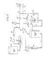
- the flusher apparatus 11 is then activated and begins to simultaneously pump new transmission fluid into the transmission through hose 15, while simultaneously extracting the old transmission fluid through hose 13. This operation will now be described in detail in connection with the detailed drawings of FIGS. 2 and 3.
- the first hose 13 is connected to the hose 21 which normally conducts fluid between the transmission of the automobile 17 and the radiator.
- hose 13 is provided with a suitable hose coupling which mates with the hose coupling of hose 21.
- the fluid flow path through hose 13 to a waste storage tank 33 includes pressure-sensing switch 23, a pressure gauge 25, an electric valve 27, a flow control valve 29, and a sight gas flow meter 31, which provides a visible measurement of flow in litres (gallons) per minute.
- the pressure-sensing switch 23 detects fluid flow in hose 13. When the switch 23 detects fluid flow, it enables operation of the flusher apparatus 11, as hereafter described in more detail in conjunction with FIG. 4.
- the pressure gauge 25 shows the fluid flow pressure in Pascals (pounds per square inch) in hose 13.
- the electric valve 27 either opens or closes the fluid flow path through hose 13 to waste storage tank 33.
- the flow control valve 29 (6.8 x 10 6 Pa (3000 psi)) is manually adjusted to reduce or increase the fluid flow rate.
- the sight glass 31 allows visual indication of fluid flow through hose 15 in gallons per minute (0-20 gallons per minute).
- the fluid flow path for injecting new oil into the transmission through hose 15 includes a fluid holding or storage tank 35 for new (unused) oil, a 12-volt pump 37, a flow control valve 39, a sight glass flow meter 41, a return pressure gauge 43, and a check valve 45.
- the pump 37 When activated, the pump 37 causes transmission fluid to be pumped from the tank 35 through hose 15, and ultimately into the transmission of the automobile 17.
- the sight glass 41 and return pressure gauge 43 allow visual indications of the return pressure and return flow through hose 15 in litres (gallons) per minute and pressure in Pascals (pounds per square inch) (psi), respectively.
- the flow control valve 39 permits the operator of the flusher apparatus to manually adjust the flow rate through hose 15 so that it may match the flow rate at which used transmission fluid is extracted through hose 13.
- the check valve 45 (3.5 x 10 4 Pa to 69 x 10 4 Pa (5 psi to 100 psi)) prevents fluid from coming back down the line.
- the hoses 13 and 15 are appropriately connected. Then the automobile engine is started resulting in activation of the pump associated with the automobile's automatic transmission. This pump begins to pump used transmission fluid into hose 13. Fluid cannot flow into waste storage tan 33, however, because of operation of the electric valve 27, which closes the fluid flow path from hose 13. The fluid flow path from hose 13 remains closed while the pressure in hose 13 is building. The flow control valve 37 on the new fluid side is also normally off or closed at this time.
- the pressure is then read from pressure gauge 25 to give an indication of whether there may be a problem with operation of the transmission pump.
- This pressure reading may initially be 27.5 x 10 4 Pa to 34.5 x 10 4 Pa (40 or 50 psi) above the actual pump pressure.
- Various transmissions have various pump pressures, for example from 3.5 x 10 4 Pa to 20.5 x 10 4 Pa (5 to 30 psi).
- the operator grips the flow control valve 39. Electric valve 27 and the 12-volt pump 37 are then simultaneously activated. Waste transmission fluid then flows from the transmission to the waste storage tank 33. The flow rate to the waste storage tank 33 is read from sight glass 31 and flow control valve 39 is adjusted to achieve the same flow rate. In this manner, old transmission fluid is pumped from the transmission at the same time and at the same rate as new transmission fluid is being injected into the transmission through hose 15.
- the flow control valve 29 in the used fluid path provides for additional adjustment, for example, in case the pressure or flow rate at which used fluid is being pumped exceeds that at which the transmission can accept new fluid from hose 15.
- Drain path 51 includes a drain pump 53 and check valve 55, which connected to hose 15.
- hose 15 is disconnected from port 19 and connected to a suitable drain or waste oil storage facility, and the drain pump 53 is activated, pumping waste fluid from tank 33 to such a suitable drain or waste oil storage facility.
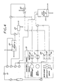
- FIG. 4 Electrical connections of the apparatus according to the preferred embodiment are shown in FIG. 4.
- a 12-volt battery 61 is connected to supply positive power to a three-way toggle switch 65 activated by a switch button 63.
- One pole 64 of the switch 65 is connected to a first terminal of the pressure-sensing switch 23.
- the pressure-sensing switch 23 has a second terminal connected in common to a first terminal of a 12-volt lamp 69 and to a first terminal of the electric valve 27.
- the second terminal of the electric valve 27 is grounded, as is the second terminal of the 12-volt indicator lamp 69.
- the 12-volt power connected to the electrical valve 27 is also connected to a first terminal of the 12-volt pump 37, which has a second terminal connected to ground.
- the apparatus shown in FIGS. 3 and 4 may be conveniently mounted in a portable, wheeled housing, which may be conveniently moved to and from various positions of use and storage.
- the 12-volt battery 61 of FIG. 4 is preferably the vehicle battery electrically interconnected to the electrical circuitry of FIG. 4 by jumper cables leading into the wheeled housing. In this manner, the portability of the unit is enhanced, being independent of electrical outlets or other power interconnections, which may be unavailable.
- FIG. 5 illustrates an alternate embodiment, which omits the sight glasses 31 and 41 of FIG. 3.
- This embodiment operates like that of FIG. 3 in all respects except that omission of the sight glasses is compensated for by visually monitoring the level of the fluid in the dipstick hole and assuring that valves 29 and 39 are adjusted to a flow rate which maintains the fluid level constant, preferably at the "full" mark typically present. Such a check may be made by simply looking into the hole or by monitoring a "wand" or measuring device which extends out of the hole. Such a visual check is also useful and preferably employed during operation of the embodiment of FIG. 3 to assure precise flow rate adjustment.
- the embodiment of FIG. 5 further includes a sight glass 54. As fluid is replaced, one observes the fluid color through sight glass 54. When the color changes from brown to red, the old fluid has been completely replaced and the service is done.
Landscapes
- Engineering & Computer Science (AREA)
- General Engineering & Computer Science (AREA)
- Mechanical Engineering (AREA)
- Chemical & Material Sciences (AREA)
- Combustion & Propulsion (AREA)
- Loading And Unloading Of Fuel Tanks Or Ships (AREA)
- Soil Working Implements (AREA)
- Catching Or Destruction (AREA)
- Massaging Devices (AREA)
- Earth Drilling (AREA)
- Lubrication Of Internal Combustion Engines (AREA)
- Adornments (AREA)
- Control Of Transmission Device (AREA)
Claims (11)
- Appareil pour le remplacement du fluide d'une transmission automatique dans lequel ce fluide circule à travers un refroidisseur (16) distant par des conduits et comportant :un réceptacle (33) pour le fluide usé;une source (35) de fluide frais;une tubulure d'évacuation (13) du fluide usé provenant du côté amont d'un des conduits (21) du réceptacle (33);une tubulure (15) d'amenée du fluide frais de la source (35) au côté aval (19) de ce conduit (21);une pompe (37) disposée entre la source (35) et le côté aval du conduit (21) pour forcer du fluide frais à travers la tubulure (15) d'amenée dans la transmission; caractérisé par le fait qu'au moins une de ces tubulures d'évacuation et d'amenée (13;15) est munie d'une vanne de contrôle du débit (29,39) pour régler le débit de fluide au travers de ces tubulures respectives de manière à équilibrer le débit de fluide usé provenant de la transmission et celui de fluide frais entrant dans la transmission.
- Appareil selon la revendication 1 dans lequel au moins une vanne de contrôle de débit (39) est placée dans la tubulure (15) d'amenée pour régler le flux du fluide frais à travers cette tubulure (15) dans la transmission.
- Appareil selon la revendication 2, comprenant encore une vanne de contrôle du débit (29) dans la tubulure (13) pour régler le flux du fluide usé provenant de la transmission par la tubulure d'évacuation (13).
- Appareil selon l'une des revendications précédentes comportant encore un organe de mesure du débit (31) pour mesurer le débit de fluide usé à partir du côté amont du conduit (21) et un organe de mesure du débit (41) pour mesurer le débit de fluide frais introduit du côté aval de ce conduit (21).
- Appareil selon l'une des revendications précédentes, dans lequel cette pompe (37) est entraínée électriquement.
- Appareil selon la revendication 5, comprenant encore une vanne électrique de fermeture (27) pour contrôler le flux de liquide usé à travers la tubulure d'évacuation (13), l'écoulement étant ouvert après activation.
- Appareil selon la revendication 6, dans lequel cette pompe (37) et cette vanne (27) sont alimentées par une source de puissance à 12V.
- Appareil selon la revendication 6 ou la revendication 7, comportant encore un interrupteur de pression (23) pour activer simultanément la pompe électrique (37) et la vanne électrique (27) dès qu'une pression prédéterminée est détectée dans la tubulure d'évacuation (15).
- Procédé pour remplacer le fluide d'une transmission automatique selon lequel ce fluide est mis en circulation dans un radiateur externe (16) par des conduits (21,22) comportant :l'interception de ce conduit (21) pour connecter le côté amont avec un réceptacle de fluide usé (33), et le côté aval avec une source de fluide frais (35);qu'on provoque l'expulsion du fluide par la pompe de transmission dans ce réceptacle (33) à un débit contrôlé; etqu'on utilise une pompe externe pour introduire le fluide frais de la source (35) dans la transmission par le côté aval du conduit (21) intercepté, caractérisé par le fait que du fluide frais est introduit dans cette transmission à un débit correspondant au débit avec lequel le fluide usé est expulsé dans le réceptacle (33).
- Procédé selon la revendication 9, selon lequel le débit de fluide frais pompé dans la transmission est ajusté au débit du fluide usé expulsé de la transmission par des jauges (31,41) de contrôle mesurant les débits respectifs et ajustant une vanne de réglage de débit (39) située entre la source (35) de fluide frais et le côté aval du conduit (21) intercepté pour effectuer une lecture équilibrée.
- Procédé selon la revendication 9 ou la revendication 10, selon lequel on ajuste une vanne de commande de débit (29) disposée entre le côté amont du conduit (21) intercepté et le réceptacle (33) de fluide usé pour limiter le débit de fluide usé expulsé à un débit auquel il est possible d'introduire le fluide frais dans la transmission.
Applications Claiming Priority (2)
| Application Number | Priority Date | Filing Date | Title |
|---|---|---|---|
| US08145686 US5370160C1 (en) | 1993-02-01 | 1993-10-29 | Apparatus for servicing automatic transmissions and the like |
| US145686 | 1993-10-29 |
Publications (2)
| Publication Number | Publication Date |
|---|---|
| EP0651143A1 EP0651143A1 (fr) | 1995-05-03 |
| EP0651143B1 true EP0651143B1 (fr) | 1999-04-21 |
Family
ID=22514116
Family Applications (1)
| Application Number | Title | Priority Date | Filing Date |
|---|---|---|---|
| EP94307639A Expired - Lifetime EP0651143B1 (fr) | 1993-10-29 | 1994-10-18 | Dispositif d'entretien pour une transmission automatique |
Country Status (5)
| Country | Link |
|---|---|
| US (1) | US5370160C1 (fr) |
| EP (1) | EP0651143B1 (fr) |
| AT (1) | ATE179241T1 (fr) |
| AU (1) | AU673108B2 (fr) |
| DE (1) | DE69417984T2 (fr) |
Families Citing this family (47)
| Publication number | Priority date | Publication date | Assignee | Title |
|---|---|---|---|---|
| US5472064A (en) * | 1994-03-09 | 1995-12-05 | Viken; James P. | Total fluid exchange system for automatic transmissions |
| US6330934B1 (en) | 1991-10-23 | 2001-12-18 | James P. Viken | Complete fluid exchange system for automatic transmissions |
| USRE36650E (en) * | 1991-10-23 | 2000-04-11 | Viken; James P. | Total fluid exchange system for automatic transmissions |
| US6378657B2 (en) | 1991-10-23 | 2002-04-30 | James P. Viken | Fluid exchange system |
| US5626170A (en) * | 1993-02-01 | 1997-05-06 | Flo-Dynamics, Inc. | Automatic transmission fluid changer apparatus |
| FR2718495B1 (fr) * | 1994-04-08 | 1996-06-21 | Aerospatiale | Procédé de remplacement d'un fluide hydraulique contenu dans un circuit de commande tel qu'un circuit d'aéronef. |
| JP2800997B2 (ja) * | 1994-12-15 | 1998-09-21 | 廉正 赤澤 | エンジン冷却液交換装置 |
| US5535849A (en) * | 1995-03-13 | 1996-07-16 | Flo-Dynamics, Inc. | Hand held transmission fluid changer |
| US6223790B1 (en) | 1998-04-29 | 2001-05-01 | James P. Viken | Auto-Loading fluid exchanger and method of use |
| US5915499A (en) * | 1995-10-18 | 1999-06-29 | Flo-Dynamics, Inc. | Apparatus for changing transmission fluid in accordance with a selected condition and method of changing using same |
| US6179018B1 (en) | 1997-01-03 | 2001-01-30 | Bg Products, Inc. | Apparatus and improved method for changing automatic transmission fluid in motor vehicles |
| US5806629A (en) | 1997-03-13 | 1998-09-15 | Wynn Oil Company | Apparatus and method for service of an automotive automatic transmission |
| US5853068A (en) * | 1997-03-21 | 1998-12-29 | Wynn Oil Company | Apparatus for exchange of automotive fluids |
| US6085808A (en) * | 1997-07-23 | 2000-07-11 | Wrr Environmental Services Co., Inc. | Liquid solvent transportation process |
| US9062575B2 (en) * | 1997-10-30 | 2015-06-23 | RPM Industries, LLC | Methods and systems for performing, monitoring and analyzing multiple machine fluid processes |
| US7150286B2 (en) | 1997-10-30 | 2006-12-19 | Rpm Industries, Inc. | Methods and systems for performing, monitoring and analyzing multiple machine fluid processes |
| US5918647A (en) * | 1998-01-21 | 1999-07-06 | Liaw; Bo-Lin | Automatic fluid changing device |
| US6062275A (en) * | 1998-11-02 | 2000-05-16 | Motorvac Technologies, Inc. | Automated replacement of transmission fluid |
| US6360791B2 (en) * | 1998-11-02 | 2002-03-26 | Motorvac Technologies, Inc. | Service equipment for engine cooling systems |
| USRE38232E1 (en) * | 1998-11-02 | 2003-08-26 | Motorvac Technologies, Inc. | Method and apparatus for servicing engine cooling systems |
| US6213175B1 (en) * | 1999-10-25 | 2001-04-10 | Motorvac Technologies, Inc. | Method and apparatus for servicing engine cooling systems |
| US6382271B1 (en) | 1998-11-02 | 2002-05-07 | Motorvac Technologies, Inc. | Apparatus and method for fluid replacement |
| US6035903A (en) * | 1998-12-22 | 2000-03-14 | Flo-Dynamics, Inc. | Self regulating automatic transmission fluid changer |
| US6374872B1 (en) | 1999-03-17 | 2002-04-23 | Mega Products, Inc. | Apparatus for cleaning and flushing a transmission |
| US6244384B1 (en) | 1999-04-27 | 2001-06-12 | Flo-Dynamics, Inc. Llc | Transmission fluid exchanger |
| US6962175B2 (en) * | 1999-04-29 | 2005-11-08 | Viken James P | Pilot valve operated reciprocating fluid exchange device and method of use |
| US6539958B1 (en) * | 2000-10-16 | 2003-04-01 | Motorvac Technologies, Inc. | Cooler flusher |
| US6698472B2 (en) | 2001-02-02 | 2004-03-02 | Moc Products Company, Inc. | Housing for a fluid transfer machine and methods of use |
| US20020148686A1 (en) * | 2001-04-17 | 2002-10-17 | Hwan Yun | Automatic oil changing apparatus for automatic transmission of automobile |
| US6637472B2 (en) | 2001-05-08 | 2003-10-28 | Moc Products Company, Inc. | Coolant transfer machine for automotive vehicle & method |
| US6510876B2 (en) | 2001-05-08 | 2003-01-28 | Moc Products Company, Inc. | Adapter for a coolant transfer machine, methods of transferring coolant and kit |
| US6830082B2 (en) * | 2001-10-29 | 2004-12-14 | Norco Industries, Inc. | Fluid servicing apparatus with dielectric sensing control system |
| US6722398B2 (en) | 2001-10-29 | 2004-04-20 | Norco Industries, Inc. | Integrated automobile fluid servicing apparatus |
| US6729364B2 (en) * | 2001-10-29 | 2004-05-04 | Norco Industries, Inc. | Integrated manifold assembly |
| US6722397B2 (en) | 2001-10-29 | 2004-04-20 | Norco Industries, Inc. | Automotive fluid servicing apparatus |
| US6772802B2 (en) * | 2001-10-29 | 2004-08-10 | Norco Industries Inc. | Fluid servicing apparatus with integrated manifold and pump assembly |
| US6595228B1 (en) * | 2001-11-27 | 2003-07-22 | Motorvac Technologies, Inc. | Vehicle fluid transfer system |
| US6684714B2 (en) * | 2002-05-14 | 2004-02-03 | Spx Corporation | Method and apparatus for testing fluid flow through transmission cooling systems |
| US20050098226A1 (en) * | 2003-11-12 | 2005-05-12 | Rounds Todd M. | Apparatus and method for exchanging vehicular fluids |
| US7179390B1 (en) * | 2005-01-18 | 2007-02-20 | George F Layton | Method of filtering a fluid and remote filtering station |
| USD520523S1 (en) | 2005-03-29 | 2006-05-09 | Motor Components Llc | Portable device for transferring fluids |
| US8746410B1 (en) * | 2008-03-14 | 2014-06-10 | Raymond P. Lekowicz | Outdrive gear oil monitor |
| US9127579B2 (en) * | 2011-08-30 | 2015-09-08 | Timothy E. Miller | Fluid management system |
| US9322306B2 (en) * | 2012-04-25 | 2016-04-26 | Bg Intellectual, Inc. | Transmission fluid exchange machine |
| US10363907B2 (en) * | 2012-04-25 | 2019-07-30 | Bg Intellectuals, Inc. | Fluid exchange machine |
| CN108443452B (zh) * | 2018-03-28 | 2021-06-25 | 广东萨菲洛热能设备有限公司 | 一种循环散热的复合型向心涡轮式液力变矩器 |
| EP3918188B1 (fr) * | 2019-01-28 | 2023-08-09 | Safran Power Units | Système de stockage et de filtration d'huile |
Citations (2)
| Publication number | Priority date | Publication date | Assignee | Title |
|---|---|---|---|---|
| JPH0272299A (ja) * | 1988-09-06 | 1990-03-12 | Mk Seiko Co Ltd | Atf交換装置 |
| WO1994029852A1 (fr) * | 1993-06-11 | 1994-12-22 | Maxtor Corporation | Carte pour une unite de disque dur conforme aux specifications pcmcia et ayant le format type ii |
Family Cites Families (30)
| Publication number | Priority date | Publication date | Assignee | Title |
|---|---|---|---|---|
| US1829173A (en) * | 1928-11-17 | 1931-10-27 | Austin L Wertz | Combined flusher and lubricant dispenser |
| US1884820A (en) * | 1929-08-21 | 1932-10-25 | Osborne Process Inc | Method of cleaning lubricant containers |
| US3216527A (en) * | 1963-02-01 | 1965-11-09 | Exxon Research Engineering Co | Apparatus for changing crankcase oil |
| US3447636A (en) * | 1967-07-24 | 1969-06-03 | Ralph J Bonfilio | Automatic oil exchanging system |
| US3513941A (en) * | 1967-10-20 | 1970-05-26 | Neil J Becnel | Fluid change means for automatic transmissions |
| US3720287A (en) * | 1970-04-01 | 1973-03-13 | M Martel | Crankcase service |
| US3867999A (en) * | 1972-03-15 | 1975-02-25 | Aeroquip Corp | Method and apparatus for changing lube oil |
| JPS51162140U (fr) * | 1975-06-19 | 1976-12-23 | ||
| GB1557204A (en) * | 1976-03-25 | 1979-12-05 | Post Office | Method and apparatus for recycling engine lubricating oil |
| US4095672A (en) * | 1976-04-07 | 1978-06-20 | Atlantic Richfield Company | Apparatus for removal of lubricating composition and methods for using same |
| US4114644A (en) * | 1977-02-08 | 1978-09-19 | Piper Eldon L | Recycling drain pan |
| US4331185A (en) * | 1980-07-14 | 1982-05-25 | Caterpillar Tractor Co. | Transmission filler assembly |
| US4674456A (en) * | 1985-12-13 | 1987-06-23 | Merritt Timothy K | Oil-changing system for an internal combustion engine |
| IT1207638B (it) * | 1987-03-19 | 1989-05-25 | Fiat Trattori Spa | Impianto per il lavaggio interno di un organo in prova |
| US4745989A (en) * | 1987-06-17 | 1988-05-24 | Dimatteo John G | Valve for draining automatic transmission fluid and method of using same |
| US4869346A (en) * | 1987-08-14 | 1989-09-26 | Nelson Donald M | Automatic crankcase oil change and makeup system |
| US4807674A (en) * | 1987-11-23 | 1989-02-28 | Paul A. Braginetz | Vacuum chamber siphon apparatus |
| DE3742821C1 (de) * | 1987-12-17 | 1989-05-24 | Agfa Gevaert Ag | In eine Nassbehandlungsvorrichtung einsetzbarer Vorratskanister fuer Behandlungsfluessigkeiten fuer fotografisches Material |
| JPH0684194B2 (ja) * | 1988-04-14 | 1994-10-26 | 株式会社タツノ・メカトロニクス | オイルチェンジャー |
| US5090458A (en) * | 1988-05-31 | 1992-02-25 | First Brands Corporation | Cleaning apparatus and method |
| US4951784A (en) * | 1989-05-11 | 1990-08-28 | K. J. Manufacturing | Process and device for simple, high speed oil change and/or flushing and air purging of the moving components of the crankcase in an internal combustion engine |
| US5056621A (en) * | 1989-11-09 | 1991-10-15 | Trevino Arnold G | Fluid transfer apparatus and method |
| US5092429A (en) * | 1990-03-15 | 1992-03-03 | Linares Raul F | System for replacing engine lubricant |
| US5062398A (en) * | 1990-04-27 | 1991-11-05 | K. J. Manufacturing | Apparatus and method for changing oil in an internal combustion engine with optional flushing |
| JP2878783B2 (ja) * | 1990-05-02 | 1999-04-05 | ジャトコ株式会社 | 自動変速機のオイル回収装置 |
| WO1992005375A1 (fr) * | 1990-09-18 | 1992-04-02 | Zahnradfabrik Friedrichshafen Ag | Procede et dispositif de renouvellement du lubrifiant dans un organe |
| US5062500A (en) * | 1990-11-28 | 1991-11-05 | Ford New Holland, Inc. | Low profile cart for the insitu collection filteration and recycle of fluids from machinery |
| US5148785A (en) * | 1991-05-28 | 1992-09-22 | Sendak International Corp. | System for removing lubricating oil from an internal combustion engine oil pan |
| US5318080A (en) * | 1991-10-23 | 1994-06-07 | Viken James P | Transmission fluid changer |
| US5337708A (en) * | 1993-06-15 | 1994-08-16 | Chen We Yu | Apparatus and method for automatic transmission system fluid exchange and internal system flushing |
-
1993
- 1993-10-29 US US08145686 patent/US5370160C1/en not_active Expired - Lifetime
-
1994
- 1994-10-18 AT AT94307639T patent/ATE179241T1/de not_active IP Right Cessation
- 1994-10-18 EP EP94307639A patent/EP0651143B1/fr not_active Expired - Lifetime
- 1994-10-18 DE DE69417984T patent/DE69417984T2/de not_active Expired - Fee Related
- 1994-10-27 AU AU77505/94A patent/AU673108B2/en not_active Ceased
Patent Citations (2)
| Publication number | Priority date | Publication date | Assignee | Title |
|---|---|---|---|---|
| JPH0272299A (ja) * | 1988-09-06 | 1990-03-12 | Mk Seiko Co Ltd | Atf交換装置 |
| WO1994029852A1 (fr) * | 1993-06-11 | 1994-12-22 | Maxtor Corporation | Carte pour une unite de disque dur conforme aux specifications pcmcia et ayant le format type ii |
Non-Patent Citations (1)
| Title |
|---|
| PATENT ABSTRACTS OF JAPAN vol. 14, no. 256 (M - 980) * |
Also Published As
| Publication number | Publication date |
|---|---|
| DE69417984D1 (de) | 1999-05-27 |
| US5370160A (en) | 1994-12-06 |
| DE69417984T2 (de) | 1999-08-12 |
| AU7750594A (en) | 1995-06-08 |
| ATE179241T1 (de) | 1999-05-15 |
| EP0651143A1 (fr) | 1995-05-03 |
| AU673108B2 (en) | 1996-10-24 |
| US5370160C1 (en) | 2002-07-16 |
Similar Documents
| Publication | Publication Date | Title |
|---|---|---|
| EP0651143B1 (fr) | Dispositif d'entretien pour une transmission automatique | |
| US5626170A (en) | Automatic transmission fluid changer apparatus | |
| US5535849A (en) | Hand held transmission fluid changer | |
| US5472064A (en) | Total fluid exchange system for automatic transmissions | |
| US6378657B2 (en) | Fluid exchange system | |
| US5787372A (en) | Automated fluid changing system with single-point connection | |
| US5390636A (en) | Coolant transfer apparatus and method, for engine/radiator cooling system | |
| US3867999A (en) | Method and apparatus for changing lube oil | |
| US5000043A (en) | Apparatus and method for testing fuel injectors | |
| US5427202A (en) | Apparatus and method for flushing transmission fluid | |
| JPH0571837B2 (fr) | ||
| US20050166993A1 (en) | Automatic fluid exchanger | |
| CA2284059C (fr) | Appareil et procede d'entretien d'une transmission automatique d'automobile | |
| JPH07504382A (ja) | 流体調和による流体交換器 | |
| US5070831A (en) | Oil change system and method | |
| US6637472B2 (en) | Coolant transfer machine for automotive vehicle & method | |
| US6330934B1 (en) | Complete fluid exchange system for automatic transmissions | |
| US5915499A (en) | Apparatus for changing transmission fluid in accordance with a selected condition and method of changing using same | |
| WO1999005497A1 (fr) | Appareil de test de pression | |
| US5516370A (en) | Can adaptor for fuel system cleaning solvent and method of using same | |
| USRE36650E (en) | Total fluid exchange system for automatic transmissions | |
| CA1167778A (fr) | Systeme de filtration et de recyclage d'huile lubrifiante | |
| US6986283B2 (en) | Method and apparatus for exchanging fluid in a transmission system | |
| CA2149704C (fr) | Appareil utilise dans l'entretien courant de transmissions automatiques et de produits analogues | |
| JP3104743B2 (ja) | 車両の冷却液交換装置及び冷却液交換方法 |
Legal Events
| Date | Code | Title | Description |
|---|---|---|---|
| PUAI | Public reference made under article 153(3) epc to a published international application that has entered the european phase |
Free format text: ORIGINAL CODE: 0009012 |
|
| AK | Designated contracting states |
Kind code of ref document: A1 Designated state(s): AT BE CH DE DK ES FR GB GR IE IT LI LU MC NL PT SE |
|
| RAX | Requested extension states of the european patent have changed |
Free format text: LT;SI |
|
| 17P | Request for examination filed |
Effective date: 19950927 |
|
| RAP1 | Party data changed (applicant data changed or rights of an application transferred) |
Owner name: FLO-DYNAMICS, INC. |
|
| RIN1 | Information on inventor provided before grant (corrected) |
Inventor name: PARKER, ZACHARY T. |
|
| 17Q | First examination report despatched |
Effective date: 19960805 |
|
| GRAG | Despatch of communication of intention to grant |
Free format text: ORIGINAL CODE: EPIDOS AGRA |
|
| GRAG | Despatch of communication of intention to grant |
Free format text: ORIGINAL CODE: EPIDOS AGRA |
|
| GRAH | Despatch of communication of intention to grant a patent |
Free format text: ORIGINAL CODE: EPIDOS IGRA |
|
| GRAH | Despatch of communication of intention to grant a patent |
Free format text: ORIGINAL CODE: EPIDOS IGRA |
|
| GRAA | (expected) grant |
Free format text: ORIGINAL CODE: 0009210 |
|
| AK | Designated contracting states |
Kind code of ref document: B1 Designated state(s): AT BE CH DE DK ES FR GB GR IE IT LI LU MC NL PT SE |
|
| PG25 | Lapsed in a contracting state [announced via postgrant information from national office to epo] |
Ref country code: SE Free format text: THE PATENT HAS BEEN ANNULLED BY A DECISION OF A NATIONAL AUTHORITY Effective date: 19990421 Ref country code: NL Free format text: LAPSE BECAUSE OF FAILURE TO SUBMIT A TRANSLATION OF THE DESCRIPTION OR TO PAY THE FEE WITHIN THE PRESCRIBED TIME-LIMIT Effective date: 19990421 Ref country code: IT Free format text: LAPSE BECAUSE OF FAILURE TO SUBMIT A TRANSLATION OF THE DESCRIPTION OR TO PAY THE FEE WITHIN THE PRE;WARNING: LAPSES OF ITALIAN PATENTS WITH EFFECTIVE DATE BEFORE 2007 MAY HAVE OCCURRED AT ANY TIME BEFORE 2007. THE CORRECT EFFECTIVE DATE MAY BE DIFFERENT FROM THE ONE RECORDED.SCRIBED TIME-LIMIT Effective date: 19990421 Ref country code: GR Free format text: LAPSE BECAUSE OF NON-PAYMENT OF DUE FEES Effective date: 19990421 Ref country code: FR Free format text: LAPSE BECAUSE OF FAILURE TO SUBMIT A TRANSLATION OF THE DESCRIPTION OR TO PAY THE FEE WITHIN THE PRESCRIBED TIME-LIMIT Effective date: 19990421 Ref country code: ES Free format text: THE PATENT HAS BEEN ANNULLED BY A DECISION OF A NATIONAL AUTHORITY Effective date: 19990421 Ref country code: BE Free format text: LAPSE BECAUSE OF FAILURE TO SUBMIT A TRANSLATION OF THE DESCRIPTION OR TO PAY THE FEE WITHIN THE PRESCRIBED TIME-LIMIT Effective date: 19990421 |
|
| REF | Corresponds to: |
Ref document number: 179241 Country of ref document: AT Date of ref document: 19990515 Kind code of ref document: T |
|
| REG | Reference to a national code |
Ref country code: CH Ref legal event code: NV Representative=s name: KIRKER & CIE SA Ref country code: CH Ref legal event code: EP |
|
| REG | Reference to a national code |
Ref country code: IE Ref legal event code: FG4D |
|
| REF | Corresponds to: |
Ref document number: 69417984 Country of ref document: DE Date of ref document: 19990527 |
|
| PG25 | Lapsed in a contracting state [announced via postgrant information from national office to epo] |
Ref country code: DK Free format text: LAPSE BECAUSE OF FAILURE TO SUBMIT A TRANSLATION OF THE DESCRIPTION OR TO PAY THE FEE WITHIN THE PRESCRIBED TIME-LIMIT Effective date: 19990721 |
|
| PG25 | Lapsed in a contracting state [announced via postgrant information from national office to epo] |
Ref country code: PT Free format text: LAPSE BECAUSE OF FAILURE TO SUBMIT A TRANSLATION OF THE DESCRIPTION OR TO PAY THE FEE WITHIN THE PRESCRIBED TIME-LIMIT Effective date: 19990723 |
|
| EN | Fr: translation not filed | ||
| PG25 | Lapsed in a contracting state [announced via postgrant information from national office to epo] |
Ref country code: LU Free format text: LAPSE BECAUSE OF NON-PAYMENT OF DUE FEES Effective date: 19991018 Ref country code: IE Free format text: LAPSE BECAUSE OF NON-PAYMENT OF DUE FEES Effective date: 19991018 Ref country code: AT Free format text: LAPSE BECAUSE OF NON-PAYMENT OF DUE FEES Effective date: 19991018 |
|
| PG25 | Lapsed in a contracting state [announced via postgrant information from national office to epo] |
Ref country code: LI Free format text: LAPSE BECAUSE OF NON-PAYMENT OF DUE FEES Effective date: 19991031 Ref country code: CH Free format text: LAPSE BECAUSE OF NON-PAYMENT OF DUE FEES Effective date: 19991031 |
|
| PLBE | No opposition filed within time limit |
Free format text: ORIGINAL CODE: 0009261 |
|
| STAA | Information on the status of an ep patent application or granted ep patent |
Free format text: STATUS: NO OPPOSITION FILED WITHIN TIME LIMIT |
|
| 26N | No opposition filed | ||
| PG25 | Lapsed in a contracting state [announced via postgrant information from national office to epo] |
Ref country code: MC Free format text: LAPSE BECAUSE OF NON-PAYMENT OF DUE FEES Effective date: 20000430 |
|
| REG | Reference to a national code |
Ref country code: CH Ref legal event code: PL |
|
| REG | Reference to a national code |
Ref country code: IE Ref legal event code: MM4A |
|
| REG | Reference to a national code |
Ref country code: GB Ref legal event code: IF02 |
|
| PGFP | Annual fee paid to national office [announced via postgrant information from national office to epo] |
Ref country code: GB Payment date: 20021009 Year of fee payment: 9 |
|
| PGFP | Annual fee paid to national office [announced via postgrant information from national office to epo] |
Ref country code: DE Payment date: 20021031 Year of fee payment: 9 |
|
| PG25 | Lapsed in a contracting state [announced via postgrant information from national office to epo] |
Ref country code: GB Free format text: LAPSE BECAUSE OF NON-PAYMENT OF DUE FEES Effective date: 20031018 |
|
| PG25 | Lapsed in a contracting state [announced via postgrant information from national office to epo] |
Ref country code: DE Free format text: LAPSE BECAUSE OF NON-PAYMENT OF DUE FEES Effective date: 20040501 |
|
| GBPC | Gb: european patent ceased through non-payment of renewal fee |
Effective date: 20031018 |