EP0651264A2 - Procédé de détection automatique des objets fixes ou en mouvement dans un environnement naturel d'une suite d'images en temps réel - Google Patents
Procédé de détection automatique des objets fixes ou en mouvement dans un environnement naturel d'une suite d'images en temps réel Download PDFInfo
- Publication number
- EP0651264A2 EP0651264A2 EP94115903A EP94115903A EP0651264A2 EP 0651264 A2 EP0651264 A2 EP 0651264A2 EP 94115903 A EP94115903 A EP 94115903A EP 94115903 A EP94115903 A EP 94115903A EP 0651264 A2 EP0651264 A2 EP 0651264A2
- Authority
- EP
- European Patent Office
- Prior art keywords
- image
- matrix
- marked
- determined
- pixel
- Prior art date
- Legal status (The legal status is an assumption and is not a legal conclusion. Google has not performed a legal analysis and makes no representation as to the accuracy of the status listed.)
- Granted
Links
Images


Classifications
-
- G—PHYSICS
- G08—SIGNALLING
- G08B—SIGNALLING SYSTEMS, e.g. PERSONAL CALLING SYSTEMS; ORDER TELEGRAPHS; ALARM SYSTEMS
- G08B13/00—Burglar, theft or intruder alarms
- G08B13/18—Actuation by interference with heat, light, or radiation of shorter wavelength; Actuation by intruding sources of heat, light, or radiation of shorter wavelength
- G08B13/189—Actuation by interference with heat, light, or radiation of shorter wavelength; Actuation by intruding sources of heat, light, or radiation of shorter wavelength using passive radiation detection systems
- G08B13/194—Actuation by interference with heat, light, or radiation of shorter wavelength; Actuation by intruding sources of heat, light, or radiation of shorter wavelength using passive radiation detection systems using image scanning and comparing systems
- G08B13/196—Actuation by interference with heat, light, or radiation of shorter wavelength; Actuation by intruding sources of heat, light, or radiation of shorter wavelength using passive radiation detection systems using image scanning and comparing systems using television cameras
- G08B13/19634—Electrical details of the system, e.g. component blocks for carrying out specific functions
-
- G—PHYSICS
- G01—MEASURING; TESTING
- G01V—GEOPHYSICS; GRAVITATIONAL MEASUREMENTS; DETECTING MASSES OR OBJECTS; TAGS
- G01V8/00—Prospecting or detecting by optical means
- G01V8/10—Detecting, e.g. by using light barriers
-
- G—PHYSICS
- G06—COMPUTING OR CALCULATING; COUNTING
- G06T—IMAGE DATA PROCESSING OR GENERATION, IN GENERAL
- G06T7/00—Image analysis
- G06T7/10—Segmentation; Edge detection
- G06T7/11—Region-based segmentation
-
- G—PHYSICS
- G08—SIGNALLING
- G08B—SIGNALLING SYSTEMS, e.g. PERSONAL CALLING SYSTEMS; ORDER TELEGRAPHS; ALARM SYSTEMS
- G08B13/00—Burglar, theft or intruder alarms
- G08B13/18—Actuation by interference with heat, light, or radiation of shorter wavelength; Actuation by intruding sources of heat, light, or radiation of shorter wavelength
- G08B13/189—Actuation by interference with heat, light, or radiation of shorter wavelength; Actuation by intruding sources of heat, light, or radiation of shorter wavelength using passive radiation detection systems
- G08B13/194—Actuation by interference with heat, light, or radiation of shorter wavelength; Actuation by intruding sources of heat, light, or radiation of shorter wavelength using passive radiation detection systems using image scanning and comparing systems
- G08B13/196—Actuation by interference with heat, light, or radiation of shorter wavelength; Actuation by intruding sources of heat, light, or radiation of shorter wavelength using passive radiation detection systems using image scanning and comparing systems using television cameras
- G08B13/19602—Image analysis to detect motion of the intruder, e.g. by frame subtraction
-
- G—PHYSICS
- G06—COMPUTING OR CALCULATING; COUNTING
- G06T—IMAGE DATA PROCESSING OR GENERATION, IN GENERAL
- G06T2207/00—Indexing scheme for image analysis or image enhancement
- G06T2207/10—Image acquisition modality
- G06T2207/10016—Video; Image sequence
Definitions
- the invention relates to a method according to the preamble of claim 1 and a circuit arrangement for performing the method.
- DE-OS 41 20 676 Such a method is described in DE-OS 41 20 676, which is provided for the detection of small, compact objects in a natural environment with almost complete suppression of irrelevant background information of the image using an electro-optical sensor scanning the environment with a downstream evaluation unit and possibly an image display device .
- the pixel corresponding to the respective matrix center point is marked if, firstly, this pixel is brighter than the maximum of the brightness values of the associated reference quantity by a first threshold value and secondly if the scatter of the associated reference quantity is smaller than a further fixed threshold value, whereby as a measure of the Scatter the brightness values here the difference between maximum and minimum is used.
- the first fixed threshold value denoted for example by T, is incremented or decremented from frame to frame until the criterion N min ⁇ n ⁇ N Max (K3) or T min ⁇ T ⁇ T Max (K4) is satisfied.
- the invention has for its object to provide a method of the type mentioned by which as much information as possible from the digital images is processed, so that the detection of larger fixed or moving objects, which may be generated by different sensors, is made possible .
- the object is achieved by the method steps specified in the characterizing part of claim 1.
- a circuit arrangement for performing the method is claimed in claim 13. Embodiments of these circuit arrangements are described in subclaims 14 to 18.
- the reduction by a factor of 2 produces four similar but not identical images in both directions, depending on the offset of the origin, which has, for example, the coordinates (0,0), (0,1), (1,0), (1, 1) can accept.
- the higher priority objects can be used in a target tracking process to track all significant objects in real time.
- control parameters are the total number of all structured areas (cl) ij with the value zero and the total number of all structured areas (cl) ij with the value 4. These control parameters are called N0 and N4.
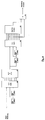
- an FIR filter 1 preferably a 3 ⁇ 3 FIR filter, is provided, to which the digitized image signal of an optronic sensor, not shown in the drawing, is fed via its image input.
- the smoothed image data stream is stored continuously in an image memory 2, preferably operating in tandem, the pixels of the filtered images of a real-time image sequence being addressed by a control device 5.
- a control device 5 z. B. a microprocessor or a digital signal processor with an address generator for the image memory 2 may be provided.
- an image of the real-time image sequence After an image of the real-time image sequence has been read into the memory, it is fed via a time delay circuit 3, for example a 7-line delay block with delay lines the length of one column of the digitized image, to an object and clutter detector 4, which is used for this purpose receives the required threshold values from the control device 5 as a function of intermediate results of the object and clutter detector 4 from the previous image.
- a time delay circuit 3 for example a 7-line delay block with delay lines the length of one column of the digitized image
- an object and clutter detector 4 receives the required threshold values from the control device 5 as a function of intermediate results of the object and clutter detector 4 from the previous image.
- processing takes place several times sequentially depending on the expected object size. If, for example, a digital image of a real-time image sequence is to be analyzed by a reduction factor 2 to a reduction factor n, a total of n + 1 processing runs are required, the image stored in the image memory 2 being addressed pixel by pixel to the
- the results provided by the object and clutter detector namely the coordinates and priorities of the detected objects, are stored in a result memory 6 for each processing run and then merged horizontally and vertically with the aid of the control device 5 in the manner below.
- the coordinates and priorities of the detected objects can be used for further processing, e.g. B. for lane formation, the result memory 6 are removed.
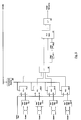
- the object and clutter detector shown in FIG. 2 has an object processor 8, the output of which supplies the object marking with the marking amplitude and a binary image for area marking, and a clutter processor 9 for marking structured areas, i. H. for marking pixels belonging to structured areas. Furthermore, a device for image addressing 10 is provided which controls the threshold sets of the object processor 8 as a function of the above-described and determined position of the horizon and provides the object coordinates at their output.
- a pixel matrix 7 is connected upstream of the inputs of the object processor 8 and the clutter processor 9 and scans the image data stream consisting of seven adjacent columns with four matrices containing several pixels. Each matrix is given a reference quantity outside of the associated matrix center point, the reference quantities of each matrix differing from one another. For example, they can be triangular in shape and arranged at the four corners of a 7 x 7 square matrix.
- the object processor shown in FIG. 3 has four maximum-minimum filters 11.1 to 11.4 arranged in parallel, the inputs of which are connected to the output of the pixel matrix 7 and each of which is supplied with a matrix with an associated reference quantity (clusters 1 to 4) .
- Each filter 11.1 to 11.4 is followed by a control processor 12.1 to 12.4, each control processor 12.1 to 12.4 also being supplied with the pixel corresponding to the respective matrix center point and two threshold values T1 and T2 from a selection threshold 15.1 and 15.2.
- the maximum and minimum of the brightness values of each reference quantity are determined by means of the filters 11.1 to 11.4 and the control processors 12.1 to 12.4.
- the pixel corresponding to the respective center of the matrix is then marked when first this Pixel is brighter than the maximum of the brightness values of the associated reference quantity by a first threshold value and secondly if the scatter of the associated reference quantity is smaller than a further fixed threshold value, the difference between maximum and minimum being used here as a measure for the scattering of the brightness values.
- the outputs of the control processors 12.1 to 12.4 are connected to an event counter 16 and each directly to a first input of four matrices 18.1 to 18.4, the second inputs of the matrices 18.1 to 18.4 via a delay line 17.1, 17.3, 17.5 and 17.7 and the third Inputs of the matrices 18.1 to 18.4 are connected to the output of the assigned control processor 12.1 to 12.4 via two delay lines 17.1, 17.2 to 17.7, 17.8 connected in series.
- the matrices 18.1 to 18.4 are each followed by one of four OR gates 19.1 to 19.4, the outputs of which are connected to an input of an AND gate 20.
- the number of marked pixels of the digital image (intermediate results) for an image is determined by means of these components, and the current count results are compared with an upper and lower fixed barrier and used to regulate the respective first threshold values. Furthermore, the neighboring pixels of each marked pixel of the digital image are marked so that all marked pixels form a dilated set. Subsequently, the dilated quantity elements obtained from a reference quantity are AND-linked with the other dilated quantity elements that each result from a reference quantity.
- the outputs of the OR logic elements 19.1 to 19.4 are also connected to the inputs of an OR logic element 21 for generating binary images for area marking of structured areas which are contained in the digital images of the real-time image sequence. Furthermore is on A third OR gate 22 for the fusion of the horizontal redundancies is connected to the outputs of the AND gate 20, which is arranged downstream of the OR gate 19.1 to 19.2, the second input of this OR gate 22 being connected to the output of an AND gate 24 for controlling the horizontal redundancy fusion is led.
- the circuit arrangement according to FIG. 3 has a total of four threshold value memories 13a, 13b and 14a, 14b, the inputs of which are those from the event counter 16 determined thresholds are supplied and two of which each form a threshold value set 13a and 13b or 14a and 14b.
- Memory 13a is provided for threshold T1 above the horizon
- memory 14b for threshold T2 below the horizon Each threshold value set is followed by a selection threshold 15.1 or 15.2, which are triggered by a horizon control signal which is simultaneously fed to the control input of the event counter 16.
- the threshold values T1 and T2 generated by the selection thresholds 15.1 and 15.2 are present at the threshold value inputs of the control processors 12.1 to 12.4, the horizon control signal driving the selection thresholds 15.1 and 15.2 determining a threshold switchover by, for example, from marked structured areas Position of the horizon can be activated (horizon control).
- the double set of thresholds and event counters enables a better adaptation of the detection sensitivity to a current image scenario.
- the length of the delay line 23 corresponds to the number of pixels within a column reduced by the current reduction factor.
- the image memory 2 is addressed with the aid of the control device 5 so that the reduction factor is 1 in the horizontal direction.
- the AND link 21 in the AND link 24 is controlled by the control device 5 (redundancy fusion) such that the object markings delayed by one column from the delay line 23 merge with the current markings by means of the OR link 22.
- An object that is detected using the described method generates several markings in the binary image stream, depending on the size.
- the additional markings have a disruptive effect on further processing and must therefore be suppressed.
- a marking amplitude is calculated for each object marking, with only the one that is output as the result greater than zero being in the center of a 3 ⁇ 3 environment forms a maximum.
- FIG. 4 for further processing of the binary image of the object marking at the output of the OR logic element 22 there is an input of the matrix 26, a second input of the matrix 26 via a delay line 25.1 of the length of the column of a digital image and a third input of the matrix 26 is connected via two delay lines 25.1 and 25.2 connected in series, each of the length of the column of a digital image.
- the outputs of the matrix 26 are connected to the inputs of a summing element 27 for calculating the marking amplitudes.
- the summing element 27 has two further delay lines 28.1, 28.2 connected in series, a matrix 29 for providing the marking amplitudes, for a maximum detector 30 for marking the amplitude maximum and an AND logic element 31 for suppressing the amplitudes, which do not represent a maximum, and for Subordinate output of the marking amplitude.
- the delay lines 25.1 and 25.2 delay the binary image of the object markings by one column each, so that the center with the 8 neighbors is available simultaneously for each pixel to be processed at the output of the 3 ⁇ 3 matrix 26.
- the values y i are processed using the delay lines 28.1 and 28.2 with the respective column length m and the 3 ⁇ 3 matrix 29 as follows: y i-1-m y i-1 y i-1 + m y im y i y i + m y i + 1-m y i + 1 y i + 1 + m.
- the value y i is determined using the maximum detector 30 and the AND logic element 31 is output as a marking amplitude greater than zero if the following conditions are simultaneously met: (a) y i ⁇ y i-1 + m , (b) y i ⁇ y i + m , (c) y i ⁇ y i + 1 , (d) y i ⁇ y i + 1 + m , (e) y i > y i-1-m , (f) y i > y i-1 , (g) y i > y in the , (H) y i > y i + 1-m .
- the associated pixel is assigned the marker amplitude zero.
- the clutter processor 9 has a number of parallel filters 32.1 to 32.4 corresponding to the examined number of reference quantities, which determine the minima of the brightness values of associated structured areas.
- the outputs of the minimum filters 32.1 to 32.4 are connected to the first inputs of a downstream control processor 33.1 to 33.4, at whose second inputs the pixels corresponding to the respective matrix center points are present, and at whose third inputs the output of a threshold value memory 34 is connected.
- the outputs of the control processors 33.1 to 33.4 are connected to the inputs of an OR gate 35 which fuses the marked pixels of the structured areas to produce a binary image.
- the OR gate 35 are two series-connected delay lines 36.1 to 36.2 each of the length of a column of the digital image and a matrix 37 which, together with the OR gate 38, dilates the binary image in the horizontal and vertical directions to mark the structured areas allows subordinate.
- the minimum Min j is determined with the help of the non-linear filter 32.j and in the control processors 33j compared with the intensity of the pixel corresponding to the respective matrix center.
- the central pixel is marked as belonging to a structured area if the following condition applies: Pix - Min j > Threshold.
Landscapes
- Physics & Mathematics (AREA)
- General Physics & Mathematics (AREA)
- Engineering & Computer Science (AREA)
- Computer Vision & Pattern Recognition (AREA)
- Life Sciences & Earth Sciences (AREA)
- General Life Sciences & Earth Sciences (AREA)
- Geophysics (AREA)
- Theoretical Computer Science (AREA)
- Image Analysis (AREA)
- Image Processing (AREA)
- Closed-Circuit Television Systems (AREA)
Applications Claiming Priority (2)
| Application Number | Priority Date | Filing Date | Title |
|---|---|---|---|
| DE4336751A DE4336751C2 (de) | 1993-10-28 | 1993-10-28 | Verfahren zur automatischen Detektion von festen oder beweglichen Objekten in natürlicher Umgebung einer Echtzeitbildfolge |
| DE4336751 | 1993-10-28 |
Publications (3)
| Publication Number | Publication Date |
|---|---|
| EP0651264A2 true EP0651264A2 (fr) | 1995-05-03 |
| EP0651264A3 EP0651264A3 (fr) | 1997-09-10 |
| EP0651264B1 EP0651264B1 (fr) | 2000-03-08 |
Family
ID=6501197
Family Applications (1)
| Application Number | Title | Priority Date | Filing Date |
|---|---|---|---|
| EP94115903A Expired - Lifetime EP0651264B1 (fr) | 1993-10-28 | 1994-10-08 | Procédé de détection automatique des objets fixes ou en mouvement dans un environnement naturel d'une suite d'images en temps réel |
Country Status (4)
| Country | Link |
|---|---|
| EP (1) | EP0651264B1 (fr) |
| AT (1) | ATE190406T1 (fr) |
| DE (2) | DE4336751C2 (fr) |
| ES (1) | ES2145083T3 (fr) |
Cited By (1)
| Publication number | Priority date | Publication date | Assignee | Title |
|---|---|---|---|---|
| CN119355713A (zh) * | 2024-10-24 | 2025-01-24 | 东莞市芯源集成电路科技发展有限公司 | 基于毫米波雷达与红外热释电传感器双源协同融合的人体存在感知方法 |
Families Citing this family (1)
| Publication number | Priority date | Publication date | Assignee | Title |
|---|---|---|---|---|
| DE4438235B4 (de) * | 1994-10-26 | 2005-04-07 | LFK Lenkflugkörpersysteme GmbH | Verfahren zur automatischen Detektion von kleinen beweglichen Objekten in natürlicher Umgebung, vorzugsweise einer Echtzeitbildfolge |
Family Cites Families (7)
| Publication number | Priority date | Publication date | Assignee | Title |
|---|---|---|---|---|
| GB1605010A (en) * | 1975-01-31 | 1981-12-16 | Mullard Ltd | Picture processing apparatus |
| US4364089A (en) * | 1979-10-31 | 1982-12-14 | Westinghouse Electric Corp. | Binary correlation video tracker |
| US4363089A (en) * | 1979-11-13 | 1982-12-07 | T. B. Wood's Sons Company | Inverter |
| DE3809221A1 (de) * | 1988-03-18 | 1989-09-28 | Roth Electric Gmbh | Verfahren zum detektieren von fehlstellen an pressteilen oder anderen werkstuecken und vorrichtung zur durchfuehrung des verfahrens |
| EP0455898A1 (fr) * | 1990-05-09 | 1991-11-13 | Robert Bishop | Système d'inspection par balayage d'image |
| DE4015173A1 (de) * | 1990-05-11 | 1991-11-14 | Schlafhorst & Co W | Transportsystem fuer auf unabhaengige einzeltraeger senkrecht aufgesetzte spulen oder spulenhuelsen zwischen in der hoehe unterschiedlichen transportebenen |
| DE4120676C2 (de) * | 1991-06-22 | 1994-09-08 | Deutsche Aerospace | Verfahren und Schaltungsanordnung zur Detektion von kleinen Objekten in natürlicher Umgebung |
-
1993
- 1993-10-28 DE DE4336751A patent/DE4336751C2/de not_active Expired - Fee Related
-
1994
- 1994-10-08 EP EP94115903A patent/EP0651264B1/fr not_active Expired - Lifetime
- 1994-10-08 ES ES94115903T patent/ES2145083T3/es not_active Expired - Lifetime
- 1994-10-08 AT AT94115903T patent/ATE190406T1/de not_active IP Right Cessation
- 1994-10-08 DE DE59409182T patent/DE59409182D1/de not_active Expired - Fee Related
Cited By (1)
| Publication number | Priority date | Publication date | Assignee | Title |
|---|---|---|---|---|
| CN119355713A (zh) * | 2024-10-24 | 2025-01-24 | 东莞市芯源集成电路科技发展有限公司 | 基于毫米波雷达与红外热释电传感器双源协同融合的人体存在感知方法 |
Also Published As
| Publication number | Publication date |
|---|---|
| EP0651264B1 (fr) | 2000-03-08 |
| ES2145083T3 (es) | 2000-07-01 |
| DE59409182D1 (de) | 2000-04-13 |
| EP0651264A3 (fr) | 1997-09-10 |
| DE4336751C2 (de) | 2002-04-25 |
| ATE190406T1 (de) | 2000-03-15 |
| DE4336751A1 (de) | 1995-05-18 |
Similar Documents
| Publication | Publication Date | Title |
|---|---|---|
| DE69620125T2 (de) | Gerät zur Bildverarbeitung von Fingerabdrücken | |
| DE69715076T2 (de) | Vorrichtung zur Erzeugung eines Binärbildes | |
| DE69622476T2 (de) | Verfahren und Gerät zur Objekterkennung innerhalb des Gesichtfeldes eines Abbildungsgerätes | |
| DE69530566T2 (de) | Hough-Transform mit Fuzzy-Gradient und Wahl | |
| DE3588169T2 (de) | Verfahren zur Detektion einer Bildbelichtungsfläche in einem Bildauslesevorgang | |
| DE19521346C2 (de) | Bilduntersuchungs/-Erkennungsverfahren, darin verwendetes Verfahren zur Erzeugung von Referenzdaten und Vorrichtungen dafür | |
| DE69129099T2 (de) | Bewegungsausziehverfahren mit der Entstehung von Differenzbildern und einem dreidimensionalen Filter | |
| DE10059895A1 (de) | Verfahren zur Erkennung von Fahrbahnmarkierungen aus Bilddaten | |
| EP2187351A1 (fr) | Procédé et dispositif destinés à la reconnaissance d'objets | |
| EP2028605A1 (fr) | Procédé de détection de formes symétriques | |
| DE102020208080A1 (de) | Erkennung von Objekten in Bildern unter Äquivarianz oder Invarianz gegenüber der Objektgröße | |
| WO2024032856A1 (fr) | Procédé de détermination d'un emplacement de stationnement et d'une position cible pour un véhicule dans l'emplacement de stationnement | |
| DE69507463T2 (de) | Vorrichtung und verfahren zur verkehrsüberwachung | |
| DE3622222A1 (de) | Zeichenerkennung in zweidimensionalen signalen | |
| DE102008050456B4 (de) | Verfahren und Vorrichtung zur Fahrspurerkennung | |
| EP0651264B1 (fr) | Procédé de détection automatique des objets fixes ou en mouvement dans un environnement naturel d'une suite d'images en temps réel | |
| DE112019001959B4 (de) | Segmentieren unregelmässiger formen in bildern unter verwendung von tiefem bereichswachstum | |
| DE69531412T2 (de) | Bildkodierung beruhend auf Bildbereichen und deren segmentierten Randlinien | |
| EP3884427A1 (fr) | Procédé et système de détermination d'un couloir de circulation | |
| DE102007025620A1 (de) | Vorrichtung zur Bestimmung einer Objekt- und/oder Existenzwahrscheinlichtkeit eines Suchobjekts in einem Auslesefenster eines Bildes, Verfahren sowie Computerprogramm | |
| WO1998027511A1 (fr) | Procede et dispositif pour detecter des caracteristiques a partir d'une image, independamment de la situation et de la taille | |
| DE4438235B4 (de) | Verfahren zur automatischen Detektion von kleinen beweglichen Objekten in natürlicher Umgebung, vorzugsweise einer Echtzeitbildfolge | |
| DE19921095B4 (de) | Verfahren und System zur Erfassung von Straßenbereichen | |
| EP0195281B1 (fr) | Circuit de traitement d'images | |
| EP3142068A1 (fr) | Procede de detection tridimensionnelle d'objets |
Legal Events
| Date | Code | Title | Description |
|---|---|---|---|
| PUAI | Public reference made under article 153(3) epc to a published international application that has entered the european phase |
Free format text: ORIGINAL CODE: 0009012 |
|
| AK | Designated contracting states |
Kind code of ref document: A2 Designated state(s): AT DE ES FR GB IT NL SE |
|
| 17P | Request for examination filed |
Effective date: 19960823 |
|
| PUAL | Search report despatched |
Free format text: ORIGINAL CODE: 0009013 |
|
| AK | Designated contracting states |
Kind code of ref document: A3 Designated state(s): AT DE ES FR GB IT NL SE |
|
| RAP1 | Party data changed (applicant data changed or rights of an application transferred) |
Owner name: LFK LENKFLUGKOERPERSYSTEME GMBH |
|
| GRAG | Despatch of communication of intention to grant |
Free format text: ORIGINAL CODE: EPIDOS AGRA |
|
| GRAG | Despatch of communication of intention to grant |
Free format text: ORIGINAL CODE: EPIDOS AGRA |
|
| GRAH | Despatch of communication of intention to grant a patent |
Free format text: ORIGINAL CODE: EPIDOS IGRA |
|
| GRAG | Despatch of communication of intention to grant |
Free format text: ORIGINAL CODE: EPIDOS AGRA |
|
| GRAH | Despatch of communication of intention to grant a patent |
Free format text: ORIGINAL CODE: EPIDOS IGRA |
|
| 17Q | First examination report despatched |
Effective date: 19990811 |
|
| GRAH | Despatch of communication of intention to grant a patent |
Free format text: ORIGINAL CODE: EPIDOS IGRA |
|
| GRAA | (expected) grant |
Free format text: ORIGINAL CODE: 0009210 |
|
| AK | Designated contracting states |
Kind code of ref document: B1 Designated state(s): AT DE ES FR GB IT NL SE |
|
| REF | Corresponds to: |
Ref document number: 190406 Country of ref document: AT Date of ref document: 20000315 Kind code of ref document: T |
|
| ITF | It: translation for a ep patent filed | ||
| REF | Corresponds to: |
Ref document number: 59409182 Country of ref document: DE Date of ref document: 20000413 |
|
| REG | Reference to a national code |
Ref country code: ES Ref legal event code: FG2A Ref document number: 2145083 Country of ref document: ES Kind code of ref document: T3 |
|
| GBT | Gb: translation of ep patent filed (gb section 77(6)(a)/1977) |
Effective date: 20000608 |
|
| ET | Fr: translation filed | ||
| PLBE | No opposition filed within time limit |
Free format text: ORIGINAL CODE: 0009261 |
|
| STAA | Information on the status of an ep patent application or granted ep patent |
Free format text: STATUS: NO OPPOSITION FILED WITHIN TIME LIMIT |
|
| 26N | No opposition filed | ||
| REG | Reference to a national code |
Ref country code: GB Ref legal event code: IF02 |
|
| PGFP | Annual fee paid to national office [announced via postgrant information from national office to epo] |
Ref country code: GB Payment date: 20020925 Year of fee payment: 9 |
|
| PGFP | Annual fee paid to national office [announced via postgrant information from national office to epo] |
Ref country code: NL Payment date: 20020930 Year of fee payment: 9 |
|
| PGFP | Annual fee paid to national office [announced via postgrant information from national office to epo] |
Ref country code: SE Payment date: 20021002 Year of fee payment: 9 |
|
| PGFP | Annual fee paid to national office [announced via postgrant information from national office to epo] |
Ref country code: AT Payment date: 20021003 Year of fee payment: 9 |
|
| PGFP | Annual fee paid to national office [announced via postgrant information from national office to epo] |
Ref country code: FR Payment date: 20021009 Year of fee payment: 9 |
|
| PGFP | Annual fee paid to national office [announced via postgrant information from national office to epo] |
Ref country code: ES Payment date: 20021017 Year of fee payment: 9 Ref country code: DE Payment date: 20021017 Year of fee payment: 9 |
|
| PG25 | Lapsed in a contracting state [announced via postgrant information from national office to epo] |
Ref country code: GB Free format text: LAPSE BECAUSE OF NON-PAYMENT OF DUE FEES Effective date: 20031008 Ref country code: AT Free format text: LAPSE BECAUSE OF NON-PAYMENT OF DUE FEES Effective date: 20031008 |
|
| PG25 | Lapsed in a contracting state [announced via postgrant information from national office to epo] |
Ref country code: SE Free format text: LAPSE BECAUSE OF NON-PAYMENT OF DUE FEES Effective date: 20031009 Ref country code: ES Free format text: LAPSE BECAUSE OF NON-PAYMENT OF DUE FEES Effective date: 20031009 |
|
| PG25 | Lapsed in a contracting state [announced via postgrant information from national office to epo] |
Ref country code: NL Free format text: LAPSE BECAUSE OF NON-PAYMENT OF DUE FEES Effective date: 20040501 Ref country code: DE Free format text: LAPSE BECAUSE OF NON-PAYMENT OF DUE FEES Effective date: 20040501 |
|
| GBPC | Gb: european patent ceased through non-payment of renewal fee |
Effective date: 20031008 |
|
| EUG | Se: european patent has lapsed | ||
| PG25 | Lapsed in a contracting state [announced via postgrant information from national office to epo] |
Ref country code: FR Free format text: LAPSE BECAUSE OF NON-PAYMENT OF DUE FEES Effective date: 20040630 |
|
| NLV4 | Nl: lapsed or anulled due to non-payment of the annual fee |
Effective date: 20040501 |
|
| REG | Reference to a national code |
Ref country code: FR Ref legal event code: ST |
|
| REG | Reference to a national code |
Ref country code: ES Ref legal event code: FD2A Effective date: 20031009 |
|
| PG25 | Lapsed in a contracting state [announced via postgrant information from national office to epo] |
Ref country code: IT Free format text: LAPSE BECAUSE OF NON-PAYMENT OF DUE FEES Effective date: 20051008 |