EP0651521A2 - Procédé pour la discrimination entre bruits et signaux reçus - Google Patents
Procédé pour la discrimination entre bruits et signaux reçus Download PDFInfo
- Publication number
- EP0651521A2 EP0651521A2 EP94307872A EP94307872A EP0651521A2 EP 0651521 A2 EP0651521 A2 EP 0651521A2 EP 94307872 A EP94307872 A EP 94307872A EP 94307872 A EP94307872 A EP 94307872A EP 0651521 A2 EP0651521 A2 EP 0651521A2
- Authority
- EP
- European Patent Office
- Prior art keywords
- signal
- iteration
- samples
- successive
- generating
- Prior art date
- Legal status (The legal status is an assumption and is not a legal conclusion. Google has not performed a legal analysis and makes no representation as to the accuracy of the status listed.)
- Withdrawn
Links
Images

Classifications
-
- H—ELECTRICITY
- H03—ELECTRONIC CIRCUITRY
- H03G—CONTROL OF AMPLIFICATION
- H03G3/00—Gain control in amplifiers or frequency changers
- H03G3/20—Automatic control
- H03G3/30—Automatic control in amplifiers having semiconductor devices
- H03G3/34—Muting amplifier when no signal is present
- H03G3/344—Muting responsive to the amount of noise (noise squelch)
-
- H—ELECTRICITY
- H04—ELECTRIC COMMUNICATION TECHNIQUE
- H04B—TRANSMISSION
- H04B1/00—Details of transmission systems, not covered by a single one of groups H04B3/00 - H04B13/00; Details of transmission systems not characterised by the medium used for transmission
- H04B1/06—Receivers
- H04B1/10—Means associated with receiver for limiting or suppressing noise or interference
- H04B1/1027—Means associated with receiver for limiting or suppressing noise or interference assessing signal quality or detecting noise/interference for the received signal
-
- H—ELECTRICITY
- H04—ELECTRIC COMMUNICATION TECHNIQUE
- H04B—TRANSMISSION
- H04B1/00—Details of transmission systems, not covered by a single one of groups H04B3/00 - H04B13/00; Details of transmission systems not characterised by the medium used for transmission
- H04B1/06—Receivers
- H04B1/10—Means associated with receiver for limiting or suppressing noise or interference
- H04B1/12—Neutralising, balancing, or compensation arrangements
- H04B1/123—Neutralising, balancing, or compensation arrangements using adaptive balancing or compensation means
Definitions
- a receiver In certain types of communications systems. such as systems employed with wireless telephone systems. information conveyed via analog signalling is received by a receiver in a series of encoded representations of information. generally in the form of a series of "1"'s and "0"'s established via frequency shift keying (FSK) at high frequency.
- FSK frequency shift keying
- Such transmissions may be subject to reflection such as from buildings and other objects in the transmission path. so there are sometimes radio frequency (RF) signals arriving at a receiver which are time-delayed with respect to other received signals in a manner which may interrupt or distort reception.
- RF radio frequency
- the demodulator (or decoder) of the receiver may erroneously convert received signals. thereby becoming unstable and producing interference. Such interference is generally perceived by a user of such a system in the form of popping or clicking sounds or other distracting noises.
- Real-time noise discrimination and suppression systems have been designed to quickly discriminate and suppress noise in an incoming signal and to effect muting in a manner which does not prevent understanding received speech when the invention mistakenly triggers on true speech.
- the encoding and decoding method is a method such as Adaptive Differential Pulse Code Modulation ("ADPCM")
- ADPCM Adaptive Differential Pulse Code Modulation
- the decoder may reconstruct the signal in such a way that the decoder output signal is saturated for high amplitude tones and severely clipped for encoded signals that were slightly clipped.
- the noise detection algorithm can falsely trigger the noise suppression algorithm and erroneously mute good tones or speech. Such false triggers can be avoided by reducing the programmed threshold value of the noise detection algorithm. However, reducing the threshold value may reduce the performance of the noise discrimination and detection system in the presence of noise bursts. Such noise bursts may be missed by the system, causing annoying noise signals to be conveyed to the user.
- the apparatus includes a first signal processing means for receiving the received signal and generating a prediction error parameter.
- the apparatus further includes a second signal processing means for receiving the received signal and generating a threshold adjustment value.
- the apparatus still further includes a threshold generating means for generating a threshold value.
- the apparatus still further includes a logic means operatively connected with the first signal processing means, the second signal processing means and the threshold generating means for logically treating the prediction error parameter, the threshold adjustment value and the threshold value to generate a noise indication value.
- the first signal processing means may include first iteration processing means for receiving a first plurality of successive samples of said received signal and generating a first iteration signal, a prediction means operatively connected with said first iteration processing means for receiving said first iteration signal and predicting a next sample value of the first iteration signal, and a comparing means operatively connected with said first iteration processing means and with said prediction means for comparing said first iteration signal with said next sample value and generating the prediction error parameter.
- the second signal processing means may include a second iteration processing means for receiving a second plurality of successive samples of said received signals and generating a second iteration signal responsive to the received signal, and may further include a threshold adjusting means operatively connected with said second iteration processing means for generating a threshold adjustment factor responsive to the second iteration signal.
- the apparatus includes a first signal processing means for receiving the received signal and generating a prediction error parameter.
- the first signal processing means includes a first iteration processing means for generating a first iteration signal, a prediction means for predicting a next sample value of the first iteration signal, and a comparing means for generating the prediction error parameter.
- the first iteration processing means receives a first plurality of successive samples of the received signal and generates a plurality of first iteration signal samples, each successive first iteration signal sample representing a value of a first predetermined number of the first plurality of successive samples of the received signal.
- the prediction means is operatively connected with the first iteration processing means and receives the plurality of first iteration signal samples and generates a plurality of predicted first iteration signal samples. At least one successive predicted first iteration signal sample of the plurality of predicted first iteration signal samples is used for predicting a next successive first iteration signal sample.
- the comparing means is operatively connected with the first iteration processing means and the prediction means and compares the successive first iteration signal samples with the predicted first iteration signal samples, generating the prediction error parameter based upon the comparison.
- the apparatus further includes a second signal processing means for receiving the received signal and generating a threshold adjustment value.
- the second signal processing means includes a second iteration processing means for generating a second iteration signal and a threshold adjusting means for generating a threshold adjustment factor.
- the second iteration processing means receives a second plurality of successive samples of the received signal and generates a plurality of second iteration signal samples. Each successive second iteration signal sample represents a value of a second predetermined number of the second plurality of successive samples of the received signal.
- the threshold adjusting means is operatively connected to the second iteration processing means and generates the threshold adjustment value in response to selected successive second iteration signal samples.
- the apparatus still further includes a threshold generating means for generating a threshold value.
- the apparatus still further includes a logic means operatively connected with the first signal processing means, with the second signal processing means and with the threshold generating means for logically treating the prediction error parameter, the adjustment value, and the threshold value to generate a noise indication value.
- the method includes generating a first plurality of first iteration signal samples, at least one successive first iteration signal sample representing a value of a first plurality of successive samples of the received signal.
- the method further includes generating a second plurality of predicted first iteration signal samples, at least one successive predicted first iteration signal sample predicting a next successive first iteration signal sample.
- the method still further includes comparing the successive first iteration signal samples with the predicted first iteration signal samples and generating a prediction error parameter based upon the comparison.
- the method still further includes generating a plurality of second iteration signal samples, at least one successive second iteration signal sample representing a value of a second predetermined number of the second plurality of successive samples of the received signal.
- the method still further includes generating a threshold adjustment value based upon selected successive second iteration signal samples, and generating a threshold value.
- a logic means is provided for logically treating the prediction error parameter. the threshold adjustment value and the threshold value to generate a noise indication value according to a predetermined logical relationship among the prediction error parameter, the threshold adjustment value and the threshold value.
- Yet another advantage of our system is avoidance of false triggering of the noise suppression algorithm without reducing the programmed threshold value of the noise detection algorithm in a real-time noise discrimination and suppression system.
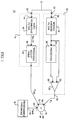
- Fig. 1 is a schematic block diagram of one embodiment of the present invention.
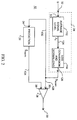
- Fig. 2 is a schematic block diagram of an alternative first signal processing means in Fig. 1.
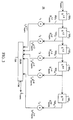
- Fig. 3 is a schematic block diagram of a representative embodiment of the prediction unit of the first signal processing means of Fig. 2.
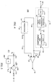
- Fig. 4 is a schematic block diagram of the preferred embodiment of the first signal processing means of Fig. 1.
- Fig. 5 is a schematic block diagram of details of a representative device suitable for use as the signal difference sampling unit of the preferred embodiment shown in Fig. 4 of the first signal processing means of Fig. 1.
- Fig. 6 is a flow diagram illustrating the preferred embodiment of the method of the present invention.
- Fig. 1 is a schematic block diagram of the preferred embodiment of the present invention.
- an apparatus 10 for discriminating signal noise from saturated signals and from high amplitude signals is illustrated as including a first signal processing means 12, a second signal processing means 14, a threshold generating means 16 and a logic means 18.
- the apparatus 10 may be used in a wireless phone system, such as a phone system having no cord connecting the phone receiver and a base unit, the base unit being configured to receive telephone signals by wire or other means.
- a wireless phone system such as a phone system having no cord connecting the phone receiver and a base unit, the base unit being configured to receive telephone signals by wire or other means.
- the input speech received at an input 20 of first processing means 12 and input 22 of second processing means 14 is already band limited to 4 KHz prior to reception by the receiving system.
- This input speech can be received from other sources in other systems, such as recording machines, and may be in linear format or compressed form, having been compressed according to any of several compression algorithms.
- Speech which is in compressed form passes through a normal decoder for the appropriate respective coding system and is then introduced into the audio receiver as linear data.
- Noise detection preferably occurs after the received signal is decoded. No delay need be introduced into the receiving system if such delay is critical to performance or if industry standards preclude any delay. However, if a small amount of delay is used, the early part of a noisy passage of signal can be removed which improves performance.
- First signal processing means 12 includes a first iteration processing means for generating a first iteration signal, such as moving average filter 24, a prediction means for predicting a next sample value of the first iteration signal, such as prediction unit 26, and a comparing means 28 for generating a prediction error parameter, E t , at output 30 of the first signal processing means 12.
- a first iteration processing means for generating a first iteration signal, such as moving average filter 24, a prediction means for predicting a next sample value of the first iteration signal, such as prediction unit 26, and a comparing means 28 for generating a prediction error parameter, E t , at output 30 of the first signal processing means 12.
- the moving average filter 24 receives at its input 32 a first plurality of successive samples of the received incoming signal s.
- the successive samples are preferably successive in time but may be either directly successive (uninterrupted) or indirectly successive (with some samples discarded).
- Moving average filter 24 generates a first plurality of iteration signal samples.
- Each successive iteration signal sample represents a value of a predetermined number of the plurality of successive samples of the incoming signal s.
- the value of the predetermined number of the plurality of successive samples of the received signal may be an average of the number of the plurality of successive samples of the input signal s.
- Prediction unit 26 receives at input 34 the plurality of iteration signal samples generated by moving average filter 24 and generates a plurality of predicted iteration signal samples. Each successive predicted iteration signal sample of the plurality of predicted iteration signal samples is used to predict the next successive iteration signal sample.
- Comparing means 28 receives at first input 36 the plurality of iteration signal samples generated by the moving average filter 24. Comparing means 28 also receives at second input 38 the plurality of predicted iteration signal samples generated by prediction unit 26.
- the comparing means 28 compares the plurality of iteration signal samples with the predicted iteration signal samples. Preferably, the comparison involves a respective successive iteration signal sample and a respective predicted iteration signal sample which are preferably substantially synchronous. Based on this comparison, comparing means 28 generates a prediction error parameter E t based upon the comparison.
- the prediction error parameter E t is supplied to output 30 of the first signal processing means 12.
- first signal processing means 12 will be discussed in detail in connection with Fig. 2.
- the second signal processing means 14 preferably includes a second iteration processing means for generating a second iteration signal, such as auto-regressive filter 40, and a threshold adjusting means for generating a threshold adjustment factor such as threshold adjust table 42.
- the auto-regressive filter 40 receives at input 44 a second plurality of successive samples of the input signal s.
- the successive samples are preferably successive in time but may be either directly successive (uninterrupted) or indirectly successive (with some samples discarded).
- the second plurality of successive signal samples received by auto-regressive filter 40 is the same as the first plurality of successive signal samples received by moving average filter 24.
- auto-regressive filter 40 has a time constant that is longer than the time constant of moving average filter 24.
- Auto-regressive filter 40 generates a second plurality of iteration signal samples.
- Each successive iteration signal sample represents a value of a predetermined number of the plurality of successive samples of the input signal s.
- the predetermined number of successive samples used by auto-regressive filter 40 is greater than the predetermined number of successive samples used by moving average filter 24.
- filter coefficients a and b define a relatively long time constant.
- Threshold adjust table 42 generates a threshold adjust value E adj in response to the generated by auto-regressive filter 40.
- threshold adjust table 42 includes a look-up table.
- the output S av (t) of auto-regressive filter 40 is used as the input to the look-up table of adjustment values. See Table I for exemplary values.
- Table I Step Number Autoregressive Signal Level (Decimal) E thr Adjustment (dB′s) 1 0 - 79 - 0.75 2 80 - 177 - 1.5 3 178 - 245 - 2.25 4 246 - 299 - 3.0 5 300 - 348 - 3.75 6 349 - 399 - 4.5 7 400 - 2047 - 5.25
- the exemplary threshold adjust table 42 of Table I operates in a seven step range where each step reduces the E thr value by 0.75 dB per step.
- Apparatus 10 for discriminating signal noise further includes a threshold generating means for generating a threshold value such as programmed threshold unit 16.
- the generated threshold value E thr is provided to output 48 of the program threshold unit 16.
- Apparatus 10 still further includes logic means 18 for logically treating the prediction error parameter E t , the threshold adjustment value E adj , and the threshold value E thr to generate a noise indication value.
- Logic means 18 has a first input 50 for receiving the prediction error parameter E t , a second input 52 for receiving the threshold adjustment value E adj , and a third input 54 for receiving the threshold value E thr .
- the logic means 18 also has an output 56 for providing the noise indication value.
- the logic means 18 generates the noise indication value when the prediction error parameter is less than the difference between the threshold value and the threshold adjustment value, or when E t ⁇ E thr - E adj .
- protection against false triggering of the apparatus 10 is provided by dynamically adapting the programmed threshold value E thr downward by adjusting E adj so that E t does not become less than the (E thr -E adj ) value.
- the output S av (t) of the auto-regressive filter 40 is used as the input to a look-up table of adjustment values which are subtracted from the programmed E thr value by logic means 18. In this manner, the programmed threshold is adjusted downward as the modulus of the input signal level
- the threshold adjustment made by the auto-regressive filter 40 moves slowly with the output signal S av (t) of auto-regressive filter 40 and prevents the first signal processing means 12 from triggering.
- the amplitude of the received signal s can rise very rapidly. Since the auto-regressive filter 40 preferably has a long time constant, the output of the auto-regressive filter 40 cannot follow the rapid change in the input signal as quickly as can the moving average filter 24. Thus, the adaptive adjustment of the threshold downward is not fast enough to prevent the apparatus 10 from triggering on the noise burst.
- the noise burst is muted whereas clipped speech or high amplitude tones are passed through the apparatus 10 unaffected.
- Fig. 2 is a schematic block diagram of an alternate embodiment of the apparatus of the first signal processing means of Fig. 1.
- a first signal processing means 12 is illustrated as including moving average filter 24, a prediction unit 26, and a comparator unit 28.
- Moving average filter 24 includes signal level averaging unit 112 and log conversion and normalizing unit 114.
- Signal level averaging unit 112 calculates an average signal level ⁇ t , according to the relationship:
- the output of signal level averaging unit 112 varies slowly so that its output can be predicted accurately.
- large errors occur in the prediction of average signal level ⁇ t .
- Such presence of noise in incoming signal s can thus be detected whenever the inverse of prediction error is less than a predetermined threshold level (or, conversely, whenever prediction error is greater than a predetermined threshold level).
- the choice of threshold level can affect the performance of first signal processing means 12 because, if the threshold is set too high, first signal processing means 12 triggers on true speech, and if the threshold is set too low, noise can be missed.
- Signal level averaging unit 112 provides its output ⁇ t to log conversion and normalizing unit 114 via a line 124.
- Incoming signal s is preferably received as a series of "1"'s and "0"'s in the form of a frequency shift keyed (FSK) signal, converted to linear data by a decoder before input to signal level averaging unit 112.
- FSK frequency shift keyed
- Log conversion and normalizing unit 114 performs a conversion of average signal level ⁇ t , according to the known relationship:
- Equations (1) and (2) are preferably simplified for use in a binary arithmetic system and it is desirable that the division functions be removed for convenience, efficiency, and speed in calculation.
- Each incoming signal sample s i is a 16-bit 2's complement number arranged in a format shown below where the arithmetic mask is 19-bit: Bit No. 18 17 16 15 14 13 12 11 10 9 8 7 6 5 4 3 2 1 0 S 15 14 13 12 11 10 9 8 7 6 5 4 3 2 1 where " S " is the sign bit and there are 15 magnitude bits, "bits 15-1".
- Equation (1) requires that the "modulus", or absolute value, of the signal level, or signal strength, of each incoming signal sample s i be generated and added to the previous (n-1) samples of
- ALU arithmetic logic unit
- Equation (2) may be simplified to express S norm in a base 2 logarithm format for more straightforward treatment using a binary system in the form of Equation (3) as shown below:
- Equation (3) simplifies the operation of first signal processing means 12, especially since it avoids division.
- K is a scaling factor, which can be ignored, and K1 is a constant which may be prestored and, therefore, does not require calculation.
- the most significant 16 bits of the ALU in the accumulated format described above are applied to log2 hardware (which is available as a known circuit block); the output of the log2 hardware is an 11-bit plus implied positive sign (12-bit) value stored in a 12-bit format as shown below:
- This log2 value is a signed, 4-bit exponent, 7-bit mantissa parameter where the 4-bit exponent represents the position of the most significant "1" in the 16-bit value ⁇ t .
- the prestored constant K1 may then be subtracted from the output ⁇ t of signal level averaging unit 112 by log conversion and normalizing unit 114 to generate normalized average signal level S norm .
- Normalized average signal level S norm is conveyed via a line 128 to a first input 36 of comparator unit 28, and is conveyed via a line 130 to an input 34 of prediction unit 26.
- Equation (4) may be executed employing an 8 ⁇ 16-bit parallel multiplier where the most significant 16-bits of the S norm parameter (in the 12-bit format described above) are applied to the 16-bit input of the multiplier and the parameters are (prestored as 8-bit signed coefficients) applied to the 8-bit input of the multiplier.
- the output of the multiplier is preferably in the 12-bit format described above (and in log2 format).
- Prediction unit 26 conveys the value of ⁇ norm via a line 134 to a second input 38 of comparator unit 28.
- the apparatus by which prediction unit 26 calculates the value ⁇ norm will be discussed in greater detail hereinafter in connection with Fig. 3.
- Equation (6) K 2 (log2 S norm - log2 [ S norm - S ⁇ norm ])
- Equation (6) requires only two subtractions and two log2 functions, thus simplifying execution of Equation (6) by eliminating any division operations.
- K2 20log102, and is a constant which can be ignored in the preferred exemplary implementation.
- First signal processing means 12 is based upon a signal level prediction and upon an assumption that during normal speech the average signal level varies relatively slowly but channel noise often causes the decoder (from which incoming signal s is received by first signal processing means 12) to become unstable resulting in a large increase in decoded signal level in a much shorter time than is experienced when incoming signal s contains speech information. It is this rapid and large increase in level which is perceived as unpleasant clicks or pops by a user.
- First signal processing means 12 detects the onset of a noise burst whenever the prediction error parameter E t is less than a predetermined threshold. The choice of the threshold directly affects performance and responsiveness of the system, and is generally determined empirically.
- Fig. 3 is a schematic block diagram of a representative embodiment of the prediction unit of the first signal processing means of Fig. 2.
- a prediction unit 26 is illustrated as a multi-stage digital filter comprising a plurality of delay units 1501, 1502, 1503, 1504, ... 150 n .
- Each delay unit 150 i delays the received signal S norm (normalized average signal level) by an additional time period so that an output line 1521 conveys the received signal delayed one time period, S t-1 norm ; output line 1522 conveys the received signal delayed by two time periods, S t-2 norm ; output line 1523 conveys the received signal delayed three time units, S t-3 norm ; output line 1524 conveys the received signal delayed by four time units, S t-4 norm ; and output line 152 n conveys the received signal delayed by n time units, S t-n norm .
- S norm normalized average signal level
- Each of the respective output signals S t-i- norm conveyed by output lines 152 i are respectively multiplied by a scaling factor so that output signal S t-1 norm is multiplied by scaling factor , output signal S t-2 norm is multiplied by scaling factor , output signal S t-3 norm is multiplied by scaling factor , output signal S t-4 norm is multiplied by scaling factor , and output signal S t-n norm is multiplied by scaling factor .
- the resultant scaled output signals are summed in a summer 154 which provides at an output 156 a predicted value ⁇ norm for normalized average signal level S norm based upon a plurality of earlier samples S t-i norm of S norm .
- Fig. 4 is a schematic block diagram of the preferred embodiment of the first signal processing means of Fig. 1.
- an incoming signal s is received by a first signal processing means 200 from the output of a signal decoder (not shown in Fig. 4) by a signal difference sampling unit 211.
- Signal difference sampling unit 211 provides an output which represents the difference between a current sample of incoming signal s with a previous sample of incoming signal s.
- the difference output generated by difference sampling unit 211 is directly related to the rate of change, or slope, of the signal level of incoming signal s at each sampling. This rate of change of signal level is particularly useful in discriminating noise from communications signals, especially speech signals, since the slope of noise signals is significantly different from the slope of speech signals. Noise signals are very easily and, more important, very quickly distinguishable from speech signals by their slope.
- the difference signal output may, for example, be determined by an arrangement such as, the device illustrated in Fig. 5.
- Fig. 5 is a schematic block diagram of details of a representative device suitable for use as the signal difference sampling unit of the preferred embodiment of the first signal processing means illustrated in Fig. 4.
- an incoming signal sample s i is received at a juncture 201.
- Signal sample s i is applied to a delay unit 202 and to the positive node 204 of a summer 206.
- Delay unit 202 generates a delayed (preferably a 1-sample delay) signal sample s i-1
- delayed signal sample s i-1 is applied to a negative node 208 of summer 206.
- Summer 206 generates at an output 210 a difference signal s i -s i-1 .
- Difference signal s i -s i-1 is received by signal difference level averaging unit 212 at input 22 (Fig. 4).
- Signal difference level averaging unit 212 calculates an average difference signal level ⁇ t , preferably according to the relationship: where
- signal difference level averaging unit 212 varies slowly so that its output can be predicted accurately.
- large errors occur in the prediction of average difference signal level ⁇ t .
- Such presence of noise in incoming signal s can thus be detected whenever the inverse of prediction error is less than a predetermined threshold level (or, conversely, whenever prediction error is greater than a predetermined threshold level).
- signal difference level averaging unit 212 provides its output ⁇ t to log conversion and normalizing unit 114 via a line 124.
- Average signal level ⁇ t is provided to log conversion and normalizing unit 114 via a line 124.
- Incoming signal s is preferably received as a series of "1"'s and "0"'s in the form of a frequency shift keyed (FSK) signal, converted to linear data by a decoder before input to signal difference sampling unit 211.
- FSK frequency shift keyed
- Log conversion and normalizing unit 114 performs a conversion of average difference signal level ⁇ t , preferably according to the known relationship:
- Equation (12) may be simplified to express ⁇ S norm in a base 2 logarithm format for more straightforward treatment using a binary system in the form of Equation (13) as shown below:
- Equation (9) simplifies the operation of apparatus 200, especially since it avoids division.
- K is a scaling factor, which can be ignored, and K1 is a constant which may be prestored and, therefore, does not require calculation.
- the prestored constant K1 may be subtracted from the output ⁇ t of signal difference level averaging unit 212 by log conversion and normalizing unit 114 to generate normalized average difference signal level ⁇ S norm .
- Normalized average difference signal level ⁇ S norm is conveyed via a line 128 to a first input 136 of comparator unit 28, and is conveyed via a line 130 to an input 34 of prediction unit 26.
- the four past scaled values of ⁇ S norm are represented by and are accumulated in prediction unit 26. Equation (10) may be executed employing an 8 ⁇ 16-bit parallel multiplier where the most significant 16-bits of the ⁇ S norm parameter (in the 12-bit format described above) are applied to the 16-bit input of the multiplier and the parameters are (prestored as 8-bit signed coefficients) applied to the 8-bit input of the multiplier.
- the output of the multiplier is preferably in the 12-bit format described above (and in log2 format).
- Prediction unit 26 conveys the value of ⁇ norm via a line 134 to a second input 38 of comparator unit 28.
- the apparatus by which prediction unit 26 calculates the value ⁇ norm was discussed in connection with Fig. 3.
- Equation (16) Equation (16) requires only two subtractions and two log2 functions, thus simplifying execution of Equation (16) by eliminating any division operations.
- K2 20log102, and is a constant which can be ignored in the preferred exemplary implementation.
- the remainder of the preferred embodiment of the first signal processing means is constructed and operates in substantially the same manner as has been previously described in connection with Figs. 1-3.
- Fig. 6 is a flow diagram illustrating the preferred embodiment of the method of the present invention.
- the method starts at a block 60 with reception of incoming signal s (see Fig. 5).
- the first iteration signal sample is calculated.
- a plurality of first iteration signal samples is generated from the input signal.
- Each successive iteration signal sample represents a value of a first predetermined number of samples of a plurality of successive samples of the received signal.
- the value of the first predetermined number is an average of the first predetermined number of successive samples of the received signal.
- a moving average signal performs the calculations.
- a plurality of predicted first iteration signals is generated. Each successive predicted first iteration signal sample is used to predict a next successive first iteration signal sample.
- the first iteration signal samples calculated at block 62 and the predicted first iteration signal samples calculated at block 64 are compared.
- a prediction error parameter, designated E t is generated based upon the comparison.
- the comparison involves a respective successive first iteration signal sample and a respective predicted first iteration signal sample which are substantially synchronous.
- a plurality of second iteration signal samples is calculated from the input signal.
- Each successive second iteration signal sample represents a value of a second predetermined number of samples of a plurality of successive samples of the received signal.
- the second predetermined number of samples is greater than the first predetermined number of samples.
- a threshold adjustment value, E adj is calculated based upon selected second iteration signal samples.
- a threshold adjusting means such as a look-up table responsive to the selected second iteration signal samples is provided.
- a threshold value is generated, and at block 74, a logic means is provided to determine whether to generate a noise indication according to a predetermined logical relationship among the prediction error parameter, the threshold adjustment value and the threshold value. Preferably, if E t ⁇ E thr - E adj , the noise indication value is generated at block 76.
Landscapes
- Engineering & Computer Science (AREA)
- Computer Networks & Wireless Communication (AREA)
- Signal Processing (AREA)
- Noise Elimination (AREA)
- Dc Digital Transmission (AREA)
Applications Claiming Priority (2)
| Application Number | Priority Date | Filing Date | Title |
|---|---|---|---|
| US08/152,316 US5507037A (en) | 1992-05-22 | 1993-11-03 | Apparatus and method for discriminating signal noise from saturated signals and from high amplitude signals |
| US152316 | 1993-11-03 |
Publications (2)
| Publication Number | Publication Date |
|---|---|
| EP0651521A2 true EP0651521A2 (fr) | 1995-05-03 |
| EP0651521A3 EP0651521A3 (fr) | 1999-11-24 |
Family
ID=22542411
Family Applications (1)
| Application Number | Title | Priority Date | Filing Date |
|---|---|---|---|
| EP94307872A Withdrawn EP0651521A3 (fr) | 1993-11-03 | 1994-10-26 | Procédé pour la discrimination entre bruits et signaux reçus |
Country Status (3)
| Country | Link |
|---|---|
| US (1) | US5507037A (fr) |
| EP (1) | EP0651521A3 (fr) |
| JP (1) | JPH07193520A (fr) |
Cited By (4)
| Publication number | Priority date | Publication date | Assignee | Title |
|---|---|---|---|---|
| WO2000031882A1 (fr) * | 1998-11-24 | 2000-06-02 | Robert Bosch Gmbh | Procede et dispositif pour reconnaitre et eliminer des impulsions parasites dans un signal utile |
| WO2010011362A1 (fr) * | 2008-07-24 | 2010-01-28 | Qualcomm Incorporated | Procédé et appareil permettant de réduire des artefacts audio |
| DE102013215420A1 (de) | 2013-08-06 | 2015-02-12 | Volkswagen Aktiengesellschaft | Brennkraftmaschine |
| US9319984B2 (en) | 2008-02-01 | 2016-04-19 | Nxp Semiconductors | Power supply control in a wireless receiver |
Families Citing this family (14)
| Publication number | Priority date | Publication date | Assignee | Title |
|---|---|---|---|---|
| US5748680A (en) * | 1994-12-16 | 1998-05-05 | Lucent Technologies Inc. | Coarse frequency burst detector for a wireline communications system |
| US5867539A (en) * | 1995-07-21 | 1999-02-02 | Hitachi America, Ltd. | Methods and apparatus for reducing the effect of impulse noise on receivers |
| US5864793A (en) * | 1996-08-06 | 1999-01-26 | Cirrus Logic, Inc. | Persistence and dynamic threshold based intermittent signal detector |
| US5838269A (en) * | 1996-09-12 | 1998-11-17 | Advanced Micro Devices, Inc. | System and method for performing automatic gain control with gain scheduling and adjustment at zero crossings for reducing distortion |
| US6426971B1 (en) * | 1999-09-13 | 2002-07-30 | Qualcomm Incorporated | System and method for accurately predicting signal to interference and noise ratio to improve communications system performance |
| US20020026253A1 (en) * | 2000-06-02 | 2002-02-28 | Rajan Jebu Jacob | Speech processing apparatus |
| US7035790B2 (en) * | 2000-06-02 | 2006-04-25 | Canon Kabushiki Kaisha | Speech processing system |
| US7010483B2 (en) * | 2000-06-02 | 2006-03-07 | Canon Kabushiki Kaisha | Speech processing system |
| US7072833B2 (en) * | 2000-06-02 | 2006-07-04 | Canon Kabushiki Kaisha | Speech processing system |
| GB2380644A (en) * | 2001-06-07 | 2003-04-09 | Canon Kk | Speech detection |
| GB0126067D0 (en) * | 2001-10-31 | 2001-12-19 | Zarlink Semiconductor Ltd | Method of and apparatus for detecting impulsive noise method of operating a demodulator demodulator and radio receiver |
| US20050141648A1 (en) * | 2003-12-24 | 2005-06-30 | Microchip Technology Incorporated | Time signal peripheral |
| JP5673593B2 (ja) * | 2012-04-11 | 2015-02-18 | 日本電気株式会社 | 漏水検知方法および漏水検知装置 |
| US9880279B2 (en) * | 2014-01-09 | 2018-01-30 | Banner Engineering Corporation | Object sensing using dynamic threshold hysteresis |
Family Cites Families (6)
| Publication number | Priority date | Publication date | Assignee | Title |
|---|---|---|---|---|
| US4074201A (en) * | 1976-07-26 | 1978-02-14 | Gte Sylvania Incorporated | Signal analyzer with noise estimation and signal to noise readout |
| US4411021A (en) * | 1981-07-27 | 1983-10-18 | Motorola, Inc. | Automatic threshold squelch |
| NL8402321A (nl) * | 1984-07-23 | 1986-02-17 | Philips Nv | Storingsdetektor. |
| NL8402320A (nl) * | 1984-07-23 | 1986-02-17 | Philips Nv | Storingsdetektor. |
| JPH0232248U (fr) * | 1988-08-24 | 1990-02-28 | ||
| US5319573A (en) * | 1992-01-15 | 1994-06-07 | Motorola, Inc. | Method and apparatus for noise burst detection in a signal processor |
-
1993
- 1993-11-03 US US08/152,316 patent/US5507037A/en not_active Expired - Lifetime
-
1994
- 1994-10-26 EP EP94307872A patent/EP0651521A3/fr not_active Withdrawn
- 1994-11-04 JP JP6270838A patent/JPH07193520A/ja not_active Withdrawn
Cited By (4)
| Publication number | Priority date | Publication date | Assignee | Title |
|---|---|---|---|---|
| WO2000031882A1 (fr) * | 1998-11-24 | 2000-06-02 | Robert Bosch Gmbh | Procede et dispositif pour reconnaitre et eliminer des impulsions parasites dans un signal utile |
| US9319984B2 (en) | 2008-02-01 | 2016-04-19 | Nxp Semiconductors | Power supply control in a wireless receiver |
| WO2010011362A1 (fr) * | 2008-07-24 | 2010-01-28 | Qualcomm Incorporated | Procédé et appareil permettant de réduire des artefacts audio |
| DE102013215420A1 (de) | 2013-08-06 | 2015-02-12 | Volkswagen Aktiengesellschaft | Brennkraftmaschine |
Also Published As
| Publication number | Publication date |
|---|---|
| EP0651521A3 (fr) | 1999-11-24 |
| JPH07193520A (ja) | 1995-07-28 |
| US5507037A (en) | 1996-04-09 |
Similar Documents
| Publication | Publication Date | Title |
|---|---|---|
| EP0571079B1 (fr) | Discrimination et suppression du bruit dans un signal de communication | |
| US5507037A (en) | Apparatus and method for discriminating signal noise from saturated signals and from high amplitude signals | |
| US6618701B2 (en) | Method and system for noise suppression using external voice activity detection | |
| EP0424161B1 (fr) | Système pour le codage et le décodage d'un signal à basse fréquence ayant subi une transformation orthogonale | |
| US5839101A (en) | Noise suppressor and method for suppressing background noise in noisy speech, and a mobile station | |
| EP0801857B1 (fr) | Procede pour la substitution de trames vocales de mauvaise qualite dans un systeme de communication numerique | |
| WO1985005517A1 (fr) | Appareil de transmission de signaux numeriques | |
| EP1076929B1 (fr) | Commutateur commande par la voix s'utilisant dans des environnements tres bruyants | |
| US20020133356A1 (en) | Methods, devices and computer program products for compressing an audio signal | |
| JPH05268106A (ja) | 信号プロセッサにおける雑音バースト検出方法および装置 | |
| CN1249053A (zh) | 改进的声频再现装置和电话终端设备 | |
| EP0571078B1 (fr) | Appareil et méthode pour réduire le bruit dans un signal de réception | |
| EP0574117B1 (fr) | Discrimination et suppression du bruit dans un signal de communication | |
| JP3204287B2 (ja) | 信号処理器においてノイズ・バーストを検出するための方法および装置 | |
| WO1998058448A1 (fr) | Procede et appareil de reduction de bruit de faible complexite | |
| US6108808A (en) | Apparatus and method for decoding received signals and localization of errors therein by comparison with aberrant data values | |
| US5615412A (en) | Digital squelch tail system and method for same | |
| EP0545596B1 (fr) | Circuit de transmission limitant le décalage de fréquence | |
| WO2001022401A1 (fr) | Circuit de traitement pour corriger les signaux audio, recepteur, systeme de communications, appareil mobile et procede correspondant | |
| US20120136656A1 (en) | Communication System | |
| JP3089477B2 (ja) | 量子化器及び量子化方法 | |
| JPH0685768A (ja) | 伝送符号誤り補償装置 | |
| EP1238479A1 (fr) | Procede et appareil de suppression du bruit de fond acoustique dans un systeme de communications | |
| JPH09107308A (ja) | ノイズ抑圧装置 | |
| HK1041739B (en) | Noise suppression using external voice activity detection |
Legal Events
| Date | Code | Title | Description |
|---|---|---|---|
| PUAI | Public reference made under article 153(3) epc to a published international application that has entered the european phase |
Free format text: ORIGINAL CODE: 0009012 |
|
| AK | Designated contracting states |
Kind code of ref document: A2 Designated state(s): BE DE DK ES FR GB GR IE IT LU NL PT SE |
|
| PUAL | Search report despatched |
Free format text: ORIGINAL CODE: 0009013 |
|
| AK | Designated contracting states |
Kind code of ref document: A3 Designated state(s): BE DE DK ES FR GB GR IE IT LU NL PT SE |
|
| 17P | Request for examination filed |
Effective date: 20000209 |
|
| 17Q | First examination report despatched |
Effective date: 20010207 |
|
| GRAH | Despatch of communication of intention to grant a patent |
Free format text: ORIGINAL CODE: EPIDOS IGRA |
|
| STAA | Information on the status of an ep patent application or granted ep patent |
Free format text: STATUS: THE APPLICATION IS DEEMED TO BE WITHDRAWN |
|
| 18D | Application deemed to be withdrawn |
Effective date: 20030501 |