EP0651603A2 - Dispositif flexible pour le transfert de chaleur - Google Patents
Dispositif flexible pour le transfert de chaleur Download PDFInfo
- Publication number
- EP0651603A2 EP0651603A2 EP94115102A EP94115102A EP0651603A2 EP 0651603 A2 EP0651603 A2 EP 0651603A2 EP 94115102 A EP94115102 A EP 94115102A EP 94115102 A EP94115102 A EP 94115102A EP 0651603 A2 EP0651603 A2 EP 0651603A2
- Authority
- EP
- European Patent Office
- Prior art keywords
- heat transfer
- transfer device
- heat
- layer
- metallic
- Prior art date
- Legal status (The legal status is an assumption and is not a legal conclusion. Google has not performed a legal analysis and makes no representation as to the accuracy of the status listed.)
- Granted
Links
Images

Classifications
-
- H—ELECTRICITY
- H05—ELECTRIC TECHNIQUES NOT OTHERWISE PROVIDED FOR
- H05K—PRINTED CIRCUITS; CASINGS OR CONSTRUCTIONAL DETAILS OF ELECTRIC APPARATUS; MANUFACTURE OF ASSEMBLAGES OF ELECTRICAL COMPONENTS
- H05K7/00—Constructional details common to different types of electric apparatus
- H05K7/20—Modifications to facilitate cooling, ventilating, or heating
- H05K7/2039—Modifications to facilitate cooling, ventilating, or heating characterised by the heat transfer by conduction from the heat generating element to a dissipating body
- H05K7/20436—Inner thermal coupling elements in heat dissipating housings, e.g. protrusions or depressions integrally formed in the housing
- H05K7/20445—Inner thermal coupling elements in heat dissipating housings, e.g. protrusions or depressions integrally formed in the housing the coupling element being an additional piece, e.g. thermal standoff
- H05K7/20454—Inner thermal coupling elements in heat dissipating housings, e.g. protrusions or depressions integrally formed in the housing the coupling element being an additional piece, e.g. thermal standoff with a conformable or flexible structure compensating for irregularities, e.g. cushion bags, thermal paste
-
- H—ELECTRICITY
- H10—SEMICONDUCTOR DEVICES; ELECTRIC SOLID-STATE DEVICES NOT OTHERWISE PROVIDED FOR
- H10W—GENERIC PACKAGES, INTERCONNECTIONS, CONNECTORS OR OTHER CONSTRUCTIONAL DETAILS OF DEVICES COVERED BY CLASS H10
- H10W40/00—Arrangements for thermal protection or thermal control
- H10W40/20—Arrangements for cooling
- H10W40/22—Arrangements for cooling characterised by their shape, e.g. having conical or cylindrical projections
- H10W40/226—Arrangements for cooling characterised by their shape, e.g. having conical or cylindrical projections characterised by projecting parts, e.g. fins to increase surface area
-
- H—ELECTRICITY
- H10—SEMICONDUCTOR DEVICES; ELECTRIC SOLID-STATE DEVICES NOT OTHERWISE PROVIDED FOR
- H10W—GENERIC PACKAGES, INTERCONNECTIONS, CONNECTORS OR OTHER CONSTRUCTIONAL DETAILS OF DEVICES COVERED BY CLASS H10
- H10W40/00—Arrangements for thermal protection or thermal control
- H10W40/20—Arrangements for cooling
- H10W40/25—Arrangements for cooling characterised by their materials
- H10W40/255—Arrangements for cooling characterised by their materials having a laminate or multilayered structure, e.g. direct bond copper [DBC] ceramic substrates
Definitions
- the invention relates to a flexible heat transfer device for dissipating heat from electrical or electronic components or their heat sinks or housings.
- Such flexible heat transfer devices have a section of a heat-conducting film made of insulation material.
- heat-conducting foils consist of cast plastic materials in which ceramic or metallic particles are incorporated to positively influence the thermal conductivity properties.
- Such heat-conducting foils are used in electrical or electronic devices which contain components, the heat of which is to be dissipated in a targeted manner to protect the components and adjacent components.
- the housings of the electronic components or their heat sinks are connected to a heat-conducting film in such a way that heat transfer from the component to the film can take place.
- the heat-conducting film is then connected to a body which can initially absorb or absorb the heat and then radiate it in such a way that the electronic device is not at risk of overheating.
- Typical properties of a known heat-conducting film made of hardened silicone with enclosed ceramic powder particles are as follows: The film is
- thermally conductive, electrically insulating, temperature resistant up to approx. 250 ° C gas impermeable and has a thickness of, for example, 0.2mm up to several millimeters.
- the invention has for its object to provide a flexible heat transfer device, the heat transfer qualities are improved with higher mechanical strength.
- This object is achieved in that, at least in sections, a section of a metallic film or a metallic layer extends parallel to the insulating heat-conducting film and forms an at least two-layer flexible composite body with the latter.
- the multilayer consisting of a conductor and a heat-conducting electrical insulator, as represented by the heat-conducting film
- the heat-conducting film can greatly improve the heat transfer quotients of electronic components into the film, through the film and into the dissipator Tests have shown that the at least partially parallel course of the metallic foil and the heat-conducting foil allows a drastic increase in the heat transfer, in particular the introduction of the ohmic heat into the foil, which must be dissipated from electronic components, is facilitated by the invention.
- the metallic foil or layer is at least partially exposed. This can be achieved, for example, by providing only a two-layer composite body, in other words by gluing or laminating a metallic film on one side of the heat-conducting film which is not covered by a cover layer. As a result, in addition to thermal conductivity properties, electrical conductivity properties of the heat transfer device can also be used.
- the metallic foil or metallic layer is covered in the edge region of the heat transfer device.
- accidental contacting and electrical flashovers are avoided within narrow electronic circuits, and on the other hand the stability of the film is improved.
- a multiple composite body is particularly advantageous in which the metallic foil or metallic layer is enclosed on both sides by non-conductive foils.
- a heat-conducting foil can be attached to one side of the metallic foil, the other side of the metallic foil is covered by an only insulating cover foil. It is also possible to apply heat-conducting foils on both sides of the metallic foil and to connect these two electrically non-conductive foils to one another at the edge. This can be done in that the two electrically non-conductive foils converge in parallel in the edge region and are welded or glued to one another there.
- Claims 7 and 8 relate to adhesive layers on the heat transfer device, which makes it particularly easy to assemble.
- the metallic foil may also be expedient to coat the metallic foil with a further metallic layer made of a different material.
- the metal foil can be a copper foil with a thin one Steel strip coating is coated. Tin layers can also be considered as an additional metal layer.
- the heat transfer device can either consist of ready-to-use individual sections, here it can be considered to provide the individual sections in a customer-specific manner, but it is also possible to design the heat transfer device in the form of roll material, and the user can then separate off the sections he needs.
- Claims 14 and 15 relate to a heat transfer device with a plurality of parallel metallic foils or layers lying next to one another, it being possible for the plurality of metallic foils lying next to one another to overlap in regions.
- Claims 16 and 17 relating to connection means in order to be able to make electrical contact with the metallic foil running within the heat transfer device.
- FIG. 1a shows a heat transfer device in the form of a two-layer composite body 1, consisting of a heat-conducting foil 2 and a metal foil 3, the thickness of which can be, for example, 0.01 - several millimeters. It is significant that the thickness ratios shown are not necessarily correct.
- 1b shows a three-layer composite body 4, consisting of a heat-conducting foil 2, a metal foil 3 and an adhesive layer 5.
- 1c also shows a three-layer composite body 6, consisting of a heat-conducting foil 2, a metal foil 3 and an additional metal layer, which can be a thin tin layer 7, for example.
- 1d shows a four-layer composite body 8, in which the heat-conducting foil 2 is attached between the metal foil 3 and an adhesive layer 9 lying on top.
- An additional metal layer is designated by 10.
- 1e shows a four-layer composite body 11, in which the heat-conducting foil 2 and the metal foil 3 are covered on both sides by adhesive layers 12.
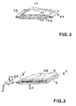
- the metallic foil 20 is inserted between two layers 21, 22, the latter in the edge region 23 merged in parallel and welded together there. This creates a structure that approximates a "mouth bag”.
- Fig. 3 shows schematically a composite body consisting of heat-conducting foil - metal foil - heat-conducting foil.
- 30 shows a spray gun for spraying plastic material onto the edge regions 31, the spraying of the edge regions can either be carried out individually or by placing the three-layer or multi-layer composite bodies of the stack on top of one another and spraying them together.
- the heat-conducting film 2 has a separable section 40, which is formed by perforating the film and serves to expose the otherwise enclosed metallic film.
Landscapes
- Physics & Mathematics (AREA)
- Thermal Sciences (AREA)
- Engineering & Computer Science (AREA)
- Microelectronics & Electronic Packaging (AREA)
- Cooling Or The Like Of Semiconductors Or Solid State Devices (AREA)
Applications Claiming Priority (2)
| Application Number | Priority Date | Filing Date | Title |
|---|---|---|---|
| DE4336961A DE4336961C2 (de) | 1993-10-29 | 1993-10-29 | Flexible Wärmeübertragungsvorrichtung |
| DE4336961 | 1993-10-29 |
Publications (3)
| Publication Number | Publication Date |
|---|---|
| EP0651603A2 true EP0651603A2 (fr) | 1995-05-03 |
| EP0651603A3 EP0651603A3 (fr) | 1995-07-26 |
| EP0651603B1 EP0651603B1 (fr) | 1996-12-11 |
Family
ID=6501332
Family Applications (1)
| Application Number | Title | Priority Date | Filing Date |
|---|---|---|---|
| EP94115102A Expired - Lifetime EP0651603B1 (fr) | 1993-10-29 | 1994-09-24 | Dispositif flexible pour le transfert de chaleur |
Country Status (2)
| Country | Link |
|---|---|
| EP (1) | EP0651603B1 (fr) |
| DE (2) | DE4336961C2 (fr) |
Cited By (6)
| Publication number | Priority date | Publication date | Assignee | Title |
|---|---|---|---|---|
| FR2744873A1 (fr) * | 1996-02-13 | 1997-08-14 | Electrovac | Corps de refroidissement pour composants electriques ou electroniques |
| WO1999014805A1 (fr) * | 1997-09-19 | 1999-03-25 | Advanced Ceramics Corporation | Dispositif flexible d'echange de chaleur et procede associe |
| US6131651A (en) * | 1998-09-16 | 2000-10-17 | Advanced Ceramics Corporation | Flexible heat transfer device and method |
| US6257328B1 (en) * | 1997-10-14 | 2001-07-10 | Matsushita Electric Industrial Co., Ltd. | Thermal conductive unit and thermal connection structure using the same |
| RU2208266C2 (ru) * | 1997-09-19 | 2003-07-10 | Адвансд Серамикс Корпорейшн | Высокогибкое теплопередающее устройство |
| US7995344B2 (en) * | 2007-01-09 | 2011-08-09 | Lockheed Martin Corporation | High performance large tolerance heat sink |
Families Citing this family (5)
| Publication number | Priority date | Publication date | Assignee | Title |
|---|---|---|---|---|
| JP2004265986A (ja) | 2003-02-28 | 2004-09-24 | Citizen Electronics Co Ltd | 高輝度発光素子及びそれを用いた発光装置及び高輝度発光素子の製造方法 |
| DE102004039565A1 (de) * | 2004-08-13 | 2006-02-23 | Kerafol Keramische Folien Gmbh | Mehrlagige Wärmeleitfolie |
| US8405996B2 (en) | 2009-06-30 | 2013-03-26 | General Electric Company | Article including thermal interface element and method of preparation |
| DE102011005669A1 (de) | 2011-03-17 | 2012-09-20 | Robert Bosch Gmbh | Wärmeleitfolie für die Entwärmung und Fixierung elektronischer Bauelemente |
| DE102016209858B4 (de) | 2016-06-06 | 2026-03-19 | Robert Bosch Gmbh | Elektronische Baugruppe, insbesondere für Elektrofahrzeuge oder Hybridfahrzeuge |
Family Cites Families (11)
| Publication number | Priority date | Publication date | Assignee | Title |
|---|---|---|---|---|
| US4471837A (en) * | 1981-12-28 | 1984-09-18 | Aavid Engineering, Inc. | Graphite heat-sink mountings |
| US4574879A (en) * | 1984-02-29 | 1986-03-11 | The Bergquist Company | Mounting pad for solid-state devices |
| DE3409037A1 (de) * | 1984-03-13 | 1985-09-19 | Robert Bosch Gmbh, 7000 Stuttgart | Elektrisches schaltgeraet |
| FR2567324B1 (fr) * | 1984-07-06 | 1986-11-28 | Telemecanique Electrique | Dispositif de montage, pour composant hybride a couche epaisse notamment pour module electronique |
| DE3629565A1 (de) * | 1986-08-30 | 1988-03-03 | Arno W Latzke | Mittel zur applikation von transdermal resorbierbaren wirkstoffen |
| DE3738897A1 (de) * | 1987-11-17 | 1989-05-24 | Standard Elektrik Lorenz Ag | Waermeleitendes verbindungselement fuer elektrische bauelemente |
| GB2214719B (en) * | 1988-01-26 | 1991-07-24 | Gen Electric Co Plc | Housing for electronic device |
| DE3943437A1 (de) * | 1989-04-05 | 1990-10-25 | Ifm Electronic Gmbh | Waermeuebergangsmessgeraet |
| JPH0817105B2 (ja) * | 1989-11-30 | 1996-02-21 | 日本黒鉛工業株式会社 | 縦縞細条形ヒートシールコネクタ部材とその製造法 |
| EP0476164A1 (fr) * | 1990-09-17 | 1992-03-25 | Siemens Aktiengesellschaft | Rondelle isolante avec un bon couplage de chaleur pour des condensateurs refroidis activement |
| DE4118397A1 (de) * | 1991-06-05 | 1992-12-10 | Ant Nachrichtentech | Mit halbleiterbauelementen bestueckte metallkernleiterplatte |
-
1993
- 1993-10-29 DE DE4336961A patent/DE4336961C2/de not_active Expired - Fee Related
-
1994
- 1994-09-24 DE DE59401260T patent/DE59401260D1/de not_active Expired - Fee Related
- 1994-09-24 EP EP94115102A patent/EP0651603B1/fr not_active Expired - Lifetime
Cited By (6)
| Publication number | Priority date | Publication date | Assignee | Title |
|---|---|---|---|---|
| FR2744873A1 (fr) * | 1996-02-13 | 1997-08-14 | Electrovac | Corps de refroidissement pour composants electriques ou electroniques |
| WO1999014805A1 (fr) * | 1997-09-19 | 1999-03-25 | Advanced Ceramics Corporation | Dispositif flexible d'echange de chaleur et procede associe |
| RU2208266C2 (ru) * | 1997-09-19 | 2003-07-10 | Адвансд Серамикс Корпорейшн | Высокогибкое теплопередающее устройство |
| US6257328B1 (en) * | 1997-10-14 | 2001-07-10 | Matsushita Electric Industrial Co., Ltd. | Thermal conductive unit and thermal connection structure using the same |
| US6131651A (en) * | 1998-09-16 | 2000-10-17 | Advanced Ceramics Corporation | Flexible heat transfer device and method |
| US7995344B2 (en) * | 2007-01-09 | 2011-08-09 | Lockheed Martin Corporation | High performance large tolerance heat sink |
Also Published As
| Publication number | Publication date |
|---|---|
| EP0651603B1 (fr) | 1996-12-11 |
| DE59401260D1 (de) | 1997-01-23 |
| DE4336961C2 (de) | 2000-07-06 |
| EP0651603A3 (fr) | 1995-07-26 |
| DE4336961A1 (de) | 1995-05-04 |
Similar Documents
| Publication | Publication Date | Title |
|---|---|---|
| DE60305734T2 (de) | Verkapseltes elektronisches Bauelement und Verfahren zu dessen Herstellung | |
| DE1615957C3 (fr) | ||
| EP0162149B1 (fr) | Condensateur électrique sous forme d'élément pastille | |
| DE68910215T2 (de) | Automatische Bandmontage-Packung hoher Leistung vom Steckerstift-Typ. | |
| DE2314247C3 (de) | Halbleiteranordnung mit einer biegsamen isolierenden Folie | |
| DE1937664C3 (de) | Halbleiterbauelement | |
| EP0651603B1 (fr) | Dispositif flexible pour le transfert de chaleur | |
| DE4235185A1 (de) | Flache leistungsversorgungseinheit | |
| EP1120831A2 (fr) | Composant électronique avec un dispositif de blindage électromagnétique | |
| EP3095307B1 (fr) | Circuit imprimé, montage et procédé de fabrication d'un montage | |
| DE3321320A1 (de) | Schaltungsanordnung | |
| DE4340718A1 (de) | Elektronikkomponente | |
| EP0841668B1 (fr) | Résistance électrique et son procédé de fabrication | |
| DE69325847T2 (de) | Implantierbarer Herz-Defibrillator mit energetisch dissipativem Widerstand | |
| EP0535414A2 (fr) | Dispositif de circuit électronique | |
| DE3930858C2 (de) | Modulaufbau | |
| WO2006034700A1 (fr) | Systeme de capteurs | |
| EP2191483A1 (fr) | Composant électrique multicouche | |
| DE2545672B2 (de) | Mehrschichtkondensator und verfahren zu dessen herstellung | |
| WO1982003723A1 (fr) | Contact electrique, notamment pour circuits imprimes de petits appareils electriques | |
| DE1953678A1 (de) | Schaltungstraeger fuer elektrische Schaltungselemente und -bestandteile,sowie Verfahren zu dessen Herstellung | |
| DE1059988B (de) | Elektrische Baugruppe | |
| DE7933844U1 (de) | Wärmeleitvorrichtung für elektrische Geräte | |
| DE3638858A1 (de) | Elektrolumineszenzvorrichtung | |
| DE102004054996B4 (de) | Elektronisches Gerät |
Legal Events
| Date | Code | Title | Description |
|---|---|---|---|
| PUAI | Public reference made under article 153(3) epc to a published international application that has entered the european phase |
Free format text: ORIGINAL CODE: 0009012 |
|
| AK | Designated contracting states |
Kind code of ref document: A2 Designated state(s): DE FR GB IT |
|
| PUAL | Search report despatched |
Free format text: ORIGINAL CODE: 0009013 |
|
| AK | Designated contracting states |
Kind code of ref document: A3 Designated state(s): DE FR GB IT |
|
| 17P | Request for examination filed |
Effective date: 19950812 |
|
| GRAG | Despatch of communication of intention to grant |
Free format text: ORIGINAL CODE: EPIDOS AGRA |
|
| GRAH | Despatch of communication of intention to grant a patent |
Free format text: ORIGINAL CODE: EPIDOS IGRA |
|
| 17Q | First examination report despatched |
Effective date: 19960422 |
|
| GRAH | Despatch of communication of intention to grant a patent |
Free format text: ORIGINAL CODE: EPIDOS IGRA |
|
| GRAA | (expected) grant |
Free format text: ORIGINAL CODE: 0009210 |
|
| AK | Designated contracting states |
Kind code of ref document: B1 Designated state(s): DE FR GB IT |
|
| REF | Corresponds to: |
Ref document number: 59401260 Country of ref document: DE Date of ref document: 19970123 |
|
| ITF | It: translation for a ep patent filed | ||
| GBT | Gb: translation of ep patent filed (gb section 77(6)(a)/1977) |
Effective date: 19970311 |
|
| ET | Fr: translation filed | ||
| PLBE | No opposition filed within time limit |
Free format text: ORIGINAL CODE: 0009261 |
|
| STAA | Information on the status of an ep patent application or granted ep patent |
Free format text: STATUS: NO OPPOSITION FILED WITHIN TIME LIMIT |
|
| RIN2 | Information on inventor provided after grant (corrected) |
Free format text: KOPPE, FRANZ * HAAS, WERNER |
|
| 26N | No opposition filed | ||
| PGFP | Annual fee paid to national office [announced via postgrant information from national office to epo] |
Ref country code: GB Payment date: 20010830 Year of fee payment: 8 |
|
| PGFP | Annual fee paid to national office [announced via postgrant information from national office to epo] |
Ref country code: FR Payment date: 20010917 Year of fee payment: 8 |
|
| PGFP | Annual fee paid to national office [announced via postgrant information from national office to epo] |
Ref country code: DE Payment date: 20010926 Year of fee payment: 8 |
|
| REG | Reference to a national code |
Ref country code: GB Ref legal event code: IF02 |
|
| PG25 | Lapsed in a contracting state [announced via postgrant information from national office to epo] |
Ref country code: GB Free format text: LAPSE BECAUSE OF NON-PAYMENT OF DUE FEES Effective date: 20020924 |
|
| PG25 | Lapsed in a contracting state [announced via postgrant information from national office to epo] |
Ref country code: DE Free format text: LAPSE BECAUSE OF NON-PAYMENT OF DUE FEES Effective date: 20030401 |
|
| GBPC | Gb: european patent ceased through non-payment of renewal fee |
Effective date: 20020924 |
|
| PG25 | Lapsed in a contracting state [announced via postgrant information from national office to epo] |
Ref country code: FR Free format text: LAPSE BECAUSE OF NON-PAYMENT OF DUE FEES Effective date: 20030603 |
|
| REG | Reference to a national code |
Ref country code: FR Ref legal event code: ST |
|
| PG25 | Lapsed in a contracting state [announced via postgrant information from national office to epo] |
Ref country code: IT Free format text: LAPSE BECAUSE OF NON-PAYMENT OF DUE FEES;WARNING: LAPSES OF ITALIAN PATENTS WITH EFFECTIVE DATE BEFORE 2007 MAY HAVE OCCURRED AT ANY TIME BEFORE 2007. THE CORRECT EFFECTIVE DATE MAY BE DIFFERENT FROM THE ONE RECORDED. Effective date: 20050924 |