EP0651704B2 - Vorrichtung zum steuern von positionen von bewegungsachsen - Google Patents
Vorrichtung zum steuern von positionen von bewegungsachsen Download PDFInfo
- Publication number
- EP0651704B2 EP0651704B2 EP94916270A EP94916270A EP0651704B2 EP 0651704 B2 EP0651704 B2 EP 0651704B2 EP 94916270 A EP94916270 A EP 94916270A EP 94916270 A EP94916270 A EP 94916270A EP 0651704 B2 EP0651704 B2 EP 0651704B2
- Authority
- EP
- European Patent Office
- Prior art keywords
- motor
- sensor
- position sensor
- shaft
- hall
- Prior art date
- Legal status (The legal status is an assumption and is not a legal conclusion. Google has not performed a legal analysis and makes no representation as to the accuracy of the status listed.)
- Expired - Lifetime
Links
Images


Classifications
-
- B—PERFORMING OPERATIONS; TRANSPORTING
- B60—VEHICLES IN GENERAL
- B60N—SEATS SPECIALLY ADAPTED FOR VEHICLES; VEHICLE PASSENGER ACCOMMODATION NOT OTHERWISE PROVIDED FOR
- B60N2/00—Seats specially adapted for vehicles; Arrangement or mounting of seats in vehicles
- B60N2/02—Seats specially adapted for vehicles; Arrangement or mounting of seats in vehicles the seat or part thereof being movable, e.g. adjustable
- B60N2/0224—Non-manual adjustments, e.g. with electrical operation
- B60N2/0244—Non-manual adjustments, e.g. with electrical operation with logic circuits
- B60N2/0248—Non-manual adjustments, e.g. with electrical operation with logic circuits with memory of positions
-
- B—PERFORMING OPERATIONS; TRANSPORTING
- B60—VEHICLES IN GENERAL
- B60N—SEATS SPECIALLY ADAPTED FOR VEHICLES; VEHICLE PASSENGER ACCOMMODATION NOT OTHERWISE PROVIDED FOR
- B60N2/00—Seats specially adapted for vehicles; Arrangement or mounting of seats in vehicles
- B60N2/02—Seats specially adapted for vehicles; Arrangement or mounting of seats in vehicles the seat or part thereof being movable, e.g. adjustable
- B60N2/0224—Non-manual adjustments, e.g. with electrical operation
-
- B—PERFORMING OPERATIONS; TRANSPORTING
- B60—VEHICLES IN GENERAL
- B60N—SEATS SPECIALLY ADAPTED FOR VEHICLES; VEHICLE PASSENGER ACCOMMODATION NOT OTHERWISE PROVIDED FOR
- B60N2/00—Seats specially adapted for vehicles; Arrangement or mounting of seats in vehicles
- B60N2/02—Seats specially adapted for vehicles; Arrangement or mounting of seats in vehicles the seat or part thereof being movable, e.g. adjustable
- B60N2/0224—Non-manual adjustments, e.g. with electrical operation
- B60N2/0244—Non-manual adjustments, e.g. with electrical operation with logic circuits
- B60N2/0272—Non-manual adjustments, e.g. with electrical operation with logic circuits using sensors or detectors for detecting the position of seat parts
-
- G—PHYSICS
- G05—CONTROLLING; REGULATING
- G05B—CONTROL OR REGULATING SYSTEMS IN GENERAL; FUNCTIONAL ELEMENTS OF SUCH SYSTEMS; MONITORING OR TESTING ARRANGEMENTS FOR SUCH SYSTEMS OR ELEMENTS
- G05B19/00—Program-control systems
- G05B19/02—Program-control systems electric
- G05B19/18—Numerical control [NC], i.e. automatically operating machines, in particular machine tools, e.g. in a manufacturing environment, so as to execute positioning, movement or co-ordinated operations by means of program data in numerical form
- G05B19/414—Structure of the control system, e.g. common controller or multiprocessor systems, interface to servo, programmable interface controller
- G05B19/4142—Structure of the control system, e.g. common controller or multiprocessor systems, interface to servo, programmable interface controller characterised by the use of a microprocessor
-
- B—PERFORMING OPERATIONS; TRANSPORTING
- B60—VEHICLES IN GENERAL
- B60N—SEATS SPECIALLY ADAPTED FOR VEHICLES; VEHICLE PASSENGER ACCOMMODATION NOT OTHERWISE PROVIDED FOR
- B60N2210/00—Sensor types, e.g. for passenger detection systems or for controlling seats
- B60N2210/10—Field detection presence sensors
- B60N2210/14—Inductive; Magnetic field
-
- G—PHYSICS
- G05—CONTROLLING; REGULATING
- G05B—CONTROL OR REGULATING SYSTEMS IN GENERAL; FUNCTIONAL ELEMENTS OF SUCH SYSTEMS; MONITORING OR TESTING ARRANGEMENTS FOR SUCH SYSTEMS OR ELEMENTS
- G05B2219/00—Program-control systems
- G05B2219/30—Nc systems
- G05B2219/34—Director, elements to supervisory
- G05B2219/34435—Position encoder and motor connection in one interface between motor and microprocessor
-
- G—PHYSICS
- G05—CONTROLLING; REGULATING
- G05B—CONTROL OR REGULATING SYSTEMS IN GENERAL; FUNCTIONAL ELEMENTS OF SUCH SYSTEMS; MONITORING OR TESTING ARRANGEMENTS FOR SUCH SYSTEMS OR ELEMENTS
- G05B2219/00—Program-control systems
- G05B2219/30—Nc systems
- G05B2219/37—Measurements
- G05B2219/37172—Encoder with hall effect and reed relays, and decoder gives absolute position
-
- G—PHYSICS
- G05—CONTROLLING; REGULATING
- G05B—CONTROL OR REGULATING SYSTEMS IN GENERAL; FUNCTIONAL ELEMENTS OF SUCH SYSTEMS; MONITORING OR TESTING ARRANGEMENTS FOR SUCH SYSTEMS OR ELEMENTS
- G05B2219/00—Program-control systems
- G05B2219/30—Nc systems
- G05B2219/45—Nc applications
- G05B2219/45022—Auto seat, dentist chair, roll wheel chair
Definitions
- the present invention relates in a way general a device for controlling axis positions and more particularly a device control of the axes of movement of a vehicle seat with electronic functions such as that memorizing the positions of the axes of displacement.
- the front seats of a vehicle are adjustable in several directions.
- vehicle seat is meant as well the actual seat or seat on which sits the driver or passenger, as the backrest.
- the seat and backrest are adjustable, independently from each other, in several directions. Every displacement or movement of the seat are associated with drive motor and a position sensor, these the latter being controlled by electronics which is able for example to memorize the various positions of the seat, so as to allow the user, by a simple command key, to recall the seat to a predetermined position previously stored.
- the first position sensor killer is electromechanical and includes either a wiper or a potentiometer, the position of the axis of movement being identified, in the case of the potentiometer, by the resistive value of the latter, using a slider which is connected to the motor and which constitutes the movable element.
- a second type of position sensor can be optical, with an infrared transceiver, the element mobile and connecting with the motor being constituted by a gear.
- a third type of position sensor uses a flexible reed switch, moving element and bond then being a multipolar magnet.
- a fourth type of position sensor is Hall effect with, as a movable and connecting element, a multipolar magnet.
- a first solution is to mount the sensor on a reduction gear which is connected to the motor by a core metallic, generally of square section and arranged in a sheath, the reducer outlet axis constitutes an axis of movement of the seat in a given position and which is memorized by appropriate electronics ; the metal sheath and core assembly constitute what's called a flexible.
- a end of the shaft at the output of the gearbox for the drive of the multipolar magnet of the sensor is to mount the sensor on a reduction gear which is connected to the motor by a core metallic, generally of square section and arranged in a sheath, the reducer outlet axis constitutes an axis of movement of the seat in a given position and which is memorized by appropriate electronics ; the metal sheath and core assembly constitute what's called a flexible.
- a second solution is to mount the sensor at the end of the motor housing opposite to that receiving the hose which connects said motor to the reduction gear.
- a shaft end is provided for ensure the connection of the sensor magnet with the motor.
- a magnet necessarily having a large number of pairs of poles, necessary for detection with good seat position precision, a piece of shaft for magnet training, and at least two sets of connections between control and storage electronics and the position sensor on the one hand, and the motor on the other hand.
- the position sensor is an optical sensor which is mounted on and traversed by a control rod of the engine
- the preamble of claim 1 is referring to this patent.
- said interconnection box constituting a interface between the motor and the control circuit, which characteristic is the subject of the characterizing part of claim 1.
- the object of the present invention is to remedy the disadvantages mentioned above and to propose a device for position control and detection which is very compact therefore occupying less space, requiring fewer electrical connections, thereby increasing reliability of the system.
- the present invention relates to a device for position control of at least one axis of movement, as defined in claim 1.
- An advantage of the present invention lies in the fact that all electrical and mechanical connections are carried out through and through a electrical and mechanical interface.
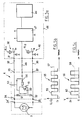
- the device according to the invention comprises a housing interconnection 1 which is shown in Figures 1 to 3 and which has the particularity of constituting an interface between a drive motor known per se, and a control circuit which is shown schematically in Figures 4 and 5. Therefore, it is no longer necessary to provide a specific connector to realize the various connections between the control circuit, the motor and the position sensor which is arranged in the housing 1, said connections now being made directly through box 1 and in some case through the position sensor, like this is described below.
- the housing 1 is mounted at one end 2 of a motor 3, the fixing being effected by any means suitable, such as screws or bolts fitting into ears 4 and screwing into tapped bores or not, arranged in the motor housing.
- a flexible 5 comprising a sheath 6 and an internal metallic core or drive rod 7, of square section at ends for example, connects motor 3 to a gearbox speed integral with the seat drive axis, not shown.
- the hose 5 has a nozzle 8 which is housed and fixed, for example by clipping into a housing 9 formed in the base 10 of the housing 1 ( Figure 3).
- the core 7 passes completely through the shoemaker 1, its end 11 being connected to the motor drive shaft 3, of usual way, such a connection being schematically materialized by the reference 12.
- the cover 14 is made integral with the base 10 by means of a flexible clip tab 15 which comes to bear on a support and blocking rim 16 formed on one side of said base 10.
- the position sensor which is of the Hall effect type includes a receiver 19 and an information generator 25 representative of displacement and / or position of the axis of displacement A, which can be consisting, for example, of a screw of a moving a seat.
- a printed circuit 18 on which the receiver is fixed Hall effect 19, the printed circuit 18 being provided with passages 20 for mounting and fixing connection 21 (figure 3).
- An envelope 22 provided with a positioning tip and fixing 23, is mounted on an area of reception 24 of the base 10.
- the envelope 22 constitutes protection for the Hall 19 receiver and a housing for the generator 25 which is constituted by a magnet associated with said Hall effect receiver 19, a guide ring 26 for the magnet also being planned.
- the magnet 25 includes only a pair of poles and it is driven by motor 3, through of the inner core 7 of the hose 5 and of the ring 26 which is provided with a hole 27 with a square section.
- Use a magnet 25 with two poles, a North and a South makes it easier and less expensive cost, in particular by the fact that the northern and South are easier to achieve, the rotation speed high of said magnet imposed by the motor 3 ensuring good seat positioning accuracy.
- the Hall effect position sensor used can be of the unipolar or bipolar type, whereas in the previous solutions, only an effect position sensor Bipolar hall could be used with a large magnet number of poles.
- the receiver 19 can be positioned at a relative greater distance from the magnet (25), which allows, as in the case shown in the figures, to place it under the envelope 22, the latter thus constituting protection for the receiver 19.
- the control circuit 29, in a first mode shown in Figure 4, control the motor 3 through the housing 1 which thus serves as a connector or connection interface between said circuit control and motor.
- the motor supply by example from the vehicle battery, is performed by a power supply sub-assembly 30 whose connector output is schematically represented and designated by the reference 31.
- a conductor 32 connects the connector 31 to connector 33 and to the tab of corresponding connection 34 which is plugged into a receptacle or any other connecting member of the motor 3 and designated schematically by the reference 34 '.
- the return to earth of the motor is carried out by through the other connection tab 35 of the interconnection box 1, connector 37, conductor 38, a connector 39 and a sub-assembly 40. Links 32, 38, 41, 42, 43 can also be crimped or welded to the housing 1.
- the receiver 19 is supplied from a 5V supply, from the control circuit 29 and a conductor or other connecting member 41, the return to ground being ensured by the conductor 42.
- the signal delivered by the receiver 19 passes through a resistance R of low value, for example 500, compared to that of R 1 which is a few k.
- Resistor R limits the current in receiver 19 in the event of an accidental short circuit of the sensor signal.
- a conductor 43 connects the resistor R to a microprocessor 44 through the sub-assembly 45 comprising in particular the resistors R 1 and R 2 .
- the control circuit 46 is improved with respect to the control circuit 29 in FIG. 4, by the fact that the supply conductors of the receiver 19 are eliminated.
- a current-voltage converter 47 receives two 12V and 5V supplies, the 12V supply being intended to supply the receiver 19 through a low value shunt (not shown) and via a conductor 48 connected between the circuit 46 and the housing 1.
- the elements which are identical to the embodiment shown in Figure 4 are designated by the same references.
- the supply voltage is applied to the Hall sensor 19.25, the latter being returned to ground.
- the transistor 50 When the transistor 50 is not on, that is to say when the north pole of the magnet 25 is facing the receiver 19, the supply voltage passes through the branch 53in which a current l 1 constantly flows . Each time the south pole of the magnet 25 faces the receiver 19, a current l 2 flows in the branch 54 through the resistor R.
- the curves 55 and 56 respectively represent the signals delivered by the receiver 19 and received on the microprocessor 44, as a function of time. In both cases, a current detection threshold 57 and a voltage detection threshold 58 are provided.
- a pulse 59 delivered by the receiver 19 and of value l l 1 + l 2 corresponds to a pulse 60 delivered by the converter 47 to the microprocessor 44.
- the microprocessor 44 counts and stores the pulses 60.
- the microprocessor comparator 44 compares N 2 with N 1 . Depending on whether N 2 is larger or smaller than N 1 , the microprocessor 44 then controls the rotation of the motor 3 in one direction or the other, so that the axis of movement, driven by the motor and associated with said seat part, be brought into the desired position.
- Block 61 represents, for example, a grouping of three engines, the block 62 representing a mechanical connection box and electric comprising three position sensors.
- a flexible hose is associated with each position sensor whose internal core controls the movement of an axis displacement, references 63 to 65 designating the flexible and references 66 to 68 designating the axes of displacement.
- a bundle 69 of conductors is connected in block 62. The number of these conductors may be variable according to the principle of grouping of connections that will be retained.
- the assembly constituted by the Hall effect sensor with its electrical connections between motor and circuit is housed in the interconnection box, which interconnect box is directly mounted to the end of the motor controlling one or more vehicle seat mechanisms.
Landscapes
- Engineering & Computer Science (AREA)
- Aviation & Aerospace Engineering (AREA)
- Transportation (AREA)
- Mechanical Engineering (AREA)
- Computer Hardware Design (AREA)
- Microelectronics & Electronic Packaging (AREA)
- Human Computer Interaction (AREA)
- Manufacturing & Machinery (AREA)
- Physics & Mathematics (AREA)
- General Physics & Mathematics (AREA)
- Automation & Control Theory (AREA)
- Seats For Vehicles (AREA)
- Connection Of Motors, Electrical Generators, Mechanical Devices, And The Like (AREA)
- Control Of Position Or Direction (AREA)
Claims (7)
- Vorrichtung zur Positionssteuerung von wenigstens einer Verstellachse (A) eines Fahrzeugsitzmechanismus, vom Typ mit einem Antriebsmotor (3), einer Antriebsstange (7), die mit dem Motor verbunden und zwischen dem Antriebsmotor (3) und der Verstellachse angeordnet ist, einem Steuerkreis (29, 46) des Motors (3) und einem Positionsgeber mit einem Empfänger (19) und einem Informationsgenerator (25) zur Erzeugung einer Information, die für die Verstellung und/oder die Position der Verstellachse charakteristisch ist, wobei der Positionsgeber (19, 25) nahe dem Motor und auf der Seite eines Endes der Antriebsstange angeordnet ist, und der Generator (15) auf der Antriebsstange (7) angeordnet und von dieser angetrieben ist,
dadurch gekennzeichnet, daß
der Positionsgeber (19, 25) und die elektrischen Verbindungen zwischen dem Motor, dem Geber und dem Steuerkreis in einem Verbindungsgehäuse (1) angeordnet sind, das ein Interface zwischen dem Motor und den Steuerkreisen (29, 46) bildet, so daß die Achse des Motors (3), das Gehäuse (1) und die Verstellachse (A) fluchten, und daß die Antriebsstange (7) derart in einer Hülle (6) angeordnet ist, daß ein flexibler Schlauch (5) gebildet wird. - Vorrichtung nach Anspruch 1,
dadurch gekennzeichnet, daß
der Positionsgeber (19, 25) mit Hall-Effekt ausgebildet ist, dessen Generator von einem Magneten (25) mit wenigstens zwei Polen gebildet ist. - Vorrichtung nach Anspruch 2,
dadurch gekennzeichnet, daß
eine Schutzhülle (22) zwischen dem Magneten (25) und dem Empfänger (19) angeordnet ist. - Vorrichtung nach Anspruch 1 oder 2,
dadurch gekennzeichnet, daß
sie außerdem zwei Dioden (51, 51) aufweist, die gegensinnig an Speise- und Masserückleitungen (34, 36) des Motors angeschlossen sind, und daß die Versorgung des Positionsgebers mittels eines Signalleiters des Halleffektgebers erfolgt. - Vorrichtung nach Anspruch 4
dadurch gekennzeichnet, daß
der Speise- und Signalleiter des Halleffektgebers an einen Strom/Spannungswandler (47) angeschlossen ist, der die Impulse des Halleffektgebers an einen Mikroprozessor abgibt, der die vom Strom/Spannungswandler abgegebenen Impulse insbesondere zählt und speichert. - Vorrichtung nach Anspruch 1,
dadurch gekennzeichnet, daß
die Anzahl der Leiter zwischen dem Steuerkreis und dem Interface auf nur drei (32, 48, 38) begrenzt ist. - Vorrichtung nach Anspruch 1,
dadurch gekennzeichnet, daß
ein einziges Verbindungsgehäuse (62) mehreren Verstellachsen eines Fahrzeugsitzes zugeordnet ist.
Applications Claiming Priority (3)
| Application Number | Priority Date | Filing Date | Title |
|---|---|---|---|
| FR9305999 | 1993-05-18 | ||
| FR9305999A FR2705473B1 (fr) | 1993-05-18 | 1993-05-18 | Dispositif de commande de positions d'axes de déplacement. |
| PCT/FR1994/000560 WO1994026552A1 (fr) | 1993-05-18 | 1994-05-11 | Dispositif de commande de positions d'axes de deplacement |
Publications (3)
| Publication Number | Publication Date |
|---|---|
| EP0651704A1 EP0651704A1 (de) | 1995-05-10 |
| EP0651704B1 EP0651704B1 (de) | 1996-12-11 |
| EP0651704B2 true EP0651704B2 (de) | 2000-08-23 |
Family
ID=9447259
Family Applications (1)
| Application Number | Title | Priority Date | Filing Date |
|---|---|---|---|
| EP94916270A Expired - Lifetime EP0651704B2 (de) | 1993-05-18 | 1994-05-11 | Vorrichtung zum steuern von positionen von bewegungsachsen |
Country Status (6)
| Country | Link |
|---|---|
| EP (1) | EP0651704B2 (de) |
| JP (1) | JPH08502227A (de) |
| DE (1) | DE69401116T3 (de) |
| ES (1) | ES2097654T3 (de) |
| FR (1) | FR2705473B1 (de) |
| WO (1) | WO1994026552A1 (de) |
Families Citing this family (3)
| Publication number | Priority date | Publication date | Assignee | Title |
|---|---|---|---|---|
| US6339302B1 (en) * | 1998-12-15 | 2002-01-15 | Prince Technology Corporation | Vehicle control system |
| DE20014700U1 (de) | 2000-08-25 | 2001-02-15 | Brose Fahrzeugteile GmbH & Co. KG, Coburg, 96450 Coburg | Vorrichtung zum Erfassen und Übertragung von mindestens einer Kenngröße und einer Richtung einer Bewegung zu zueinander beweglichen Teilen, insbesondere für Sitzverstellantriebe in Kraftfahrzeugen |
| DE10229369B4 (de) * | 2001-07-10 | 2006-09-21 | Keiper Gmbh & Co.Kg | Sensor für einen Fahrzeugsitz |
Citations (4)
| Publication number | Priority date | Publication date | Assignee | Title |
|---|---|---|---|---|
| US4473786A (en) † | 1981-03-04 | 1984-09-25 | Hitachi, Ltd. | Method for controlling angular position and apparatus therefor |
| DE3034188C2 (de) † | 1980-09-11 | 1987-12-10 | Ernst Koch & Co, 5870 Hemer, De | |
| EP0335352A2 (de) † | 1988-03-31 | 1989-10-04 | SCHUNK Motorensysteme GmbH | Becherförmiger Träger bestimmt für einen Elektromotor |
| EP0474904A1 (de) † | 1990-09-12 | 1992-03-18 | Siemens Aktiengesellschaft | Kommutator-Getriebe-Antriebseinheit, insbesondere Fensterheberantrieb für ein Kraftfahrzeug, und Verfahren zu deren Herstellung |
Family Cites Families (5)
| Publication number | Priority date | Publication date | Assignee | Title |
|---|---|---|---|---|
| JPS5630284Y2 (de) * | 1978-10-09 | 1981-07-18 | ||
| JPS56138024A (en) * | 1980-03-31 | 1981-10-28 | Aisin Seiki Co Ltd | Driver's seat |
| US4907153A (en) * | 1987-08-24 | 1990-03-06 | Brodsky Stephen L | Automobile seat position control system |
| JPH083162Y2 (ja) * | 1988-07-08 | 1996-01-29 | 松下電器産業株式会社 | センサ付ウォームギヤモータ |
| FR2660259B1 (fr) * | 1990-03-27 | 1992-07-24 | Rockwell Cim | Dispositif de commande motorisee d'un ensemble d'elements tels que les parties reglables d'un siege de vehicule. |
-
1993
- 1993-05-18 FR FR9305999A patent/FR2705473B1/fr not_active Expired - Lifetime
-
1994
- 1994-05-11 WO PCT/FR1994/000560 patent/WO1994026552A1/fr not_active Ceased
- 1994-05-11 DE DE69401116T patent/DE69401116T3/de not_active Expired - Fee Related
- 1994-05-11 EP EP94916270A patent/EP0651704B2/de not_active Expired - Lifetime
- 1994-05-11 JP JP6525066A patent/JPH08502227A/ja active Pending
- 1994-05-11 ES ES94916270T patent/ES2097654T3/es not_active Expired - Lifetime
Patent Citations (4)
| Publication number | Priority date | Publication date | Assignee | Title |
|---|---|---|---|---|
| DE3034188C2 (de) † | 1980-09-11 | 1987-12-10 | Ernst Koch & Co, 5870 Hemer, De | |
| US4473786A (en) † | 1981-03-04 | 1984-09-25 | Hitachi, Ltd. | Method for controlling angular position and apparatus therefor |
| EP0335352A2 (de) † | 1988-03-31 | 1989-10-04 | SCHUNK Motorensysteme GmbH | Becherförmiger Träger bestimmt für einen Elektromotor |
| EP0474904A1 (de) † | 1990-09-12 | 1992-03-18 | Siemens Aktiengesellschaft | Kommutator-Getriebe-Antriebseinheit, insbesondere Fensterheberantrieb für ein Kraftfahrzeug, und Verfahren zu deren Herstellung |
Also Published As
| Publication number | Publication date |
|---|---|
| EP0651704B1 (de) | 1996-12-11 |
| DE69401116D1 (de) | 1997-01-23 |
| ES2097654T3 (es) | 1997-04-01 |
| FR2705473A1 (fr) | 1994-11-25 |
| WO1994026552A1 (fr) | 1994-11-24 |
| DE69401116T2 (de) | 1997-07-10 |
| DE69401116T3 (de) | 2001-03-15 |
| FR2705473B1 (fr) | 1995-07-21 |
| EP0651704A1 (de) | 1995-05-10 |
| JPH08502227A (ja) | 1996-03-12 |
Similar Documents
| Publication | Publication Date | Title |
|---|---|---|
| WO2015033033A1 (fr) | Interface de commande à retour haptique | |
| FR2663798A1 (fr) | Dispositif d'entrainement electromoteur, notamment comme organe de reglage de fenetre a commande electrique ou de toits coulissants de vehicules. | |
| EP0449688B1 (de) | Motorgetriebene Vorrichtung zur Verstellung eines Satzes von Elementen, insbesondere der verstellbaren Teile eines Fahrzeugsitzes | |
| FR2734425A1 (fr) | Alternateur, notamment pour vehicule automobile, comportant un agencement perfectionne de diodes de redressement | |
| EP0651704B1 (de) | Vorrichtung zum steuern von positionen von bewegungsachsen | |
| FR2594758A1 (fr) | Embrayage, notamment pour vehicules automobiles | |
| FR2664212A1 (fr) | Motoreducteur d'entrainement de pieces telles que des accessoires de vehicules automobiles, notamment un toit ouvrant. | |
| EP0371851A1 (de) | Hilfseinrichtung zur Behandlung der Schwächen eines elektrischen linearen Windenantriebssystems | |
| FR2859050A1 (fr) | Unite d'entrainement et de transmission comportant au moins deux moteurs pour actionner ou deplacer une piece equipant un vehicule automobile | |
| EP0943508A1 (de) | Fahrzeugdiebstahlsicherung mit zusammenarbeitendem Zündschloss | |
| EP1555463B1 (de) | Getriebesteuerungseinrichtung, insbesondere für Fahrzeuge | |
| FR3099433A3 (fr) | Système amélioré de maintien pour un véhicule de travail | |
| EP0466539A1 (de) | Steuerungseinrichtung zur Neigung eines Fahrzeugscheinwerfers | |
| EP0367668B1 (de) | Positionssteuereinrichtung zur Lageregelung eines beweglichen Organs in verschiedene diskrete Stellungen, speziell für die Neigung von Automobilscheinwerfern | |
| FR2760546A1 (fr) | Dispositif d'asservissement d'un levier de commande d'une boite de vitesses mecanique pour vehicule automobile | |
| FR2784061A1 (fr) | Transmission comportant un capteur a effet hall | |
| FR2836974A1 (fr) | Dispositif electronique et procede de selection de vitesses pour boite de vitesses automatiques | |
| FR2776858A1 (fr) | Dispositif de maintien, de positionnement, ou de serrage, a actionnement electrique | |
| EP0219411B1 (de) | Getriebemotor für den gleichzeitigen Antrieb zweier Organe | |
| EP0186596B1 (de) | Regelsystem zur linearen Verschiebung mit einem Gleichstrommotor | |
| FR2738586A1 (fr) | Cle a contact et dispositif de verrouillage a cle et serrure l'incorporant, notamment pour vehicule automobile | |
| FR2486230A1 (fr) | Perfectionnements a un dispositif tachymetrique commande par un moteur electrique | |
| FR2596722A1 (fr) | Direction assistee pour vehicules automobiles | |
| FR2530030A1 (fr) | Dispositif tachymetrique commande electroniquement | |
| EP3211489B1 (de) | Vereinfachtes motormodul |
Legal Events
| Date | Code | Title | Description |
|---|---|---|---|
| PUAI | Public reference made under article 153(3) epc to a published international application that has entered the european phase |
Free format text: ORIGINAL CODE: 0009012 |
|
| 17P | Request for examination filed |
Effective date: 19941109 |
|
| AK | Designated contracting states |
Kind code of ref document: A1 Designated state(s): DE ES FR GB IT |
|
| GRAG | Despatch of communication of intention to grant |
Free format text: ORIGINAL CODE: EPIDOS AGRA |
|
| GRAH | Despatch of communication of intention to grant a patent |
Free format text: ORIGINAL CODE: EPIDOS IGRA |
|
| 17Q | First examination report despatched |
Effective date: 19960506 |
|
| GRAH | Despatch of communication of intention to grant a patent |
Free format text: ORIGINAL CODE: EPIDOS IGRA |
|
| GRAA | (expected) grant |
Free format text: ORIGINAL CODE: 0009210 |
|
| AK | Designated contracting states |
Kind code of ref document: B1 Designated state(s): DE ES FR GB IT |
|
| REF | Corresponds to: |
Ref document number: 69401116 Country of ref document: DE Date of ref document: 19970123 |
|
| GBT | Gb: translation of ep patent filed (gb section 77(6)(a)/1977) |
Effective date: 19970125 |
|
| ITF | It: translation for a ep patent filed | ||
| REG | Reference to a national code |
Ref country code: ES Ref legal event code: FG2A Ref document number: 2097654 Country of ref document: ES Kind code of ref document: T3 |
|
| PLBQ | Unpublished change to opponent data |
Free format text: ORIGINAL CODE: EPIDOS OPPO |
|
| PLBQ | Unpublished change to opponent data |
Free format text: ORIGINAL CODE: EPIDOS OPPO |
|
| PLBI | Opposition filed |
Free format text: ORIGINAL CODE: 0009260 |
|
| PLBF | Reply of patent proprietor to notice(s) of opposition |
Free format text: ORIGINAL CODE: EPIDOS OBSO |
|
| 26 | Opposition filed |
Opponent name: LEOPOLD KOSTAL GMBH & CO. KG Effective date: 19970910 Opponent name: BROSE FAHRZEUGTEILE GMBH & CO. KG Effective date: 19970911 |
|
| PLBF | Reply of patent proprietor to notice(s) of opposition |
Free format text: ORIGINAL CODE: EPIDOS OBSO |
|
| PLBF | Reply of patent proprietor to notice(s) of opposition |
Free format text: ORIGINAL CODE: EPIDOS OBSO |
|
| RAP2 | Party data changed (patent owner data changed or rights of a patent transferred) |
Owner name: BERTRAND FAURE EQUIPEMENTS S.A. Owner name: DAV |
|
| PGFP | Annual fee paid to national office [announced via postgrant information from national office to epo] |
Ref country code: GB Payment date: 19990504 Year of fee payment: 6 |
|
| PGFP | Annual fee paid to national office [announced via postgrant information from national office to epo] |
Ref country code: ES Payment date: 19990521 Year of fee payment: 6 |
|
| PLAW | Interlocutory decision in opposition |
Free format text: ORIGINAL CODE: EPIDOS IDOP |
|
| PLAW | Interlocutory decision in opposition |
Free format text: ORIGINAL CODE: EPIDOS IDOP |
|
| PG25 | Lapsed in a contracting state [announced via postgrant information from national office to epo] |
Ref country code: GB Free format text: LAPSE BECAUSE OF NON-PAYMENT OF DUE FEES Effective date: 20000511 |
|
| PG25 | Lapsed in a contracting state [announced via postgrant information from national office to epo] |
Ref country code: ES Free format text: THE PATENT HAS BEEN ANNULLED BY A DECISION OF A NATIONAL AUTHORITY Effective date: 20000512 |
|
| PGFP | Annual fee paid to national office [announced via postgrant information from national office to epo] |
Ref country code: FR Payment date: 20000530 Year of fee payment: 7 |
|
| PGFP | Annual fee paid to national office [announced via postgrant information from national office to epo] |
Ref country code: DE Payment date: 20000629 Year of fee payment: 7 |
|
| PUAH | Patent maintained in amended form |
Free format text: ORIGINAL CODE: 0009272 |
|
| STAA | Information on the status of an ep patent application or granted ep patent |
Free format text: STATUS: PATENT MAINTAINED AS AMENDED |
|
| 27A | Patent maintained in amended form |
Effective date: 20000823 |
|
| AK | Designated contracting states |
Kind code of ref document: B2 Designated state(s): DE ES FR GB IT |
|
| ITF | It: translation for a ep patent filed | ||
| GBPC | Gb: european patent ceased through non-payment of renewal fee |
Effective date: 20000511 |
|
| PG25 | Lapsed in a contracting state [announced via postgrant information from national office to epo] |
Ref country code: FR Free format text: LAPSE BECAUSE OF NON-PAYMENT OF DUE FEES Effective date: 20020131 |
|
| PG25 | Lapsed in a contracting state [announced via postgrant information from national office to epo] |
Ref country code: DE Free format text: LAPSE BECAUSE OF NON-PAYMENT OF DUE FEES Effective date: 20020301 |
|
| REG | Reference to a national code |
Ref country code: ES Ref legal event code: FD2A Effective date: 20020204 |
|
| PG25 | Lapsed in a contracting state [announced via postgrant information from national office to epo] |
Ref country code: IT Free format text: LAPSE BECAUSE OF NON-PAYMENT OF DUE FEES Effective date: 20050511 |