EP0651925B1 - Systemes de communication en diversite dans le temps a saut de frequence - Google Patents
Systemes de communication en diversite dans le temps a saut de frequence Download PDFInfo
- Publication number
- EP0651925B1 EP0651925B1 EP93918322A EP93918322A EP0651925B1 EP 0651925 B1 EP0651925 B1 EP 0651925B1 EP 93918322 A EP93918322 A EP 93918322A EP 93918322 A EP93918322 A EP 93918322A EP 0651925 B1 EP0651925 B1 EP 0651925B1
- Authority
- EP
- European Patent Office
- Prior art keywords
- bit
- brcnt
- receiver
- packet
- rate
- Prior art date
- Legal status (The legal status is an assumption and is not a legal conclusion. Google has not performed a legal analysis and makes no representation as to the accuracy of the status listed.)
- Expired - Lifetime
Links
Images













Classifications
-
- H—ELECTRICITY
- H04—ELECTRIC COMMUNICATION TECHNIQUE
- H04J—MULTIPLEX COMMUNICATION
- H04J13/00—Code division multiplex systems
-
- G—PHYSICS
- G05—CONTROLLING; REGULATING
- G05D—SYSTEMS FOR CONTROLLING OR REGULATING NON-ELECTRIC VARIABLES
- G05D1/00—Control of position, course, altitude or attitude of land, water, air or space vehicles, e.g. using automatic pilots
- G05D1/02—Control of position or course in two dimensions
- G05D1/021—Control of position or course in two dimensions specially adapted to land vehicles
- G05D1/0259—Control of position or course in two dimensions specially adapted to land vehicles using magnetic or electromagnetic means
- G05D1/0265—Control of position or course in two dimensions specially adapted to land vehicles using magnetic or electromagnetic means using buried wires
-
- H—ELECTRICITY
- H03—ELECTRONIC CIRCUITRY
- H03G—CONTROL OF AMPLIFICATION
- H03G3/00—Gain control in amplifiers or frequency changers
- H03G3/001—Digital control of analog signals
-
- H—ELECTRICITY
- H03—ELECTRONIC CIRCUITRY
- H03G—CONTROL OF AMPLIFICATION
- H03G3/00—Gain control in amplifiers or frequency changers
- H03G3/002—Control of digital or coded signals
-
- H—ELECTRICITY
- H04—ELECTRIC COMMUNICATION TECHNIQUE
- H04B—TRANSMISSION
- H04B1/00—Details of transmission systems, not covered by a single one of groups H04B3/00 - H04B13/00; Details of transmission systems not characterised by the medium used for transmission
- H04B1/69—Spread spectrum techniques
-
- H—ELECTRICITY
- H04—ELECTRIC COMMUNICATION TECHNIQUE
- H04B—TRANSMISSION
- H04B1/00—Details of transmission systems, not covered by a single one of groups H04B3/00 - H04B13/00; Details of transmission systems not characterised by the medium used for transmission
- H04B1/69—Spread spectrum techniques
- H04B1/713—Spread spectrum techniques using frequency hopping
-
- H—ELECTRICITY
- H04—ELECTRIC COMMUNICATION TECHNIQUE
- H04B—TRANSMISSION
- H04B1/00—Details of transmission systems, not covered by a single one of groups H04B3/00 - H04B13/00; Details of transmission systems not characterised by the medium used for transmission
- H04B1/69—Spread spectrum techniques
- H04B1/713—Spread spectrum techniques using frequency hopping
- H04B1/715—Interference-related aspects
-
- H—ELECTRICITY
- H04—ELECTRIC COMMUNICATION TECHNIQUE
- H04B—TRANSMISSION
- H04B3/00—Line transmission systems
- H04B3/54—Systems for transmission via power distribution lines
-
- H—ELECTRICITY
- H04—ELECTRIC COMMUNICATION TECHNIQUE
- H04B—TRANSMISSION
- H04B3/00—Line transmission systems
- H04B3/54—Systems for transmission via power distribution lines
- H04B3/56—Circuits for coupling, blocking, or by-passing of signals
-
- H—ELECTRICITY
- H04—ELECTRIC COMMUNICATION TECHNIQUE
- H04B—TRANSMISSION
- H04B7/00—Radio transmission systems, i.e. using radiation field
- H04B7/02—Diversity systems; Multi-antenna system, i.e. transmission or reception using multiple antennas
- H04B7/04—Diversity systems; Multi-antenna system, i.e. transmission or reception using multiple antennas using two or more spaced independent antennas
- H04B7/06—Diversity systems; Multi-antenna system, i.e. transmission or reception using multiple antennas using two or more spaced independent antennas at the transmitting station
- H04B7/0613—Diversity systems; Multi-antenna system, i.e. transmission or reception using multiple antennas using two or more spaced independent antennas at the transmitting station using simultaneous transmission
- H04B7/0667—Diversity systems; Multi-antenna system, i.e. transmission or reception using multiple antennas using two or more spaced independent antennas at the transmitting station using simultaneous transmission of delayed versions of same signal
- H04B7/0671—Diversity systems; Multi-antenna system, i.e. transmission or reception using multiple antennas using two or more spaced independent antennas at the transmitting station using simultaneous transmission of delayed versions of same signal using different delays between antennas
-
- H—ELECTRICITY
- H04—ELECTRIC COMMUNICATION TECHNIQUE
- H04B—TRANSMISSION
- H04B7/00—Radio transmission systems, i.e. using radiation field
- H04B7/02—Diversity systems; Multi-antenna system, i.e. transmission or reception using multiple antennas
- H04B7/12—Frequency diversity
-
- H—ELECTRICITY
- H04—ELECTRIC COMMUNICATION TECHNIQUE
- H04L—TRANSMISSION OF DIGITAL INFORMATION, e.g. TELEGRAPHIC COMMUNICATION
- H04L1/00—Arrangements for detecting or preventing errors in the information received
- H04L1/02—Arrangements for detecting or preventing errors in the information received by diversity reception
-
- G—PHYSICS
- G06—COMPUTING OR CALCULATING; COUNTING
- G06F—ELECTRIC DIGITAL DATA PROCESSING
- G06F11/00—Error detection; Error correction; Monitoring
- G06F11/07—Responding to the occurrence of a fault, e.g. fault tolerance
- G06F11/0703—Error or fault processing not based on redundancy, i.e. by taking additional measures to deal with the error or fault not making use of redundancy in operation, in hardware, or in data representation
- G06F11/0751—Error or fault detection not based on redundancy
- G06F11/0754—Error or fault detection not based on redundancy by exceeding limits
- G06F11/076—Error or fault detection not based on redundancy by exceeding limits by exceeding a count or rate limit, e.g. word- or bit count limit
-
- H—ELECTRICITY
- H04—ELECTRIC COMMUNICATION TECHNIQUE
- H04B—TRANSMISSION
- H04B1/00—Details of transmission systems, not covered by a single one of groups H04B3/00 - H04B13/00; Details of transmission systems not characterised by the medium used for transmission
- H04B1/69—Spread spectrum techniques
- H04B1/713—Spread spectrum techniques using frequency hopping
- H04B1/715—Interference-related aspects
- H04B2001/7152—Interference-related aspects with means for suppressing interference
-
- H—ELECTRICITY
- H04—ELECTRIC COMMUNICATION TECHNIQUE
- H04B—TRANSMISSION
- H04B1/00—Details of transmission systems, not covered by a single one of groups H04B3/00 - H04B13/00; Details of transmission systems not characterised by the medium used for transmission
- H04B1/69—Spread spectrum techniques
- H04B1/713—Spread spectrum techniques using frequency hopping
- H04B1/7156—Arrangements for sequence synchronisation
- H04B2001/71563—Acquisition
-
- H—ELECTRICITY
- H04—ELECTRIC COMMUNICATION TECHNIQUE
- H04B—TRANSMISSION
- H04B2203/00—Indexing scheme relating to line transmission systems
- H04B2203/54—Aspects of powerline communications not already covered by H04B3/54 and its subgroups
- H04B2203/5404—Methods of transmitting or receiving signals via power distribution lines
- H04B2203/5408—Methods of transmitting or receiving signals via power distribution lines using protocols
-
- H—ELECTRICITY
- H04—ELECTRIC COMMUNICATION TECHNIQUE
- H04B—TRANSMISSION
- H04B2203/00—Indexing scheme relating to line transmission systems
- H04B2203/54—Aspects of powerline communications not already covered by H04B3/54 and its subgroups
- H04B2203/5404—Methods of transmitting or receiving signals via power distribution lines
- H04B2203/5416—Methods of transmitting or receiving signals via power distribution lines by adding signals to the wave form of the power source
-
- H—ELECTRICITY
- H04—ELECTRIC COMMUNICATION TECHNIQUE
- H04B—TRANSMISSION
- H04B2203/00—Indexing scheme relating to line transmission systems
- H04B2203/54—Aspects of powerline communications not already covered by H04B3/54 and its subgroups
- H04B2203/5404—Methods of transmitting or receiving signals via power distribution lines
- H04B2203/5425—Methods of transmitting or receiving signals via power distribution lines improving S/N by matching impedance, noise reduction, gain control
-
- H—ELECTRICITY
- H04—ELECTRIC COMMUNICATION TECHNIQUE
- H04B—TRANSMISSION
- H04B2203/00—Indexing scheme relating to line transmission systems
- H04B2203/54—Aspects of powerline communications not already covered by H04B3/54 and its subgroups
- H04B2203/5429—Applications for powerline communications
- H04B2203/5445—Local network
-
- H—ELECTRICITY
- H04—ELECTRIC COMMUNICATION TECHNIQUE
- H04B—TRANSMISSION
- H04B2203/00—Indexing scheme relating to line transmission systems
- H04B2203/54—Aspects of powerline communications not already covered by H04B3/54 and its subgroups
- H04B2203/5462—Systems for power line communications
- H04B2203/5483—Systems for power line communications using coupling circuits
-
- H—ELECTRICITY
- H04—ELECTRIC COMMUNICATION TECHNIQUE
- H04B—TRANSMISSION
- H04B2203/00—Indexing scheme relating to line transmission systems
- H04B2203/54—Aspects of powerline communications not already covered by H04B3/54 and its subgroups
- H04B2203/5462—Systems for power line communications
- H04B2203/5495—Systems for power line communications having measurements and testing channel
Definitions
- This invention relates to spread spectrum-time diversity communications systems and transceivers for multidrop local area networks. Such transceivers may be used for communication over power lines, twisted pairs, over wires lain along the path of guided vehicles, or the like.
- the invention further relates to the transmission of digital data in industrial environments over transmission channels having noise characteristics influenced by the industrial environment.
- the present invention is directed to eliminating such multipath problems in wire guided vehicle applications and to combating periodic impulse and slowly time varying continuous wave noise typical of wire guided vehicles, power line carrier transmission systems and other transmission channels in an industrial environment.
- a communications system comprising a transmitter and receiver wherein binary coded information packets including error codes are transmitted from a transmitter to a receiver on at least one of a plurality of modulated frequencies and the receiver transmits to the transmitter an error signal when the receiver determines that a packet was received with an error, characterised in that the transmitter comprises:
- the transceivers of the present invention use adaptive frequency hopping to eliminate the effects of multipath and standing waves and to avoid time-varying continuous wave noise.
- the transceivers also utilize error correction coding to combat impulse noise.
- a frequencies are utilized in a frequency band from 20 kHz to 90 KHz. These frequencies are chosen, such that the side bands of the frequencies, when modulated as described herein, do not overlap. Manchester encoding of the digital bit stream is employed, wherein a transition between carrier frequencies occurs once per bit.
- Each information byte of consists of eight information bits plus one parity bit providing limited error detection.
- the entire packet is also protected by a 27 bit error detection code.
- the transceiver according to the invention is provided with a protocol program and an I/O program, which may operate on separate microprocessors or through time sharing on n single processor.
- the I/O program transmits a frequency code to a digital counter which changes its counting modulus so as to produce the correct frequency for transmission, which is then gated and wave-shaped under control of data supplied by the physical I/O program.
- the I/O program During reception, the I/O program provides a frequency code to a pair of frequency controlled filters which pass the appropriate frequency to the digital filters, which use the appropriate clock signals derived from the clock logic to receive the transmitted frequencies.
- detection of an uncorrectable error after the spread spectrum transmission of a data block will cause the receiver to transmit an error message to the sending transceiver, which will retransmit the data block.
- the correct bytes are stored in a buffer, so that when the repeated transmission is received, it is only necessary that those bytes having errors the first time be received correctly the second time.
- the final 27 bit error detection code is used to verify that the combination of multiple partially received transmissions has securred correctly.
- Means are provided for initializing the system so that all transceivers are operating on the same pair of frequencies at the same time.
- Means are provided for measuring the raw bit error rate; Receiver gain is adjusted based upon the measured error rate performance.
- the data packets transmitted contain a master address field, which may be used to provide for multiple, frequency-division multiplexed networks functioning concurrently on the same physical transmission medium. Means is provided in the frequency shifting algorithm to treat transmissions with a different master address in the same way as noise, resulting in automatic switching to a different frequency.
- the hardware to implement this invention consists of five elements, shown in simplified block diagram form in Figure 1. A schematic of the actual circuitry is shown in Figure 2 through 5.
- the control microprocessor which implements the channel control algorithms described above, controls external interfaces, and implements physical, link, and network layer protocols.
- the digital subsystem which includes hardware for the external interfaces, timing and clock generation logic, transmit signal generation logic, and the digital portion of the receiver, including digital filtering and data recovery.
- the analog subsystem including a broad-band, high-gain front end with digital control of the gain in multiple steps, an Analog to digital converter for the signal, and analog circuitry to feed and control the transmit power amplifier.
- External components including host interface circuitry, coupling to the AC power line, impulse protection circuitry, and the transmit power amplifier.
- Another object of the invention is to provide such communications utilizing spread spectrum and time diversity techniques.
- a further object of the invention is to provide for such communications in industrial environments over power lines, dedicated pairs, automated guided vehicle floor loops, and similar noisy transmission channels.
- Another object of the invention is to increase the data rates in such communications.
- a still further object of the invention is to reduce error rates in such communications.
- Another object of the invention is to provide a technique for data communication and ranging which can be implemented in inexpensive integrated circuit form and which will exhibit very high resistance to impulsive and continuous-wave noise interference.
- a further object of the invention is to provide a reliable means of communication over AC power lines, which exhibit such noise characteristics.
- the invention accordingly comprises the features of construction, several elements, the arrangements of parts, and the choice of functions and signals, which will be exemplified in the construction of the systems hereinafter set forth.
- the scope of the invention is indicated in the claims.
- the hardware is first discussed in detail with reference to a chip-level malimination, and in more detail, referring to the internals of the chips.
- Figures 2 through 5 comprise a schematic of the system, and partition it into the functional blocks shown in Figure 1.
- a National COP-series microprocessor U6 of Figure 2, is employed. It interfaces primarily to the digital chip, U7 of figure 2, but in addition there are several pins connecting to the host interface. Host interface pins are:SER/PAR, NET/TRANS, which are strapped by the user to indicate unit configuration; RXRDY, TXRDY, which relate to an 8-bit parallel interface to the user: RTS/COMMAND, CTS/STATUS, RCD, and TXD, which comprise a serial interface to the user with bidirectional flow control.
- Interfaces to the digital chip include a RESET; SO, SI, and SK are used in the Microwirs serial interface configuration described by National Semiconductor; RAW DATA, received data prior to Manchester decoding, LRCD and LTXD clooks for receive and transmit, PTT to control direction (receive or transmit); and WDT, a watch dog timer which shuts the system down in the event of certain failures. Other information related to bit rate and frequencies is transferred to the digital chip via the microwire interface.
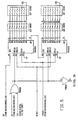
- the digital chip is shown in diagram form in figure o.
- the system is driven by an external 16 MHz crystal.
- the crystal clock feeds a pair of binary rate multipliers, whose output frequencies are controlled by data written into their counters by the control microprocessor.
- the output of the binary rate multi pliers feeds a timer chain which generates two designated carrier frequencies, as wall as their third, fifth, and seventh harmonics Thonn harmonion are added together with the fundamental carrier, appropriately weighted, in the analog chip to produce a nearly sinusoidal carrier.
- several clocks are derived for data reception and decoding: for each of the two designated frequencies, both in-phase and quadrature clocks are developed; and clocks for the low pass filters and for the bandpass filters are generated, whose frequency is determined by the bit rate commanded by the microprocessor.
- Transmission is controlled by the microprocessor, through PTT (push-to-talk) pin which enables output, and through the data pin which controls the output of one or zero.
- Data provided by the microprocessor is manchester-encoded by the microcontroller, which outputs the appropriate carrier sequence together with its harmonics.
- the received signal enters the digital chip as a 3-bit digitized signal, plus overflow from the analog chip's A/D converter.
- This data is run in parallel through four mixers, for in-phase and quadrature components of each of the two designated frequencies. These are implemented by exclusive-OR of the input with the clocks.
- the I and Q components are then run in parallel through four lowpass filters, to generate magnitude signals for each.
- the results are fed to a system of comparators, which compares the sum of I and Q energy on each of the two frequencies, and outputs a signal corresponding to the frequency with higher energy.
- This is a representation of manchester-encoded data; it is decoded and output as data to the microprocessor (manchester-encoded data is also available to the microprocessor, but is not currently used).
- Bit synchronization is obtained through a bandpass filter feedback loop, which uses an initial synchronization pattern at the beginning of each packet to lock onto the f0-f1 transitions in the received signal, and synchronizes the integrate-and dump function in the comparator and the Manchester decoding accordingly.
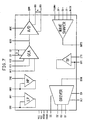
- Figure 7 is a block diagram of the analog chip. It shows the receive filter broadband operational amplifiers, which are connected through external resistors and capacitors as shown in Figure 3.
- the broadband filtering is accomplished through series low pass and high pass elements.
- Inputs C0 through C2 switch difference values of feedback resistors into the gain path, permitting gain to be set in db steps from 3 to so db.
- This signal is then fed to the A/D converter, an conventional flash converter design clocked at 1 Mhz. (Its digital portion is in the digital chip.
- FSQWV, 3F, 5F and 7F clocks are combined in the wave-shaper, which adds them together with appropriate relative gain to approximate a sine wave of frequency of . This is passed through an additional filter stage, and then to the driver which interfaces to the external power amplifier/driver stage.
- This section amplifies the output of the transmit carrier generation logic and applies it to the AC line coupling network. It consists primarily of Q1 through Q4 shown on Figure 4, and is straightforward.
- This passive network provides coupling to the AC line. It is designed to provide relatively little voltage drop and phase distortion when presented with the power line's impedance at 20 to 90 KHz. It is shown in Figure 5.
- the coupler For input signals from the AC line, the coupler is designed to attenuate so by at least 100 db, provide reasonably flat frequency response across the operating range of 9 - 90 KHz, present a high impedance to the line in the operating frequency range, and avoid ringing in response to high energy impulse noise. Protection is provided by MOV1, D1, D2, D3.
- the board version of the system includes a power supply, and various LEDs and dip switches intended to facilitate installation. These are detailed in Figures 4.
- these processes comprise a feedback control system which causes communications to operate in that portion of the available apectrum which will permit the greatest data rate to be used with acceptable error rate.
- This section describes the spectrum allocation, the coding of information bits, and the processing required for system management at the bit level.
- Each bit is encoded as a combination of two frequencies, together comprising a manchester-encoded bit of information. It is desirable to set up the channels to be contiguous but monovorinpping, to take full advantage of the available spectrum without making two adjacent channels vulnerable to the same single-frequency noise source. This leads to the following frequency allocation: tune f0 (Hz) f1 (Hz) 0 76200 50000 1 51142 38095 2 42857 28571 3 32142 21420
- the microprocessor will load a code for each of the two frequencies of the current tune.
- the gain associated with each frequency is adjustable, based on bit error rate as measures over a small number of packets. This section describes the proggen.
- this loop is fast compared to the bit rate and frequency changeloop; that is, changes to gain are made more readily than changes to bit rate and frequency, to avoid thrashing between the two dimensions of the system.
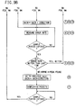
- the gain Upon reset, prior to network acquisition, the gain is set at its middle value. It is then adjusted based on the odurrance or bytes received in error, as determined by the parity bit. A change is made to the gain after each four packets received. Since a gain setting either too high or too low will produce inferior performance, a two-step peak-finding algorithm is used:
- the system starts operating at a gain of 4, and measures the error rate for four successive received packets (1).
- bit error rate was set to zero, so when the new measurement is compared to the previous bit error rate, it will be worse (2). This causes the variable "direction" to be reversed in sign, it is then +1.
- the gain is incremethod to a value or 3, (3) and error rate is measured for another four packets (4).
- a worse measurement is obtained, causing direction to be again reversed to -1, (6) and gain set to 4, (7).
- the next measurement (8) produces another improvement in error rate (9), so gain is again decremented (10) to 3.
- the next measurement (11) again improves gain (12), and gain is again decremented (13) to 2.
- the slave controls its gain autonomously, but changes bit rate and frequency only in response to a command from the master, or during network acquisition, if it loses the network or has just been powered on.
- the following discussion thus applies only to the master.
- the master starts at the highest bit rate.
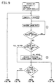
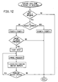
- BRCNT is an a bit number. If DRCNT exceeds a upper threshold, then the bit rate is decreased, unless the lowest bit rate is already in use. In this case, frequency is changed. If URCNT drops below a lower throuhold, then bit rate is increased. If bit rate is maximum, only the first threshold applies.
- the master starts the network at the highest frequency channel not occupied by another master address. It will drop to another frequency channel is the system is currently operating on the lowest bit rate, and a figure of merit, FHCNT, exceeds a threshold. FHCNT is calculated similarly to BRCNT, as a function of packet retries. The master will rotate through available frequency channels; collision with existing networks with other master addresses will be treated in the same way as unacceptable FHCNT, resulting in shift to another frequency channel. The logic is shown in Figure 12.
- the current bit rate and frequency are designated in each packet.
- the master When a change is requested by the master, it transmits four packets with the new code on the old bit rate and frequency, and then changes to the new set. Those slaves hearing the packets change immediately; those that do not lose the network, and enter the network acquisition routine.
- This section describes the process through which a network is initialized, and through which additional subscribers join the network.
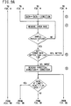
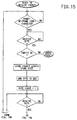
- a slave Upon initialization, a slave must search for and find the tune and bit rate currently in use. It proceeds as described below, and illustrated in Figure 13.
- All tunes are searched, starting with the highest.
- bit rate is searched, starting with the highest.
- gain is searched highest to lowest. If a valid (error code checks correct) sequence is obtained during this process, then the slave knows the tune and switches to it, entering run made. If not, the slave proceeds to search the tunes bit rates and gains, remaining on each combination for four packet times. This process is repeated until a valid packet is received.
- the master starts by performing the slave initialization sequence to see if a network with the same network address already exists. If so, it is internally disables. This is intended to prevent seizure of a network by a master in malevolent hands.
- the network In order to keep the system gain and tune melection optimal, the network will always be active. In network mode, the master runs internal test (software loopback) whenever there is no host traffic required.
- Software loopback or test mode will operate as follows: For the first cycle, the master will attempt to access all 255 slave addressees. Subsequently it will scan only up to the highest address which responded. Every TDD cycles, it will search the rull set, (it is required that the user pack addresses contiguously upward from 1 for efficient operation). Each time it accesses a slave, it will send a packet of test data which the slave will echo. The master will process to the next slave address upon correct receipt of the echo.
- the tune control will be performed as described above.
- power lines are characterized by impulsive noise, which by definition occupies all frequency hands for relatively short periods, often less than one bit time. This noise, tends to be 100 or 120 Hz synchronous, due to its origin.
- a 27 bit error code is employed, consisting of three bytes plus byte parity. They consist of a cumulative XOR of the bytes in the packet, followed by an XOR of the bytes in the packet with a one-byte left rotate after each byte is added, followed by an XOR of the bytes in the packet with a right rotate after each XOR. This allows implementation in software in real time, and provides good performance with the overlay technique. In implementations with a more powerful processor, a stronger code will be appropriate.
- the receiver will continue to collect data for the remainder of the packet, and will store those bytes subject to successful error correction in the receive buffer. However, if the first byte, which contains the packet length, is corrupted, the packet must be abandoned.
- This approach allows the system to communicate successfully even in a noise environment which precludes a packet from ever being received with only correctable errors, as long as each byte gets through once.
- This section describes the operation of the link layer of the system, separately for transparent mode and network mode.
- Transparent mode is extremely simple: Data transmitted into the master by its host is transferred to the network as a modulated bit stream, which is decoded by all slaves which can hear it and output as serial data to their hosts. similarly, data transmitted into a slave by its host is transferred across the network and comes out all other units.
- Network mode implements a polled, master slave system capable of both cyclic polling operation and of a point-to-point connection.
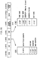
- Each packet is comprised of four bytes plus 0 to 17 data bytes, with the quantity variable.
- Each byte is supplemented by a parity bit. This is illustrated in Figure 16.
- the fields are:
- control_1 byte is further subdivided as follows:
- Packets are of variable length, and the length (in terms of data bytes) is the lower nibble of the control byte.
- the ack/nak bit is used to command retransmission of a destroyed block.
- the sequence bit allows the system to avoid confusing retries with new data.
- the new_address bit is 1 on the first block being sent to a slave in a particular link process; it signals to the slave that this is a new link.
- the slave address field is used by the slave to match messages intended for it. It ignores messages not bearing its own address, with the exception of address 0.
- Address 0 is used for broadcast: All slaves accept a message with this address, but none respond to it.
- control_3 byte is organised as follows :
- the tune code is a 2-bit code denoting the tune currently in use by the network. It is followed by a another 2-bit code for bit rate.
- the next bit is used by the slave to indicate that although the link is good, the slave's host is not accepting data as fast as it is being delivered, due to flow control or a difference in data rates, and that the master should therefore send no new data, although it may keep the link active.
- the next bit indicates origin of the message 1 for master, and zero for slave.
- the top 2 bits of this byte specify one or a master (or network) addresses. These are used to allow concurrent operation of multiple, independent networks on the same physical channel without confusion, either for store-and-forward purposes or to allow increased use or the bandwidth.
- the error code is appended at the end of the packet, and is used to verify validity of the whole packet. Different words of the packet may have been delivered on different retires of the packet in a noisy environment.
- the protocol implements the various link commands described below. These allow creation of three types of links:
- Network test can be viewed as a special case of a polling cycle, in which data is not transferred to the host device.
- Polling is in turn a special case of the continuous link, in which the link is discontinued automatically after receipt of one valid packet from the slave, and the next slave in tho specified range is then connected. It shares the same routines for circuit establishment and error control. These routines are essentially the same as those described in Patent 4,597,082.
- the master distinguished the commands from data by the status of the control/data line.
- the system will assert its ERROR pin (or BREAK if in serial mode) if an illegal command or syntax is received.
- the slave does not accept or act on commands except for STATUS and EXTERNAL FH. If its control/data line is in control state, it treats data received as a destination address to be included in subsequent packets. If its internal buffer (15 bytes is filled, subsequent data will be ignored, and additional writes to the chip will produce an error.
- This mode sends a packet to each slave within the specified range; the slave performs a software loopback to the master; the master checks for errors and reports error rate.
- the same blook-ahead acknowledgment protocol will be used as in the case of polling and transparent link communications.
- the primary purpose of this mode in to provide current data a spectrum performance so the FH algorithms will remain optimized in periods of low ussage. It al execute until another command received.
- Link status is success or failure in establishing the link.
- the ERROR pin will be assorted (parallel mode) or a BREAK character will be output (serial mode).
- the unit contains 15 bytes of buffering. If the input data rate is such that this buffer is filled, the TRANSMIT BUFFER AVAILABLE line will not be asserted, providing flow control.
- This command is identical to the transparent link, except that no acknowledgment is expected or received from slaves.
- the broadcast address is 00. Any unit receiving data addressed to 00 will output it to its host, if it is free if errors after error correction.
- Command syntax ⁇ op code> ⁇ address> Command response; ⁇ address> ⁇ link Status> ⁇ Link status > is always OK.
- the system Upon power-up or hardware reset, the system must receive an initialization sequence or it will do nothing. This sequence tells it whether it is a master or slave. If a slave, it also tell it its address, and an address filter (applied to the destination address field in received packets) to be used in passing network data bearing other addressed to its host. If it is a master, it is told the address range over which the system is working.
- command syntax to slave ⁇ op code> ⁇ master/slave> ⁇ own address> ⁇ destination address filter>
- command syntax to master ⁇ op code> ⁇ master/slave> ⁇ low address> ⁇ destination address filter> command response: none
- Chip status indicates the current state of the chip, and may be used by the host to obtain additional information when the ERROR pin (or serial BREAK) is asserted.
- the link status command valid for both master and slave, causes output of current Fil tune, and relative error rate data on the frequencies or the tune, each expressed as a two-byte number.
- This command allows external setting of the frequency set in use. It over-rides the internal FH algorithms, for test and debug purposes, and to allow operation of the system on a fixed-frequency basis for compatibility with possible future, fixed-frequency nodes.
- This command allows external setting of the bit rate set in use. It over-rides the internal FH algorithms, for test and debug purposes, and to allow operation of the system on a fixed-frequency basis for compatibility with possible future, fixed-frequency nodes.
- Command syntax ⁇ op code> ⁇ bit rate to use> if "0" is entered in the bit rate field, the internal FH algorithms will be re-enabled. command response: none
- the IC/SSTM chip set comprising the IC/SSTM analog chip ICSSTM 1003, IC/SSTM digital chip ICSSTM 1002, and the IC/SSTM controller chip ICSSTM 1001 are manufactured by National Semiconductor corporation of Santa Clara, California.
- the ICSSTM 1001 chip is a programmed National Semiconductor COP884EG microcontroller that controls the adaptive gain setting, bit rate setting, frequency hopping, host interface, and link layer protocols.
Landscapes
- Engineering & Computer Science (AREA)
- Computer Networks & Wireless Communication (AREA)
- Signal Processing (AREA)
- Power Engineering (AREA)
- Physics & Mathematics (AREA)
- Aviation & Aerospace Engineering (AREA)
- Electromagnetism (AREA)
- Radar, Positioning & Navigation (AREA)
- Remote Sensing (AREA)
- General Physics & Mathematics (AREA)
- Automation & Control Theory (AREA)
- Communication Control (AREA)
- Detection And Prevention Of Errors In Transmission (AREA)
Claims (7)
- Système de communication comprenant un émetteur et un récepteur et dans lequel des paquets d'informations binaires codées incluant des codes d'erreur sont émis d'un émetteur vers un récepteur à au moins l'une d'une pluralité de fréquences modulées, et le récepteur envoie à l'émetteur un signal d'erreur lorsque le récepteur établit qu'un paquet a été reçu avec une erreur, caractérisé en ce que l'émetteur comprend:A) des moyens pour régler la cadence binaire de transmission sur l'une d'une pluralité de cadences binaires entre des limites supérieure et inférieure;B) des moyens pour maintenir une variable associée à la cadence d'erreur sur les bits (BRCNT) possédant des limites supérieure et inférieure, et miss à jour comme suit, (N-1) indiquant la valeur (BRCNT) actuelle et (N) indiquant la nouvelle valeur BRCNT,
BRCNT(N) = BRCNT(N-1)+1 lorsqu'un paquet a été reçu avec une erreur,
BRCNT(N) = BRCNT(N-1)/2 lorsqu'un paquet a été reçu sans erreur,
et pour décrémenter le réglage de la cadence binaire lorsque la valeur BRCNT atteint la limite supérieure et pour incrémenter le réglage de la cadence binaire lorsque la valeur BRCNT atteint la limite inférieure; etC) des moyens pour modifier au moins une fréquence utilisée lors de la transmission du paquet suivant, lorsque la valeur BRCNT atteint la limite supérieure et que la cadence binaire utilisée dans le paquet contenant l'erreur possède la cadence binaire minimale disponible. - Système selon la revendication 1, caractérisé en ce que le récepteur utilise une détection de bits d'intégration et de vidage.
- Système selon la revendication 1 ou la revendication 2, dans lequel le récepteur utilise la commande automatique de gain pour recevoir une information contrôlée codée par un binaire, dont la parité est contrôlée, dans des paquets successifs, caractérisé en ce qu'un récepteur comporteA) des moyens pour déterminer le taux d'erreurs sur les bits, qui apparaít dans des paquets reçus par analyse des paquets en rapport avec des erreurs pendant une période d'échantillonnage sélectionnée parmi une pluralité de périodes d'échantillonnage successives, et pour mémoriser ledit taux;B) des moyens pour comparer ledit taux d'erreurs sur les bits dans une période d'échantillonnage apparaissant avant la période d'échantillonnage sélectionnée; etC) des moyens pour modifier le gain du récepteur dans la même direction que celle dans laquelle il a été modifié précédemment lorsque le taux actuel d'erreurs sur les bits est inférieur au taux mesuré d'erreurs sur les bits et pour modifier le gain dans le sens opposé lorsque le taux actuel d'erreurs sur les bits est supérieur au taux d'erreurs sur les bits au taux mesuré antérieurement d'erreurs sur les bits.
- Système selon la revendication 3, caractérisé parD) des moyens pour maintenir le gain à la même valeur réglée pendant un nombre prédéterminé de périodes successives parmi lesdites périodes d'échantillonnage après modification du gain dans ladite direction opposée.
- Système selon la revendication 3 ou la revendication 4, caractérisé en ce que ladite période d'échantillonnage est un nombre de paquets reçus.
- Système selon l'une quelconque des revendications précédentes, caractérisé par une pluralité de modems esclaves comprenant chacun un récepteur essentiellement identique audit récepteur, et connectés chacun à un ordinateur central, ledit récepteur comprenant en outre:A) des moyens pour recevoir des paquets d'informations codées binaires à ladite pluralité de fréquences modulées;B) des moyens pour effectuer une recherche dans lesdites fréquences en ce qui concerne les paquets contenant l'une d'une pluralité d'adresses maítre et pour transmettre, à l'ordinateur central, des paquets contenant ladite une adresse maítre.
- Système selon la revendication 6, caractérisé en outre parC) un modem maítre possédant une adresse maítre spécifique et comprenanta) des moyens pour effectuer une recherche dans lesdits canaux, et s'invalider lorsqu'est reçu un paquet contenant ladite adresse de modem maítre spécifique à partir d'un autre maítre.
Applications Claiming Priority (3)
| Application Number | Priority Date | Filing Date | Title |
|---|---|---|---|
| US920110 | 1992-07-24 | ||
| US07/920,110 US5448593A (en) | 1984-03-06 | 1992-07-24 | Frequency hopping time-diversity communications systems and transceivers for local area networks |
| PCT/US1993/006911 WO1994003002A1 (fr) | 1992-07-24 | 1993-07-23 | Systemes de communication en diversite dans le temps a saut de frequence |
Publications (3)
| Publication Number | Publication Date |
|---|---|
| EP0651925A1 EP0651925A1 (fr) | 1995-05-10 |
| EP0651925A4 EP0651925A4 (fr) | 1997-05-21 |
| EP0651925B1 true EP0651925B1 (fr) | 2004-02-18 |
Family
ID=25443181
Family Applications (1)
| Application Number | Title | Priority Date | Filing Date |
|---|---|---|---|
| EP93918322A Expired - Lifetime EP0651925B1 (fr) | 1992-07-24 | 1993-07-23 | Systemes de communication en diversite dans le temps a saut de frequence |
Country Status (5)
| Country | Link |
|---|---|
| US (1) | US5448593A (fr) |
| EP (1) | EP0651925B1 (fr) |
| AU (1) | AU4781393A (fr) |
| DE (1) | DE69333418T2 (fr) |
| WO (1) | WO1994003002A1 (fr) |
Families Citing this family (72)
| Publication number | Priority date | Publication date | Assignee | Title |
|---|---|---|---|---|
| GB9316996D0 (en) * | 1993-08-16 | 1993-09-29 | D2B Systems Co Ltd | Communication bus system and station for use in such system |
| FI110042B (fi) * | 1993-10-04 | 2002-11-15 | Nokia Corp | Solukkoradiojärjestelmä |
| US5614914A (en) * | 1994-09-06 | 1997-03-25 | Interdigital Technology Corporation | Wireless telephone distribution system with time and space diversity transmission for determining receiver location |
| FR2728412B1 (fr) * | 1994-12-16 | 1997-03-14 | Sgs Thomson Microelectronics | Circuit de transmission de donnees sur le reseau electrique a faible seuil de reception |
| US5818821A (en) | 1994-12-30 | 1998-10-06 | Intelogis, Inc. | Universal lan power line carrier repeater system and method |
| US6975582B1 (en) | 1995-07-12 | 2005-12-13 | Ericsson Inc. | Dual mode satellite/cellular terminal |
| US5663957A (en) * | 1995-07-12 | 1997-09-02 | Ericsson Inc. | Dual mode satellite/cellular terminal |
| FR2736780B1 (fr) | 1995-07-13 | 1997-09-26 | Sgs Thomson Microelectronics | Circuit d'affectation d'un canal de transmission sur le reseau electrique |
| FR2736781B1 (fr) * | 1995-07-13 | 1997-09-26 | Sgs Thomson Microelectronics | Circuit de transmission de donnees binaires sur le reseau electrique utilisant plusieurs canaux de transmission |
| SE506064C2 (sv) * | 1996-02-29 | 1997-11-03 | Ericsson Telefon Ab L M | Förfarande och anordning för uppkoppling av en förbindelse i ett radiokommunikationsnät |
| US6006075A (en) * | 1996-06-18 | 1999-12-21 | Telefonaktiebolaget L M Ericsson (Publ) | Method and apparatus for transmitting communication signals using transmission space diversity and frequency diversity |
| JPH1070780A (ja) * | 1996-08-27 | 1998-03-10 | Uniden Corp | データ収集システム |
| US6154499A (en) * | 1996-10-21 | 2000-11-28 | Comsat Corporation | Communication systems using nested coder and compatible channel coding |
| GB9805765D0 (en) * | 1997-06-10 | 1998-05-13 | Northern Telecom Ltd | Data transmission over a power line communications system |
| JP3137181B2 (ja) * | 1997-06-23 | 2001-02-19 | 日本電気株式会社 | 受信機及びその受信方法 |
| US5912921A (en) * | 1997-08-20 | 1999-06-15 | Intermec Ip Corp. | Concurrent multiple data rate communications in a wireless local area network |
| US5970127A (en) | 1997-10-16 | 1999-10-19 | Phonex Corporation | Caller identification system for wireless phone jacks and wireless modem jacks |
| US6055435A (en) | 1997-10-16 | 2000-04-25 | Phonex Corporation | Wireless telephone connection surge suppressor |
| US6295461B1 (en) | 1997-11-03 | 2001-09-25 | Intermec Ip Corp. | Multi-mode radio frequency network system |
| US6107912A (en) | 1997-12-08 | 2000-08-22 | Phonex Corporation | Wireless modem jack |
| GB2335335A (en) * | 1998-03-13 | 1999-09-15 | Northern Telecom Ltd | Carrying speech-band signals over power lines |
| US6067646A (en) * | 1998-04-17 | 2000-05-23 | Ameritech Corporation | Method and system for adaptive interleaving |
| US6480510B1 (en) | 1998-07-28 | 2002-11-12 | Serconet Ltd. | Local area network of serial intelligent cells |
| US6246868B1 (en) | 1998-08-14 | 2001-06-12 | Phonex Corporation | Conversion and distribution of incoming wireless telephone signals using the power line |
| US6243571B1 (en) | 1998-09-21 | 2001-06-05 | Phonex Corporation | Method and system for distribution of wireless signals for increased wireless coverage using power lines |
| US6480497B1 (en) | 1998-11-23 | 2002-11-12 | Ricochet Networks, Inc. | Method and apparatus for maximizing data throughput in a packet radio mesh network |
| IL127223A (en) | 1998-11-24 | 2002-08-14 | Systel Dev And Ind Ltd | Power-line digital communication system |
| US6567474B1 (en) * | 1999-03-02 | 2003-05-20 | Phonex Corporation | Digital wireless phone/modem jack capable of communications over the power lines using differential binary phase shift keying (DBPSK) |
| GB2348349A (en) * | 1999-03-20 | 2000-09-27 | Rover Group | A control system |
| EP1096695B1 (fr) | 1999-10-28 | 2012-03-21 | STMicroelectronics S.r.l. | Emetteur/récepteur à canaux multiples pour signaux numériques sur lignes d'alimentation |
| US6842459B1 (en) | 2000-04-19 | 2005-01-11 | Serconet Ltd. | Network combining wired and non-wired segments |
| US6456192B1 (en) * | 2000-04-19 | 2002-09-24 | Phonex Broadband Corporation | Method and system for power line null detection and automatic frequency and gain control |
| US7549107B1 (en) * | 2000-05-18 | 2009-06-16 | Broadcom Corporation | Interleaved reed solomon coding for home networking |
| JP3693896B2 (ja) * | 2000-07-28 | 2005-09-14 | 三菱電機株式会社 | 通信方法および通信システム |
| JP2002077562A (ja) * | 2000-08-31 | 2002-03-15 | Canon Inc | 画像通信装置 |
| US6888819B1 (en) * | 2000-10-04 | 2005-05-03 | Yitran Communications Ltd. | Media access control utilizing synchronization signaling |
| DE10061585B4 (de) * | 2000-12-11 | 2004-01-29 | Siemens Ag | Anordnung und Verfahren zur Datenkommunikation in einem Energieverteilungsnetz |
| US7027418B2 (en) * | 2001-01-25 | 2006-04-11 | Bandspeed, Inc. | Approach for selecting communications channels based on performance |
| WO2002063341A1 (fr) | 2001-02-02 | 2002-08-15 | Dbi Corporation | Telemetrie de fond et systeme de commande |
| KR100395745B1 (ko) * | 2001-05-16 | 2003-08-27 | 주식회사 젤라인 | 전력선 통신시스템의 다중 채널 주파수 시프트 키잉변복조장치 |
| ES2187274B1 (es) * | 2001-05-17 | 2004-08-16 | Diseño De Sistemas En Silicio, S.A. | Sistema de control automatico de ganancia para sistema de transmision digital ofdm multiusuario sobre red electrica. |
| DE10147772C1 (de) * | 2001-09-27 | 2003-09-11 | Siemens Ag | Verfahren zum Betreiben eines Übertragungssystems und Übertragungssystem in einem Energieversorgungsnetz |
| DE10147916C1 (de) * | 2001-09-28 | 2003-05-28 | Siemens Ag | Verfahren und Übertragungseinrichtung zum Erkennen des Sendezustandes von an Energieversorgungsleitungen angeschlossenen Übertragungseinrichtungen |
| DE10147915C1 (de) * | 2001-09-28 | 2003-06-26 | Siemens Ag | Verfahren zum Verwalten und Betreiben von Kommunikationsnetzen über Energieversorgungsnetze |
| JP2003114133A (ja) * | 2001-10-05 | 2003-04-18 | Pioneer Electronic Corp | 通信ナビゲーション方法、通信ナビゲーションシステム、端末装置 |
| ES2550821T3 (es) * | 2002-01-24 | 2015-11-12 | Panasonic Corporation | Método de y sistema para comunicaciones de portadora por línea eléctrica |
| JP3931666B2 (ja) * | 2002-01-24 | 2007-06-20 | 松下電器産業株式会社 | 電力線搬送通信装置 |
| KR100490640B1 (ko) * | 2002-07-25 | 2005-05-24 | 넷디바이스 주식회사 | 전력선 통신장치 |
| US7277411B2 (en) | 2002-08-21 | 2007-10-02 | D.S.P. Group Ltd. | Method and system for transmitting and receiving data in a TDMA frequency hopping system utilizing frequency diversity |
| JP3440095B1 (ja) * | 2002-08-23 | 2003-08-25 | 富士通株式会社 | データ伝送装置及びデータ伝送方法 |
| JP4098606B2 (ja) * | 2002-11-29 | 2008-06-11 | 三菱電機株式会社 | 電力線通信装置 |
| ES2212744B2 (es) | 2003-01-10 | 2005-03-16 | Diseño De Sistemas En Silicio, S.A. | Procedimiento de sincronizacion en el dominio del tiempo y de la frecuencia de multiples equipos en un sistema de transmision con modulacion ofdm. |
| US20040141616A1 (en) * | 2003-01-17 | 2004-07-22 | Ibm Corporation | Security object with encrypted, spread spectrum data communications |
| IL154921A (en) | 2003-03-13 | 2011-02-28 | Mosaid Technologies Inc | A telephone system that includes many separate sources and accessories for it |
| US7474677B2 (en) | 2003-08-12 | 2009-01-06 | Bose Corporation | Wireless communicating |
| US8442019B2 (en) | 2003-08-12 | 2013-05-14 | Bose Corporation | Method and apparatus for avoiding wireless audio signal transmission interferences |
| GB2407928B (en) * | 2003-11-07 | 2006-10-18 | Eric Atherton | Signalling method |
| US8223880B2 (en) * | 2005-03-16 | 2012-07-17 | Analog Devices, B.V. | System and method for power line communication |
| RU2342774C2 (ru) * | 2005-07-27 | 2008-12-27 | Общество с ограниченной ответственностью "Источник-Про" | Способ передачи телемеханической информации от нескольких контрольных пунктов по общему физическому каналу связи |
| JP4872415B2 (ja) * | 2006-03-31 | 2012-02-08 | 日本電気株式会社 | 信号劣化検出方法、信号復旧検出方法及びそれらの装置並びにトラフィック伝送システム |
| US8023575B2 (en) * | 2006-06-13 | 2011-09-20 | Bandspeed, Inc. | Approach for spectrum analysis in a receiver |
| US8885814B2 (en) * | 2006-07-25 | 2014-11-11 | Broadcom Europe Limited | Feedback impedance control for driving a signal |
| US10013381B2 (en) | 2006-08-31 | 2018-07-03 | Bose Corporation | Media playing from a docked handheld media device |
| EP2109986A2 (fr) * | 2007-02-05 | 2009-10-21 | Bandspeed, Inc. | Approche pour atténuer les effets de points d'accès sans fil corrompus |
| EP2211479A1 (fr) | 2009-01-15 | 2010-07-28 | ABB Technology AG | Système et procédé de communications |
| US8447252B2 (en) * | 2009-01-21 | 2013-05-21 | Bandspeed, Inc. | Adaptive channel scanning for detection and classification of RF signals |
| US8849213B2 (en) * | 2009-01-21 | 2014-09-30 | Bandspeed, Inc. | Integrated circuit for signal analysis |
| US20100188265A1 (en) * | 2009-01-23 | 2010-07-29 | Hill Lawrence W | Network Providing Vehicles with Improved Traffic Status Information |
| RU2401515C1 (ru) * | 2009-02-12 | 2010-10-10 | Открытое акционерное общество "Российская корпорация ракетно-космического приборостроения и информационных систем" (ОАО "Российские космические системы") | Модуляционная схема несущей частоты |
| US8023899B2 (en) | 2009-04-30 | 2011-09-20 | Bandspeed, Inc. | Approach for selecting communications channels in communication systems to avoid interference |
| JP5573571B2 (ja) * | 2009-11-13 | 2014-08-20 | ソニー株式会社 | 無線通信装置、無線通信システム、プログラム、および無線通信方法 |
| CN102347811B (zh) * | 2011-11-04 | 2013-10-23 | 兆讯恒达微电子技术(北京)有限公司 | 一种电力线通信信道脉冲噪声检测方法 |
Family Cites Families (14)
| Publication number | Priority date | Publication date | Assignee | Title |
|---|---|---|---|---|
| US4049914A (en) * | 1976-08-30 | 1977-09-20 | Rockwell International Corporation | Frequency division multiplex voice communication apparatus with hierarchy of stations |
| US4210780A (en) * | 1978-03-27 | 1980-07-01 | The Mitre Corporation | Multiple access digital communications system |
| US4291410A (en) * | 1979-10-24 | 1981-09-22 | Rockwell International Corporation | Multipath diversity spread spectrum receiver |
| US4387461A (en) * | 1981-03-11 | 1983-06-07 | Ford Aerospace & Communications Corporation | Experientially determined signal quality measurement device for antipodal data |
| US4580276A (en) * | 1983-08-05 | 1986-04-01 | Consultant's Choice Inc. | System and method for transporting data |
| US5168510A (en) * | 1984-03-06 | 1992-12-01 | Comsource Systems | Spread spectrum-time diversity communications systems and transceivers for multidrop area networks |
| US4597082A (en) * | 1984-03-06 | 1986-06-24 | Controlonics Corporation | Transceiver for multi-drop local area networks |
| US4756007A (en) * | 1984-03-08 | 1988-07-05 | Codex Corporation | Adaptive communication rate modem |
| JPH0740702B2 (ja) * | 1986-03-06 | 1995-05-01 | 日本電気株式会社 | リモ−トテスト回路 |
| CA1290020C (fr) * | 1987-02-09 | 1991-10-01 | Steven Messenger | Reseau local sans fil |
| US5029182A (en) * | 1988-10-24 | 1991-07-02 | Hughes Aircraft Company | Automatic gain control (AGC) for frequency hopping receiver |
| US5048054A (en) * | 1989-05-12 | 1991-09-10 | Codex Corporation | Line probing modem |
| US5093842A (en) * | 1990-02-22 | 1992-03-03 | Harris Corporation | Mechanism for estimating Es/No from pseudo error measurements |
| US5184349A (en) * | 1991-01-16 | 1993-02-02 | Motorola, Inc. | Amplitude control of a burst signal in a receiver |
-
1992
- 1992-07-24 US US07/920,110 patent/US5448593A/en not_active Expired - Fee Related
-
1993
- 1993-07-23 WO PCT/US1993/006911 patent/WO1994003002A1/fr not_active Ceased
- 1993-07-23 EP EP93918322A patent/EP0651925B1/fr not_active Expired - Lifetime
- 1993-07-23 AU AU47813/93A patent/AU4781393A/en not_active Abandoned
- 1993-07-23 DE DE69333418T patent/DE69333418T2/de not_active Expired - Fee Related
Also Published As
| Publication number | Publication date |
|---|---|
| AU4781393A (en) | 1994-02-14 |
| EP0651925A1 (fr) | 1995-05-10 |
| WO1994003002A1 (fr) | 1994-02-03 |
| DE69333418T2 (de) | 2004-12-02 |
| US5448593A (en) | 1995-09-05 |
| EP0651925A4 (fr) | 1997-05-21 |
| DE69333418D1 (de) | 2004-03-25 |
Similar Documents
| Publication | Publication Date | Title |
|---|---|---|
| EP0651925B1 (fr) | Systemes de communication en diversite dans le temps a saut de frequence | |
| US5168510A (en) | Spread spectrum-time diversity communications systems and transceivers for multidrop area networks | |
| US5046066A (en) | Wireless local area network | |
| US6006017A (en) | System for determining the frequency of repetitions of polling active stations relative to the polling of inactive stations | |
| US4785448A (en) | System for communicating digital data on a standard office telephone system | |
| CA1243730A (fr) | Modem d'ordinateur sans fil | |
| JP3577393B2 (ja) | 高速データ通信モデム | |
| US4479215A (en) | Power-line carrier communications system with interference avoidance capability | |
| EP1292060B1 (fr) | Transmission de données à sous-canal pour la signalisation | |
| EP0596523A2 (fr) | Transfert de données à grande vitesse par câbles à paires torsadées | |
| US6343071B1 (en) | Wireless desktop area network system | |
| US4763357A (en) | Method and apparatus for providing secure electronic communications | |
| EP0273080A1 (fr) | Procédé et dispositif pour interrogation à grande vitesse | |
| US9332552B2 (en) | Frequency agility for wireless embedded systems | |
| EP0042650B1 (fr) | Système émetteur-récepteur pour le trafic télex par des voies de communication selon le système ARQ avec répétition groupée | |
| JP2001156685A (ja) | 電力線通信システム | |
| JP3685740B2 (ja) | データ通信装置管理装置及びデータ通信装置管理方法 | |
| JPH0578054B2 (fr) | ||
| US7421051B2 (en) | Radio communication system and method, wireless network forming device, radio transmission unit and method, and radio reception unit and method | |
| AU597732B2 (en) | Decentralized line reservation interface within a local area network | |
| KR0165440B1 (ko) | 폴링통신방법 | |
| EP0803152A1 (fr) | Systeme de reseau de zone de bureau sans fil | |
| JPH0424899B2 (fr) | ||
| EP1738480A1 (fr) | Dispositif utilise dans un systeme a evasion de frequence | |
| RU240946U1 (ru) | Устройство для связи |
Legal Events
| Date | Code | Title | Description |
|---|---|---|---|
| PUAI | Public reference made under article 153(3) epc to a published international application that has entered the european phase |
Free format text: ORIGINAL CODE: 0009012 |
|
| 17P | Request for examination filed |
Effective date: 19950224 |
|
| AK | Designated contracting states |
Kind code of ref document: A1 Designated state(s): CH DE FR GB LI SE |
|
| A4 | Supplementary search report drawn up and despatched |
Effective date: 19970404 |
|
| AK | Designated contracting states |
Kind code of ref document: A4 Designated state(s): CH DE FR GB LI SE |
|
| 17Q | First examination report despatched |
Effective date: 19991209 |
|
| GRAH | Despatch of communication of intention to grant a patent |
Free format text: ORIGINAL CODE: EPIDOS IGRA |
|
| GRAS | Grant fee paid |
Free format text: ORIGINAL CODE: EPIDOSNIGR3 |
|
| GRAA | (expected) grant |
Free format text: ORIGINAL CODE: 0009210 |
|
| AK | Designated contracting states |
Kind code of ref document: B1 Designated state(s): CH DE FR GB LI SE |
|
| REG | Reference to a national code |
Ref country code: GB Ref legal event code: FG4D |
|
| REG | Reference to a national code |
Ref country code: CH Ref legal event code: EP |
|
| REF | Corresponds to: |
Ref document number: 69333418 Country of ref document: DE Date of ref document: 20040325 Kind code of ref document: P |
|
| REG | Reference to a national code |
Ref country code: SE Ref legal event code: TRGR |
|
| RAP2 | Party data changed (patent owner data changed or rights of a patent transferred) |
Owner name: DBI CORPORATION |
|
| PGFP | Annual fee paid to national office [announced via postgrant information from national office to epo] |
Ref country code: DE Payment date: 20040806 Year of fee payment: 12 |
|
| ET | Fr: translation filed | ||
| REG | Reference to a national code |
Ref country code: GB Ref legal event code: 732E |
|
| PLBE | No opposition filed within time limit |
Free format text: ORIGINAL CODE: 0009261 |
|
| STAA | Information on the status of an ep patent application or granted ep patent |
Free format text: STATUS: NO OPPOSITION FILED WITHIN TIME LIMIT |
|
| 26N | No opposition filed |
Effective date: 20041119 |
|
| REG | Reference to a national code |
Ref country code: CH Ref legal event code: PUE Owner name: DBI CORPORATION Free format text: COMSOURCE SYSTEMS CORPORATION#472 AMHERST STREET#NASHUA, NH 03063 (US) -TRANSFER TO- DBI CORPORATION#P.O. BOX 1605, 80 SCHURTLEFF ROAD#NORTH EASTHAM, MA 02651-1605 (US) Ref country code: CH Ref legal event code: NV Representative=s name: PATENTANWAELTE FELDMANN & PARTNER AG |
|
| REG | Reference to a national code |
Ref country code: FR Ref legal event code: TP |
|
| PGFP | Annual fee paid to national office [announced via postgrant information from national office to epo] |
Ref country code: GB Payment date: 20050720 Year of fee payment: 13 |
|
| PGFP | Annual fee paid to national office [announced via postgrant information from national office to epo] |
Ref country code: FR Payment date: 20050726 Year of fee payment: 13 |
|
| PGFP | Annual fee paid to national office [announced via postgrant information from national office to epo] |
Ref country code: SE Payment date: 20050727 Year of fee payment: 13 Ref country code: CH Payment date: 20050727 Year of fee payment: 13 |
|
| PG25 | Lapsed in a contracting state [announced via postgrant information from national office to epo] |
Ref country code: DE Free format text: LAPSE BECAUSE OF NON-PAYMENT OF DUE FEES Effective date: 20060201 |
|
| PG25 | Lapsed in a contracting state [announced via postgrant information from national office to epo] |
Ref country code: GB Free format text: LAPSE BECAUSE OF NON-PAYMENT OF DUE FEES Effective date: 20060723 |
|
| PG25 | Lapsed in a contracting state [announced via postgrant information from national office to epo] |
Ref country code: SE Free format text: LAPSE BECAUSE OF NON-PAYMENT OF DUE FEES Effective date: 20060724 |
|
| PG25 | Lapsed in a contracting state [announced via postgrant information from national office to epo] |
Ref country code: LI Free format text: LAPSE BECAUSE OF NON-PAYMENT OF DUE FEES Effective date: 20060731 Ref country code: CH Free format text: LAPSE BECAUSE OF NON-PAYMENT OF DUE FEES Effective date: 20060731 |
|
| REG | Reference to a national code |
Ref country code: CH Ref legal event code: PL |
|
| EUG | Se: european patent has lapsed | ||
| GBPC | Gb: european patent ceased through non-payment of renewal fee |
Effective date: 20060723 |
|
| REG | Reference to a national code |
Ref country code: FR Ref legal event code: ST Effective date: 20070330 |
|
| PG25 | Lapsed in a contracting state [announced via postgrant information from national office to epo] |
Ref country code: FR Free format text: LAPSE BECAUSE OF NON-PAYMENT OF DUE FEES Effective date: 20060731 |