EP0652149B1 - Attelage à tampon central pour véhicules ferroviaires - Google Patents
Attelage à tampon central pour véhicules ferroviaires Download PDFInfo
- Publication number
- EP0652149B1 EP0652149B1 EP94116122A EP94116122A EP0652149B1 EP 0652149 B1 EP0652149 B1 EP 0652149B1 EP 94116122 A EP94116122 A EP 94116122A EP 94116122 A EP94116122 A EP 94116122A EP 0652149 B1 EP0652149 B1 EP 0652149B1
- Authority
- EP
- European Patent Office
- Prior art keywords
- front face
- coupling
- lower edge
- edge
- funnel
- Prior art date
- Legal status (The legal status is an assumption and is not a legal conclusion. Google has not performed a legal analysis and makes no representation as to the accuracy of the status listed.)
- Expired - Lifetime
Links
- 238000010168 coupling process Methods 0.000 title claims description 51
- 238000005859 coupling reaction Methods 0.000 title claims description 49
- 230000008878 coupling Effects 0.000 title claims description 48
- 238000009434 installation Methods 0.000 description 3
- 230000013011 mating Effects 0.000 description 2
- 125000006850 spacer group Chemical group 0.000 description 1
Images
Classifications
-
- B—PERFORMING OPERATIONS; TRANSPORTING
- B61—RAILWAYS
- B61G—COUPLINGS; DRAUGHT AND BUFFING APPLIANCES
- B61G3/00—Couplings comprising mating parts of similar shape or form which can be coupled without the use of any additional element or elements
- B61G3/16—Couplings comprising mating parts of similar shape or form which can be coupled without the use of any additional element or elements with coupling heads rigidly connected by rotatable hook plates or discs and balancing links, the coupling members forming a parallelogram, e.g. "Scharfenberg" type
Definitions
- the invention relates to a central buffer coupling according to the preamble of claim 1.
- Such a middle buffer clutch is known from DE PS 662 874.
- the arrangement of the guide horn as a guide on the funnel side and the arrangement of an inner bar as a second guide on the protruding centering projection increase the gripping area within which a coupling process with axially offset central buffer couplings can still be initiated as intended and completed after adjustment to one another Achieved compared to middle buffer couplings without guide horn.
- the installation space available for the center buffer coupling is often severely limited, and electrical coupling devices arranged on the side of the coupling head at the top or bottom must also be coupled.
- the height dimensions of the installation space are greatly restricted, but there are still high demands on the height gripping area of the center buffer coupling.
- Coupling heads without guide horn according to DE OS 29 26 301 have an almost rectangular, but for many applications too small gripping area.
- the invention is therefore based on the object of developing a central buffer coupling of the type mentioned in such a way that a sufficiently large gripping area of the coupling heads, in particular a height gripping area, is also achieved with a guide horn which is greatly shortened compared to the known prior art.
- the coupling head it is essential that a height pre-centering is carried out by the guide horn in connection with the centering projection, in particular in aligning the projecting edges of the guide horn on the gripper with the guide bevel on the underside of the centering projection of a counter coupling.
- the height is centered by engaging the guide horn on the lower edge of the end plate of the coupling head of the counter-coupling. This is the main reason why such cantilevers are long, have a large board in front of the end face and protrude beyond the side edge of the end plate. Due to the new and inventive design of the coupling head, the necessary installation space on the vehicle can be reduced in height and side dimensions.
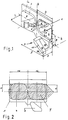
- the end face 1 of a coupling head carries in a known manner a centering projection 3 receiving a coupling eyelet 2 of a coupling closure and has the same distance from the vertical longitudinal central axis a of the center buffer coupling as the centering projection 2 on the other side, likewise in a conventional manner 4 for receiving the centering projection 3 of a mating coupling head.
- the centering projection 3 has an approximately rectangular, partially oval centering surface 5 with an inner bar 5a, to which a forwardly tapering part of the centering projection 3 connects, the axis of which, in the front view, lies on the horizontal central axis b of the coupling head .
- the approximately rectangular, partially oval centering opening of the funnel 4 lying in the end face 1 corresponds in diameter to the centering surface 5, so that in the coupled state the centering projection 3 lies in the funnel of the mating coupling head without play.
- the central axis b of the dome head has the funnel 4 at the edge of its centering opening inlet slopes 8, which only correct a horizontal and vertical offset of the central buffer coupling to a limited extent.
- a guide horn 9 below the funnel 4. It has a shape similar to a door handle with only straight edges, which, however, sometimes run at an angle.
- the part of the guide horn 9 projecting forward forms the so-called gripper 10 with the leading edge 11, which, directed slightly downward, moves away from the end face with increasing length.
- the gripper tip 10a At the end of the leading edge 11 is the gripper tip 10a, which also represents the most protruding point of the guide horn 9.
- the guide horn 9 is connected to the end face 1 over almost its entire length; for this purpose, an angled intermediate piece 12 is used, which is adapted to the slope of the gripper 10 and establishes the connection between the gripper 10 and the lower edge of the end face 1.
- the funnel 4 has its greatest horizontal dimension H, which falls on the horizontal central axis b of the coupling head, between 237 mm and 268 mm.
- the associated largest vertical opening width 2 x P which is measured perpendicular to the aforementioned axis, has a dimension between 207 mm and 233 mm. Accordingly, the cone height L of the centering projection 3 can be 103 mm to 117 mm with a horizontal distance S to the gripper tip 10a between 300 mm and 320 mm.
- the guide horn 9 protrudes with the tip 10a of the gripper 10 at least 132 mm and at most 150 mm from the end face 1 - board D -, the vertical distance K between the gripper tip 10a and the lower end face is accordingly in the range between 103 mm and 150 mm.
- the gripping area of a central buffer coupling according to the invention shown in FIG. 2 is reliably reached with approximately 250 mm on both sides and with approximately 95 mm up and down from the center point M, the intersection of the two axes a and b.
- the mentioned area is almost rectangular except for an unused right edge area.
Landscapes
- Engineering & Computer Science (AREA)
- Mechanical Engineering (AREA)
- Automatic Assembly (AREA)
- Insertion Pins And Rivets (AREA)
- Pivots And Pivotal Connections (AREA)
Claims (4)
- Attelage à tampon central pour des véhicules sur rails, comportant une tête d'accouplement qui présente une surface frontale verticale plane et qui comporte un crochet pivotant à disque et un anneau d'accouplement articulé, lequel, lorsque l'attelage n'est pas utilisé, est rétracté à l'intérieur d'une partie saillante de centrage qui, sur l'une des moitiés de la surface frontale, se dresse sur celle-ci vers l'avant, en se rétrécissant sous une forme conique, alors que, sur l'autre moitié de la surface frontale, se trouvent un cône d'introduction, qui s'étend à l'intérieur de la tête d'accouplement et qui est situé dans une position symétrique de celle de la partie saillante de centrage, et une corne de guidage, de sorte que, pour l'accouplement de la partie saillante de centrage d'une tête d'accouplement conjuguée de même conception, deux guides sont formés par la corne de guidage et la bordure intérieure de la partie saillante de centrage proéminente, caractérisé en ce que la corne de guidage (9), qui est appliquée sous l'arête inférieure de la surface frontale (1), fait un peu saillie, depuis son point d'application, en avant de la surface frontale (1), perpendiculairement à celle-ci, et est complètement solidarisée à l'arête inférieure de la surface frontale (1), par l'intermédiaire d'une cornière (12), depuis le point d'application et presque jusqu'à son extrémité, présente une arête d'attaque rectiligne (11), qui est inclinée vers le bas d'une façon telle, par rapport à l'horizontale et au plan de la surface frontale (1), que la pointe d'attrapage (10a), à l'extrémité de la corne de guidage (9), se trouve, au-dessous de l'arête inférieure de la surface frontale (1), à une distance verticale K de cette arête, qui est supérieure à la demi-hauteur P, en direction verticale, de l'ouverture du cône d'introduction (4) et est inférieure à la distance O séparant l'axe central horizontal b de la tête d'accouplement de l'arête inférieure de la surface frontale (1), pour une distance d'extension D en avant du plan de la surface frontale (1), et perpendiculairement à celui-ci, qui correspond sensiblement à la distance O, et en ce que la partie saillante de centrage (3), qui à sa pointe présente, par rapport à la pointe d'attrapage (10a) située à l'extrémité de la corne de guidage (9), une distance d'éloignement horizontale S égale à 1,25 fois la largeur H du cône d'introduction (4), possède, sur son arête inférieure, un chanfrein de guidage qui est incliné en formant un angle de 64 à 52° par rapport à la surface frontale (1), pour une hauteur de cône L, perpendiculairement à la surface frontale (1), qui correspond sensiblement à la demi-hauteur P de l'ouverture du cône d'introduction (4).
- Attelage à tampon central selon la revendication 1, caractérisé en ce que l'arête inférieure de la surface frontale (1) se termine à une distance d'environ O moins P sous la bordure intérieure (5a) de la partie saillante de centrage (3), dont l'évidement (7), destiné au passage de l'anneau d'accouplement (2), est situé entièrement sur le côté, s'étendant vers le centre de la surface frontale (1), de la partie saillante de centrage (3), laquelle a un bombement dirigé vers l'extérieur.
- Attelage à tampon central selon la revendication 1 ou 2, caractérisé en ce que la partie saillante de centrage (3) présente, au niveau de son côté supérieur et de son côté inférieur, ainsi qu'au niveau du côté situé vers le bord de la surface frontale (1), des surfaces planes obliques qui, vers la pointe de la partie saillante de centrage (3), se rencontrent en formant une région de crête allongée, s'étendant verticalement.
- Attelage à tampon central selon l'une des revendications précédentes, caractérisé en ce que le cône d'introduction (4) présente, au niveau de son arête située du côté de la surface frontale, un biseau d'attaque (8) avec des dégagements de fuite vers l'arête supérieure et l'arête inférieure, qui s'étendent sous un angle de 45° par rapport au plan de la surface frontale (1).
Applications Claiming Priority (2)
| Application Number | Priority Date | Filing Date | Title |
|---|---|---|---|
| DE4337748 | 1993-11-05 | ||
| DE4337748A DE4337748A1 (de) | 1993-11-05 | 1993-11-05 | Mittelpufferkupplung für Schienenfahrzeuge |
Publications (2)
| Publication Number | Publication Date |
|---|---|
| EP0652149A1 EP0652149A1 (fr) | 1995-05-10 |
| EP0652149B1 true EP0652149B1 (fr) | 1996-12-18 |
Family
ID=6501855
Family Applications (1)
| Application Number | Title | Priority Date | Filing Date |
|---|---|---|---|
| EP94116122A Expired - Lifetime EP0652149B1 (fr) | 1993-11-05 | 1994-10-13 | Attelage à tampon central pour véhicules ferroviaires |
Country Status (4)
| Country | Link |
|---|---|
| EP (1) | EP0652149B1 (fr) |
| AU (1) | AU676613B2 (fr) |
| DE (2) | DE4337748A1 (fr) |
| ES (1) | ES2098093T3 (fr) |
Cited By (1)
| Publication number | Priority date | Publication date | Assignee | Title |
|---|---|---|---|---|
| US20230027765A1 (en) * | 2021-07-21 | 2023-01-26 | Dellner Couplers Ab | Coupler, coupler system having a first coupler and a second coupler, and method for coupling |
Families Citing this family (2)
| Publication number | Priority date | Publication date | Assignee | Title |
|---|---|---|---|---|
| DE4402530A1 (de) * | 1994-01-28 | 1995-08-03 | Scharfenbergkupplung Gmbh | Kupplungskopfgehäuse einer Mittelpufferkupplung |
| RU2180296C2 (ru) * | 1999-05-05 | 2002-03-10 | Открытое акционерное общество "Всероссийский научно-исследовательский институт транспортного машиностроения" | Автоматическая сцепка подвижного состава железнодорожного транспорта |
Family Cites Families (5)
| Publication number | Priority date | Publication date | Assignee | Title |
|---|---|---|---|---|
| NL22706C (fr) * | 1925-10-28 | |||
| DE585951C (de) * | 1932-08-14 | 1933-10-13 | Karl Stollberg | Selbsttaetige starre Lenkkupplung mit beweglichen Klauen |
| US2150330A (en) * | 1933-11-13 | 1939-03-14 | Union Kupplung Ag | Automatic buffer coupling |
| US2169569A (en) * | 1938-06-03 | 1939-08-15 | Halliburton Oil Well Cementing | Plugging off bottom hole water under pressure |
| US4700853A (en) * | 1985-01-14 | 1987-10-20 | Amsted Industries Incorporated | Slackless railway coupler connection |
-
1993
- 1993-11-05 DE DE4337748A patent/DE4337748A1/de not_active Withdrawn
-
1994
- 1994-10-13 DE DE59401329T patent/DE59401329D1/de not_active Expired - Lifetime
- 1994-10-13 ES ES94116122T patent/ES2098093T3/es not_active Expired - Lifetime
- 1994-10-13 EP EP94116122A patent/EP0652149B1/fr not_active Expired - Lifetime
- 1994-11-03 AU AU77623/94A patent/AU676613B2/en not_active Expired
Cited By (1)
| Publication number | Priority date | Publication date | Assignee | Title |
|---|---|---|---|---|
| US20230027765A1 (en) * | 2021-07-21 | 2023-01-26 | Dellner Couplers Ab | Coupler, coupler system having a first coupler and a second coupler, and method for coupling |
Also Published As
| Publication number | Publication date |
|---|---|
| DE4337748A1 (de) | 1995-05-11 |
| EP0652149A1 (fr) | 1995-05-10 |
| ES2098093T3 (es) | 1997-04-16 |
| AU7762394A (en) | 1995-05-18 |
| AU676613B2 (en) | 1997-03-13 |
| DE59401329D1 (de) | 1997-01-30 |
Similar Documents
| Publication | Publication Date | Title |
|---|---|---|
| DE8402355U1 (de) | Elektrisches Verbindergehäuse mit einstückig mit diesem ausgebildeter Verriegelungseinrichtung | |
| EP0665150B1 (fr) | Boítier de tête de couplage pour attelage central | |
| EP0652149B1 (fr) | Attelage à tampon central pour véhicules ferroviaires | |
| EP0230897B1 (fr) | Attelage d'accrochage pour voies de roulement pour modèles réduits et jouets | |
| EP0306666A1 (fr) | Accouplement à griffes pour véhicules-jouets et modèles réduits de chemins de fer | |
| DE102020202239A1 (de) | Wischerblatt und Scheibenwischer | |
| DE2746430A1 (de) | Wagenkupplung | |
| DE2926301C2 (fr) | ||
| DE9316935U1 (de) | Mittelpufferkupplung für Schienenfahrzeuge | |
| DE202015005671U1 (de) | Kupplungskopf | |
| EP0323623A1 (fr) | Méthode de verrouillage d'au moins deux couches de conteneurs ISO, chacune en nombre impair, pour former une unité de transport ainsi qu'une telle unité de transport | |
| DE1605844C2 (de) | Als Starrkupplung ausgebildete Mittelpufferkupplung für Schienenfahrzeuge | |
| DE2113340A1 (de) | Eisenbahnwagenkupplung | |
| DE1405664C3 (de) | Selbsttätige Mittelpufferkupplung für Schienenfahrzeuge | |
| DE938551C (de) | Anordnung von Kupplungsleitflaechen bei einer selbsttaetigen Kupplung fuer Schienenfahrzeuge | |
| DE1405640C (de) | Mittelpufferkupplung für Schienenfahrzeuge | |
| DE2427873A1 (de) | Zarge, insbesondere tuerzarge | |
| EP2345567A1 (fr) | Attelage central pour véhicules sur rails | |
| DE1193531B (de) | Mittelpufferkupplung fuer Schienenfahrzeuge | |
| AT287781B (de) | Selbsttaetige kupplung fuer schienenfahrzeuge | |
| EP1319569B1 (fr) | Dispositif d' accouplement, notamment pour un véhicule ferroviaire | |
| EP0380004B1 (fr) | Construction ajoutée pour véhicules ferroviaires | |
| DE1603258C (de) | Kupplung für Fahrzeuge von Spielzeug- und Modelleisenbahnen. Ausscheidung aus: 1294277 | |
| EP2995525B1 (fr) | Tete d'accouplement pour un vehicule sur rails | |
| DE1530232A1 (de) | Selbsttaetige Kupplung fuer Schienenfahrzeuge |
Legal Events
| Date | Code | Title | Description |
|---|---|---|---|
| PUAI | Public reference made under article 153(3) epc to a published international application that has entered the european phase |
Free format text: ORIGINAL CODE: 0009012 |
|
| AK | Designated contracting states |
Kind code of ref document: A1 Designated state(s): BE DE ES FR GB IT NL SE |
|
| 17P | Request for examination filed |
Effective date: 19950524 |
|
| GRAG | Despatch of communication of intention to grant |
Free format text: ORIGINAL CODE: EPIDOS AGRA |
|
| 17Q | First examination report despatched |
Effective date: 19960325 |
|
| GRAH | Despatch of communication of intention to grant a patent |
Free format text: ORIGINAL CODE: EPIDOS IGRA |
|
| GRAH | Despatch of communication of intention to grant a patent |
Free format text: ORIGINAL CODE: EPIDOS IGRA |
|
| GRAA | (expected) grant |
Free format text: ORIGINAL CODE: 0009210 |
|
| AK | Designated contracting states |
Kind code of ref document: B1 Designated state(s): BE DE ES FR GB IT NL SE |
|
| REF | Corresponds to: |
Ref document number: 59401329 Country of ref document: DE Date of ref document: 19970130 |
|
| ET | Fr: translation filed | ||
| ITF | It: translation for a ep patent filed | ||
| GBT | Gb: translation of ep patent filed (gb section 77(6)(a)/1977) |
Effective date: 19970226 |
|
| REG | Reference to a national code |
Ref country code: ES Ref legal event code: FG2A Ref document number: 2098093 Country of ref document: ES Kind code of ref document: T3 |
|
| PLBE | No opposition filed within time limit |
Free format text: ORIGINAL CODE: 0009261 |
|
| STAA | Information on the status of an ep patent application or granted ep patent |
Free format text: STATUS: NO OPPOSITION FILED WITHIN TIME LIMIT |
|
| 26N | No opposition filed | ||
| REG | Reference to a national code |
Ref country code: GB Ref legal event code: IF02 |
|
| PGFP | Annual fee paid to national office [announced via postgrant information from national office to epo] |
Ref country code: GB Payment date: 20131021 Year of fee payment: 20 Ref country code: FR Payment date: 20131022 Year of fee payment: 20 Ref country code: SE Payment date: 20131022 Year of fee payment: 20 Ref country code: DE Payment date: 20131021 Year of fee payment: 20 Ref country code: BE Payment date: 20131022 Year of fee payment: 20 |
|
| PGFP | Annual fee paid to national office [announced via postgrant information from national office to epo] |
Ref country code: IT Payment date: 20131030 Year of fee payment: 20 Ref country code: NL Payment date: 20131022 Year of fee payment: 20 Ref country code: ES Payment date: 20131029 Year of fee payment: 20 |
|
| REG | Reference to a national code |
Ref country code: DE Ref legal event code: R071 Ref document number: 59401329 Country of ref document: DE |
|
| REG | Reference to a national code |
Ref country code: NL Ref legal event code: V4 Effective date: 20141013 |
|
| REG | Reference to a national code |
Ref country code: GB Ref legal event code: PE20 Expiry date: 20141012 |
|
| REG | Reference to a national code |
Ref country code: SE Ref legal event code: EUG |
|
| REG | Reference to a national code |
Ref country code: ES Ref legal event code: FD2A Effective date: 20150108 |
|
| PG25 | Lapsed in a contracting state [announced via postgrant information from national office to epo] |
Ref country code: ES Free format text: LAPSE BECAUSE OF EXPIRATION OF PROTECTION Effective date: 20141014 Ref country code: GB Free format text: LAPSE BECAUSE OF EXPIRATION OF PROTECTION Effective date: 20141012 |