EP0652327A2 - Abzweigelement zum Einsetzen in das Fallrohr einer Dachrinne - Google Patents
Abzweigelement zum Einsetzen in das Fallrohr einer Dachrinne Download PDFInfo
- Publication number
- EP0652327A2 EP0652327A2 EP94115088A EP94115088A EP0652327A2 EP 0652327 A2 EP0652327 A2 EP 0652327A2 EP 94115088 A EP94115088 A EP 94115088A EP 94115088 A EP94115088 A EP 94115088A EP 0652327 A2 EP0652327 A2 EP 0652327A2
- Authority
- EP
- European Patent Office
- Prior art keywords
- tongue
- downpipe
- opening
- intermediate member
- wall
- Prior art date
- Legal status (The legal status is an assumption and is not a legal conclusion. Google has not performed a legal analysis and makes no representation as to the accuracy of the status listed.)
- Granted
Links
- XLYOFNOQVPJJNP-UHFFFAOYSA-N water Substances O XLYOFNOQVPJJNP-UHFFFAOYSA-N 0.000 claims abstract description 12
- 238000007599 discharging Methods 0.000 abstract 1
- 238000003780 insertion Methods 0.000 description 1
- 230000037431 insertion Effects 0.000 description 1
- 239000000463 material Substances 0.000 description 1
Images

Classifications
-
- E—FIXED CONSTRUCTIONS
- E04—BUILDING
- E04D—ROOF COVERINGS; SKY-LIGHTS; GUTTERS; ROOF-WORKING TOOLS
- E04D13/00—Special arrangements or devices in connection with roof coverings; Protection against birds; Roof drainage ; Sky-lights
- E04D13/04—Roof drainage; Drainage fittings in flat roofs, balconies or the like
- E04D13/08—Down pipes; Special clamping means therefor
-
- E—FIXED CONSTRUCTIONS
- E03—WATER SUPPLY; SEWERAGE
- E03B—INSTALLATIONS OR METHODS FOR OBTAINING, COLLECTING, OR DISTRIBUTING WATER
- E03B3/00—Methods or installations for obtaining or collecting drinking water or tap water
- E03B3/02—Methods or installations for obtaining or collecting drinking water or tap water from rain-water
-
- E—FIXED CONSTRUCTIONS
- E04—BUILDING
- E04D—ROOF COVERINGS; SKY-LIGHTS; GUTTERS; ROOF-WORKING TOOLS
- E04D13/00—Special arrangements or devices in connection with roof coverings; Protection against birds; Roof drainage ; Sky-lights
- E04D13/04—Roof drainage; Drainage fittings in flat roofs, balconies or the like
- E04D13/08—Down pipes; Special clamping means therefor
- E04D2013/082—Down pipe branches
-
- Y—GENERAL TAGGING OF NEW TECHNOLOGICAL DEVELOPMENTS; GENERAL TAGGING OF CROSS-SECTIONAL TECHNOLOGIES SPANNING OVER SEVERAL SECTIONS OF THE IPC; TECHNICAL SUBJECTS COVERED BY FORMER USPC CROSS-REFERENCE ART COLLECTIONS [XRACs] AND DIGESTS
- Y02—TECHNOLOGIES OR APPLICATIONS FOR MITIGATION OR ADAPTATION AGAINST CLIMATE CHANGE
- Y02A—TECHNOLOGIES FOR ADAPTATION TO CLIMATE CHANGE
- Y02A20/00—Water conservation; Efficient water supply; Efficient water use
- Y02A20/108—Rainwater harvesting
Definitions
- the invention relates to a branch element for insertion into the downpipe of a gutter, comprising an intermediate member which detects the downpipe ends and has an opening on its jacket for receiving a tongue for draining the water into a rainwater collector.
- a branch element of the type mentioned is known.
- the tongue is arranged foldably in the intermediate member, the rainwater flowing in from above through the downpipe being diverted, for example into a rainwater barrel, when the tongue is folded out. If the rainwater barrel is full, the tongue must be folded in, otherwise the rainwater barrel will overflow. This means that the fill level of the rainwater barrel must always be observed. This is cumbersome and is therefore only in the rarest cases made; that is, it will always happen that the rainwater barrel overflows and spreads wetness around the rainwater barrel, which may also move into the house walls, since such rainwater barrels are in the immediate vicinity of the house wall.
- the invention is therefore based on the object of developing a branching element of the type mentioned in such a way that the branching element can act as an overflow when the rainwater collector is full.
- the intermediate member has a connecting piece which projects into an opening in the wall of the collector, the tongue being arranged in the intermediate member such that there is a distance below the tongue from the inner wall of the connecting piece.
- the tongue in the area of the downpipe has an opening which is arranged concentrically to the downpipe, the area around the opening being recessed in the shape of a bowl. It is known that with small amounts of water the water runs down more or less spirally on the inner wall of the downpipe. This means that small amounts of water are absorbed by the recessed bowl-shaped tongue and drained into the rainwater collector. If large amounts of water have to be drained through the downpipe, no water film sliding along the inner wall of the downpipe forms, rather the water falls through the downpipe, as it were. In this case, a large part of the water is passed on directly through the opening in the tongue, i.e. not only returned to the downpipe via the detour via the bin.
- the invention is further characterized in particular from that the tongue connects to the wall in the area of the downpipe, so that there is no direct access to the downpipe continued underneath except for the opening in the tongue arranged concentrically to the downpipe.
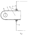
- FIG. 1 there is a total of 1 in the downpipe 1a, branch element from the intermediate member 2 with the connector 3, and the tongue 4 projecting through the connector 3.
- the connector 3 has the flange connection 5, with the aid of which the connector 3 is connected to the opening 6b, wall 6a, of the rainwater collector 6.
- the opening 4a of the tongue 4 is located concentrically with the downpipe 1a (FIG. 2).
- the opening 4a in the tongue 4 is raised in relation to the tongue material surrounding the opening 4a, so that there is a recessed bowl-shaped design for the area around the opening 4a.
- the further course of the part 4b of the tongue protruding through the nozzle into the collector is also cup-shaped.
- Below the tongue 4 is the distance 7 through which the excess water runs back from the collector 6 into the downpipe 1a.
Landscapes
- Engineering & Computer Science (AREA)
- Public Health (AREA)
- Water Supply & Treatment (AREA)
- Structural Engineering (AREA)
- Environmental & Geological Engineering (AREA)
- Health & Medical Sciences (AREA)
- Life Sciences & Earth Sciences (AREA)
- Hydrology & Water Resources (AREA)
- Architecture (AREA)
- Civil Engineering (AREA)
- Paper (AREA)
- Electric Cable Installation (AREA)
- Laying Of Electric Cables Or Lines Outside (AREA)
- Roof Covering Using Slabs Or Stiff Sheets (AREA)
- Nozzles (AREA)
- Vehicle Step Arrangements And Article Storage (AREA)
- Sewage (AREA)
- Domestic Plumbing Installations (AREA)
Abstract
Description
- Die Erfindung betrifft ein Abzweigelement zum Einsetzen in das Fallrohr einer Dachrinne, umfassend ein die Fallrohrenden erfassendes Zwischenglied, das auf seinem Mantel eine Öffnung zur Aufnahme einer Zunge zum Ableiten des Wassers in einen Regenwassersammler aufweist.
- Ein Abzweigelement der eingangs genannten Art ist bekannt. Hierbei ist die Zunge klappbar in dem Zwischenglied angeordnet, wobei bei herausgeklappter Zunge das von oben durch das Fallrohr einströmende Regenwasser beispielsweise in eine Regenwassertonne abgeleitet wird. Ist die Regenwassertonne voll, muß die Zunge eingeklappt werden, da ansonsten die Regenwassertonne ständig überläuft. D. h., es muß der Füllstand der Regenwassertonne immer beobachtet werden. Dies ist umständlich und wird daher auch nur in den seltensten Fällen gemacht; d. h., es wird immer wieder passieren, daß die Regenwassertonne überläuft und sich um die Regenwassertonne Nässe ausbreitet, die gegebenenfalls auch in die Hausmauern einzieht, da sich derartige Regenwassertonnen in unmittelbarer Nähe der Hauswand befinden.
- Der Erfindung liegt daher die Aufgabe zugrunde, ein Abzweigelement der eingangs genannten Art derart weiterzubilden, daß das Abzweigelement bei gefülltem Regenwassersammler als Überlauf fungieren kann.
- Die Aufgabe wird erfindungsgemäß dadurch gelöst, daß das Zwischenglied einen Stutzen besitzt, der in eine in der Wandung des Sammlers vorhandene Öffnung hineinragt, wobei die Zunge derart in dem Zwischenglied angeordnet ist, daß unterhalb der Zunge ein Abstand zur Innenwandung des Stutzens besteht. Hieraus folgt, daß bei gefüllter Tonne das über die Zunge zufließende Wasser unmittelbar unter der Zunge durch den Stutzen wieder in das Fallrohr zurückgeleitet wird. Die Gefahr des Überlaufs des Regenwassersammlers, bzw. der Tonne besteht demzufolge nicht mehr.
- Nach einem besonderen Merkmal der Erfindung ist vorgesehen, daß die Zunge im Bereich des Fallrohres eine konzentrisch zum Fallrohr angeordnete Öffnung besitzt, wobei der Bereich um die Öffnung vertieft schalenförmig ausgebildet ist. Es ist bekannt, daß bei geringen Wassermengen das Wasser mehr oder weniger spiralförmig an der Innenwandung des Fallrohres hinabläuft. D.h., geringe Wassermengen werden von der vertieft schalenförmigen Ausbildung der Zunge aufgenommen und in den Regenwassersammler abgeleitet. Müssen große Wassermengen durch das Fallrohr abgeführt werden, so bildet sich kein an der Innenwandung des Fallrohres entlanggleitender Wasserfilm, vielmehr stürzt das Wasser gleichsam durch das Fallrohr. In diesem Fall wird durch die Öffnung in der Zunge ein Großteil des Wassers unmittelbar weitergeleitet, d.h. nicht erst über den Umweg über die Tonne wieder in das Fallrohr zurückgeleitet.
- Die Erfindung zeichnet sich im einzelnen weiterhin dadurch aus, daß die Zunge im Bereich des Fallrohres an die Wandung anschließt, so daß bis auf die konzentrisch zum Fallrohr angeordnete Öffnung in der Zunge kein unmittelbarer Zugang zu dem darunter fortgeführten Fallrohr besteht.
- Anhand der Zeichnungen wird die Erfindung nachstehend beispielhaft näher erläutert.
- Fig. 1
- zeigt das Abzweigelement in einer Seitenansicht;
- Fig. 2
- zeigt einen Schnitt gemäß der Linie 2,2 aus Fig.1.
- Gemäß der Fig.1 besteht das insgesamt mit 1 bezeichnete, in dem Fallrohr 1a, Abzweigelement aus dem Zwischenglied 2 mit dem Stutzen 3, sowie die den Stutzen 3 durchragende Zunge 4. Der Stutzen 3 besitzt die Flanschverbindung 5, mit dessen Hilfe der Stutzen 3 mit der Öffnung 6b, Wandung 6a, des Regenwassersammlers 6 verbunden ist.
- Konzentrisch zu dem Fallrohr 1a befindet sich die Öffnung 4a der Zunge 4. (Fig.2). Die Öffnung 4a in der Zunge 4 gegenüber dem die Öffnung 4a umgebenden Zungenmaterial erhöht ausgebildet, sodaß sich eine vertiefte schalenförmige Ausbildung für den Bereich um die Öffnung 4a ergibt. Ebenfalls schalenförmig ausgebildet ist der weitere Verlauf der durch den Stutzen in den Sammler ragenden Teil 4b der Zunge. Unterhalb der Zunge 4 befindet sich der Abstand 7, durch den das überschüssige Wasser aus dem Sammler 6 in das Fallrohr 1a zurückläuft.
Claims (5)
- Abzweigelement zum Einsatz in das Fallrohr einer Dachrinne, umfassend ein die Fallrohrenden erfassendes Zwischenglied, das auf seinem Mantel eine Öffnung zur Aufnahme einer Zunge zum Ableiten des Wassers in einen Regenwassersammler aufweist,
dadurch gekenzeichnet, daß das Zwischenglied (2) einen Stutzen (3) besitzt, der in eine in der Wandung (6a) des Sammlers (6) angebrachten Öffnung (6b) hineinragt, und daß die Zunge (4) derart in dem Zwischenglied (2) angeordnet ist, daß unterhalb der Zunge (4) ein Abstand (7) zur Innenwandung des Stutzens (3) besteht. - Abzweigelement nach Anspruch 1
dadurch gekennzeichnet, daß die Zunge (4) im Bereich des Zwischenglieds (2) eine Öffnung (4a) besitzt, wobei der Bereich um die Öffnung (4a) vertieft schalenförmig ausgebildet ist. - Abzweigelement nach Anspruch 1
dadurch gekennzeichnet, daß der Stutzen (3) an der Wandung (6a) des Regenwassersammlers (6) verschraubt ist. - Abzweigelement nach Anspruch 2
dadurch gekennzeichnet, daß die Zunge im Bereich des Zwischengliedes (2) an die Wandung des Zwischengliedes anschließt. - Abzweigelement nach Anspruch 2
dadurch gekennzeichnet, daß die Öffnung (4a) der in Zunge (4) konzentrisch zum Fallrohr (1a) angeordnet ist.
Applications Claiming Priority (2)
| Application Number | Priority Date | Filing Date | Title |
|---|---|---|---|
| DE9316938U DE9316938U1 (de) | 1993-11-05 | 1993-11-05 | Abzweigelement zum Einsetzen in das Fallrohr einer Dachrinne |
| DE9316938U | 1993-11-05 |
Publications (3)
| Publication Number | Publication Date |
|---|---|
| EP0652327A2 true EP0652327A2 (de) | 1995-05-10 |
| EP0652327A3 EP0652327A3 (de) | 1996-10-09 |
| EP0652327B1 EP0652327B1 (de) | 2001-04-11 |
Family
ID=6900350
Family Applications (1)
| Application Number | Title | Priority Date | Filing Date |
|---|---|---|---|
| EP94115088A Expired - Lifetime EP0652327B1 (de) | 1993-11-05 | 1994-09-24 | Abzweigelement zum Einsetzen in das Fallrohr einer Dachrinne |
Country Status (3)
| Country | Link |
|---|---|
| EP (1) | EP0652327B1 (de) |
| AT (1) | ATE200540T1 (de) |
| DE (2) | DE9316938U1 (de) |
Families Citing this family (1)
| Publication number | Priority date | Publication date | Assignee | Title |
|---|---|---|---|---|
| DE102015103492A1 (de) | 2015-03-10 | 2016-09-15 | Ccc-Schilling Gmbh | Fallrohrflanschaufsatz |
Citations (4)
| Publication number | Priority date | Publication date | Assignee | Title |
|---|---|---|---|---|
| DE2747008A1 (de) | 1976-10-20 | 1978-04-27 | Insulators Ltd | Ablenkvorrichtung fuer fallrohre |
| DE2842889A1 (de) | 1978-10-02 | 1980-04-17 | Erhard Dr Baur | Einrichtung zur gewinnung von brauch- und trinkwasser aus der atmosphaere |
| GB1573321A (en) | 1977-08-10 | 1980-08-20 | Eke D | Methods and apparatus for controlling the flow of liquids |
| GB2230071A (en) | 1989-04-07 | 1990-10-10 | David Alan Rafferty | Pipe connector |
Family Cites Families (8)
| Publication number | Priority date | Publication date | Assignee | Title |
|---|---|---|---|---|
| DE7111976U (de) * | 1900-01-01 | Werlich W | ||
| DE7633124U1 (de) * | 1976-10-22 | 1977-03-03 | Zeuna-Staerker Kg, 8900 Augsburg | Einrichtung zur regenwasserabzweigung an einem regenrohr |
| DE3105744A1 (de) * | 1981-02-17 | 1982-09-23 | Harald 8581 Ramsenthal Schardt | Regenwasserentnahmestutzen am regenfallrohr |
| DE3346693C2 (de) * | 1983-12-23 | 1986-08-14 | Georg 7404 Ofterdingen Speidel | Regenwasser-Fallrohrzwischenstück |
| DE3537609A1 (de) * | 1985-08-03 | 1987-02-12 | Hess Paul | Abzweigung zwischen einer im wesentlichen vertikal verlaufenden abflussleitung und einem auffangbehaelter |
| DE3943040A1 (de) * | 1989-12-27 | 1991-07-11 | Beckmann Gerhard Kg | Regenwasser-sammler |
| GB9020868D0 (en) * | 1990-09-25 | 1990-11-07 | Embley Norman W | Water saving device |
| DE4204628A1 (de) * | 1992-02-15 | 1992-09-10 | Hemmerich Gmbh | Vorrichtung zum ableiten von regenwasser aus einem regenwasserfallrohr |
-
1993
- 1993-11-05 DE DE9316938U patent/DE9316938U1/de not_active Expired - Lifetime
-
1994
- 1994-09-24 EP EP94115088A patent/EP0652327B1/de not_active Expired - Lifetime
- 1994-09-24 AT AT94115088T patent/ATE200540T1/de not_active IP Right Cessation
- 1994-09-24 DE DE59409722T patent/DE59409722D1/de not_active Expired - Fee Related
Patent Citations (4)
| Publication number | Priority date | Publication date | Assignee | Title |
|---|---|---|---|---|
| DE2747008A1 (de) | 1976-10-20 | 1978-04-27 | Insulators Ltd | Ablenkvorrichtung fuer fallrohre |
| GB1573321A (en) | 1977-08-10 | 1980-08-20 | Eke D | Methods and apparatus for controlling the flow of liquids |
| DE2842889A1 (de) | 1978-10-02 | 1980-04-17 | Erhard Dr Baur | Einrichtung zur gewinnung von brauch- und trinkwasser aus der atmosphaere |
| GB2230071A (en) | 1989-04-07 | 1990-10-10 | David Alan Rafferty | Pipe connector |
Also Published As
| Publication number | Publication date |
|---|---|
| EP0652327B1 (de) | 2001-04-11 |
| DE9316938U1 (de) | 1994-01-13 |
| DE59409722D1 (de) | 2001-05-17 |
| EP0652327A3 (de) | 1996-10-09 |
| ATE200540T1 (de) | 2001-04-15 |
Similar Documents
| Publication | Publication Date | Title |
|---|---|---|
| DE19545361A1 (de) | Rohrverbindung mit Fitting | |
| DE69027984T2 (de) | Rinnensystem | |
| EP0652327A2 (de) | Abzweigelement zum Einsetzen in das Fallrohr einer Dachrinne | |
| DE3209058A1 (de) | Vorrichtung an abwasser-geruchsverschluessen | |
| DE3105744A1 (de) | Regenwasserentnahmestutzen am regenfallrohr | |
| DE29711053U1 (de) | Vorrichtung zur Dachentwässerung, insbesondere Dachrinne mit Fallrohr und/oder Rinneneisen | |
| DE4335545A1 (de) | Lichtkuppel | |
| DE19651785B4 (de) | Pultdach-Abschlußziegel | |
| DE29904139U1 (de) | Ablaufgarnitur für eine Badewanne | |
| DE3114479C2 (de) | Zerlegbares Zeltgerüst aus Leichtmetall | |
| DE3404665A1 (de) | Haustuervordach | |
| EP4411699A1 (de) | Grabkerze | |
| EP1008881A1 (de) | Knickschutzvorrichtung für Lichtwellenleiterkabel | |
| DE8909323U1 (de) | Vorrichtung zum Ableiten von Regenwasser aus einem Wasserabflußrohr | |
| DE7417587U (de) | Haustuervordach | |
| EP0332051B1 (de) | Ablauf für Überlaufrinnen von Schwimmbädern | |
| DE8709796U1 (de) | Dachentwässerung | |
| DE8523782U1 (de) | Fitting | |
| DE29515024U1 (de) | Rohrverbindungsstück zum Verbinden von ungemufften Rohren | |
| EP3524749A1 (de) | Klemmfeder zur verbindung von entwässerungskomponenten, insbesondere dachentwässerungskomponenten | |
| DE7533207U (de) | Vorrichtung fuer flachdaecher zur be- und entlueftung von abwasserleitungen | |
| DE29722568U1 (de) | Regenfallrohr mit einem im Innern angebrachten Sieb | |
| DE8521522U1 (de) | Gelenkelement für Rohre od.dgl. | |
| DE7149005U (de) | Grundplatte von vorschaltgeraeten fuer leuchtstofflampen | |
| DE8815001U1 (de) | Versorgungsrinne |
Legal Events
| Date | Code | Title | Description |
|---|---|---|---|
| PUAI | Public reference made under article 153(3) epc to a published international application that has entered the european phase |
Free format text: ORIGINAL CODE: 0009012 |
|
| AK | Designated contracting states |
Kind code of ref document: A2 Designated state(s): AT BE CH DE DK FR IT LI NL SE |
|
| PUAL | Search report despatched |
Free format text: ORIGINAL CODE: 0009013 |
|
| AK | Designated contracting states |
Kind code of ref document: A3 Designated state(s): AT BE CH DE DK FR IT LI NL SE |
|
| 17P | Request for examination filed |
Effective date: 19961014 |
|
| 17Q | First examination report despatched |
Effective date: 19981006 |
|
| GRAG | Despatch of communication of intention to grant |
Free format text: ORIGINAL CODE: EPIDOS AGRA |
|
| GRAG | Despatch of communication of intention to grant |
Free format text: ORIGINAL CODE: EPIDOS AGRA |
|
| GRAG | Despatch of communication of intention to grant |
Free format text: ORIGINAL CODE: EPIDOS AGRA |
|
| GRAH | Despatch of communication of intention to grant a patent |
Free format text: ORIGINAL CODE: EPIDOS IGRA |
|
| GRAH | Despatch of communication of intention to grant a patent |
Free format text: ORIGINAL CODE: EPIDOS IGRA |
|
| GRAH | Despatch of communication of intention to grant a patent |
Free format text: ORIGINAL CODE: EPIDOS IGRA |
|
| GRAA | (expected) grant |
Free format text: ORIGINAL CODE: 0009210 |
|
| AK | Designated contracting states |
Kind code of ref document: B1 Designated state(s): AT BE CH DE DK FR IT LI NL SE |
|
| PG25 | Lapsed in a contracting state [announced via postgrant information from national office to epo] |
Ref country code: NL Free format text: LAPSE BECAUSE OF FAILURE TO SUBMIT A TRANSLATION OF THE DESCRIPTION OR TO PAY THE FEE WITHIN THE PRESCRIBED TIME-LIMIT Effective date: 20010411 Ref country code: IT Free format text: LAPSE BECAUSE OF FAILURE TO SUBMIT A TRANSLATION OF THE DESCRIPTION OR TO PAY THE FEE WITHIN THE PRESCRIBED TIME-LIMIT;WARNING: LAPSES OF ITALIAN PATENTS WITH EFFECTIVE DATE BEFORE 2007 MAY HAVE OCCURRED AT ANY TIME BEFORE 2007. THE CORRECT EFFECTIVE DATE MAY BE DIFFERENT FROM THE ONE RECORDED. Effective date: 20010411 Ref country code: FR Free format text: LAPSE BECAUSE OF FAILURE TO SUBMIT A TRANSLATION OF THE DESCRIPTION OR TO PAY THE FEE WITHIN THE PRESCRIBED TIME-LIMIT Effective date: 20010411 |
|
| REF | Corresponds to: |
Ref document number: 200540 Country of ref document: AT Date of ref document: 20010415 Kind code of ref document: T |
|
| REG | Reference to a national code |
Ref country code: CH Ref legal event code: EP |
|
| REF | Corresponds to: |
Ref document number: 59409722 Country of ref document: DE Date of ref document: 20010517 |
|
| PG25 | Lapsed in a contracting state [announced via postgrant information from national office to epo] |
Ref country code: SE Free format text: LAPSE BECAUSE OF FAILURE TO SUBMIT A TRANSLATION OF THE DESCRIPTION OR TO PAY THE FEE WITHIN THE PRESCRIBED TIME-LIMIT Effective date: 20010711 Ref country code: DK Free format text: LAPSE BECAUSE OF FAILURE TO SUBMIT A TRANSLATION OF THE DESCRIPTION OR TO PAY THE FEE WITHIN THE PRESCRIBED TIME-LIMIT Effective date: 20010711 |
|
| NLV1 | Nl: lapsed or annulled due to failure to fulfill the requirements of art. 29p and 29m of the patents act | ||
| EN | Fr: translation not filed | ||
| PG25 | Lapsed in a contracting state [announced via postgrant information from national office to epo] |
Ref country code: AT Free format text: LAPSE BECAUSE OF NON-PAYMENT OF DUE FEES Effective date: 20010924 |
|
| PG25 | Lapsed in a contracting state [announced via postgrant information from national office to epo] |
Ref country code: LI Free format text: LAPSE BECAUSE OF NON-PAYMENT OF DUE FEES Effective date: 20010930 Ref country code: CH Free format text: LAPSE BECAUSE OF NON-PAYMENT OF DUE FEES Effective date: 20010930 Ref country code: BE Free format text: LAPSE BECAUSE OF NON-PAYMENT OF DUE FEES Effective date: 20010930 |
|
| PLBE | No opposition filed within time limit |
Free format text: ORIGINAL CODE: 0009261 |
|
| STAA | Information on the status of an ep patent application or granted ep patent |
Free format text: STATUS: NO OPPOSITION FILED WITHIN TIME LIMIT |
|
| BERE | Be: lapsed |
Owner name: SCHNEIDER FRITZ Effective date: 20010930 |
|
| 26N | No opposition filed | ||
| REG | Reference to a national code |
Ref country code: CH Ref legal event code: PL |
|
| PGFP | Annual fee paid to national office [announced via postgrant information from national office to epo] |
Ref country code: DE Payment date: 20050916 Year of fee payment: 12 |
|
| PG25 | Lapsed in a contracting state [announced via postgrant information from national office to epo] |
Ref country code: DE Free format text: LAPSE BECAUSE OF NON-PAYMENT OF DUE FEES Effective date: 20070403 |