EP0652563B1 - Cassette à disque - Google Patents
Cassette à disque Download PDFInfo
- Publication number
- EP0652563B1 EP0652563B1 EP95100147A EP95100147A EP0652563B1 EP 0652563 B1 EP0652563 B1 EP 0652563B1 EP 95100147 A EP95100147 A EP 95100147A EP 95100147 A EP95100147 A EP 95100147A EP 0652563 B1 EP0652563 B1 EP 0652563B1
- Authority
- EP
- European Patent Office
- Prior art keywords
- disc cartridge
- extension portion
- shutter
- slider
- extending
- Prior art date
- Legal status (The legal status is an assumption and is not a legal conclusion. Google has not performed a legal analysis and makes no representation as to the accuracy of the status listed.)
- Expired - Lifetime
Links
- 230000037431 insertion Effects 0.000 claims description 14
- 238000003780 insertion Methods 0.000 claims description 14
- 230000003287 optical effect Effects 0.000 description 3
- 230000015572 biosynthetic process Effects 0.000 description 1
- 230000006835 compression Effects 0.000 description 1
- 238000007906 compression Methods 0.000 description 1
- 239000002184 metal Substances 0.000 description 1
- 230000002093 peripheral effect Effects 0.000 description 1
- 230000000717 retained effect Effects 0.000 description 1
Images


Classifications
-
- G—PHYSICS
- G11—INFORMATION STORAGE
- G11B—INFORMATION STORAGE BASED ON RELATIVE MOVEMENT BETWEEN RECORD CARRIER AND TRANSDUCER
- G11B23/00—Record carriers not specific to the method of recording or reproducing; Accessories, e.g. containers, specially adapted for co-operation with the recording or reproducing apparatus ; Intermediate mediums; Apparatus or processes specially adapted for their manufacture
- G11B23/02—Containers; Storing means both adapted to cooperate with the recording or reproducing means
- G11B23/03—Containers for flat record carriers
- G11B23/0301—Details
- G11B23/031—Indicating means, e.g. sticker, bar code
-
- G—PHYSICS
- G11—INFORMATION STORAGE
- G11B—INFORMATION STORAGE BASED ON RELATIVE MOVEMENT BETWEEN RECORD CARRIER AND TRANSDUCER
- G11B17/00—Guiding record carriers not specifically of filamentary or web form, or of supports therefor
- G11B17/02—Details
- G11B17/04—Feeding or guiding single record carrier to or from transducer unit
- G11B17/041—Feeding or guiding single record carrier to or from transducer unit specially adapted for discs contained within cartridges
- G11B17/043—Direct insertion, i.e. without external loading means
- G11B17/0436—Direct insertion, i.e. without external loading means with opening mechanism of the cartridge shutter
-
- G—PHYSICS
- G11—INFORMATION STORAGE
- G11B—INFORMATION STORAGE BASED ON RELATIVE MOVEMENT BETWEEN RECORD CARRIER AND TRANSDUCER
- G11B23/00—Record carriers not specific to the method of recording or reproducing; Accessories, e.g. containers, specially adapted for co-operation with the recording or reproducing apparatus ; Intermediate mediums; Apparatus or processes specially adapted for their manufacture
- G11B23/02—Containers; Storing means both adapted to cooperate with the recording or reproducing means
- G11B23/03—Containers for flat record carriers
- G11B23/0301—Details
- G11B23/0302—Auxiliary features
- G11B23/0303—Write protect features with a sliding part
-
- G—PHYSICS
- G11—INFORMATION STORAGE
- G11B—INFORMATION STORAGE BASED ON RELATIVE MOVEMENT BETWEEN RECORD CARRIER AND TRANSDUCER
- G11B23/00—Record carriers not specific to the method of recording or reproducing; Accessories, e.g. containers, specially adapted for co-operation with the recording or reproducing apparatus ; Intermediate mediums; Apparatus or processes specially adapted for their manufacture
- G11B23/02—Containers; Storing means both adapted to cooperate with the recording or reproducing means
- G11B23/03—Containers for flat record carriers
- G11B23/0301—Details
- G11B23/0308—Shutters
Definitions
- the present invention relates to a disc cartridge according to the preamble of claim 1.
- a magnetic disc or an optical disc is encased in a cassette case made of two shell halves.
- a hole into which a spindle for rotating the disc is to be inserted is formed in a central portion of the cassette case.
- Head insertion holes into which a write and read head is to be inserted is formed in the cassette case so as to extend in the radial direction to traverse the recording surface of the disc.
- Such a disc cartridge is shown in, for example, Japanese Utility Model Unexamined Publication No. 62-168176.
- This cartridge has a shell for encasing the disc.
- a spindle hole is formed in the central portion of the shell half.
- a hub formed in the central portion of the disc is located in the spindle hole of each shell half.
- the spindle of the recording and reproducing apparatus is to be located at the hub which is sucked by a turntable.
- the head insertion holes are formed on an insertion side of the cartridge relative to the recording and reproducing apparatus.
- a write and read head (pickup head) is inserted into one of the head insertion holes.
- the head insertion holes are closed and opened by sliding movement of the shutter.
- the shutter is bent at its intermediate portion so as to extend to the top and bottom of the cartridge to cover the head insertion holes and two spindle holes.
- the shutter On the insertion side of the cartridge into the recording and reproducing apparatus, the shutter is slidingly moved along a guide portion of the cartridge front edge to open and close the insertion holes and the spindle holes.
- EP 0 255 185 A1 discloses a disc cassette comprising an enclosure and a shutter which is uniformly and easily movable and which can easily be mounted on the enclosure. This is achieved by rigidly connecting the shutter to a slide 11 which is slidably connected to the enclosure by parallel guide means.
- This document further discloses an omega type spring which acts on the slide.
- This spring has a first straight arm connected to the tip end of the slide, and a second arm comprising a first extension portion extending substantially tangentially from the coil portion of the spring, and a second portion bent from the first extension portion, an a distal end connected to the front edge of the disc cartridge.
- a cartridge C for an optical disc has a cartridge case 1 which is composed of upper and lower shell halves 2 and 3 in alignment with each other.
- a spindle hole 4 is formed in the central portion of the case 1, the spindle hole 4 being integrally formed with a head insertion hole 5.
- a lower end of the shutter 6 is guided by a retainer plate 6.
- Double writing preventing portions 9a and 9b are provided on the right and left sides on the rear edge side in the insertion direction to the recording and reproducing apparatus for the cartridge C.
- a shutter 6 is bent at the front edge of the case 1 to extend to the bottom side.
- a return coil spring 10 is encased on the left side of the case 1, so that the shutter 6 is biased in the direction to close the holes 4 and 5.
- the shutter plate 6 is formed of a single metal sheet such as a stainless plate as shown in Fig. 2.
- a shutter 6 is provided with two planar plates 11, 11 confronted with each other and a head portion 13 defined by a connecting portion of the planar plates 11, 11.
- a slide portion is formed in a lower portion of each planar plate 11 so as to slidingly engage with the retainer plate 8.
- the head portion 13 is fixed by screws 15, 15 for covering an elongated slider 14.
- the screws 15, 15 are threadedly engaged with receiving holes 18, 18 of the slider 14 through openings 18, 18.
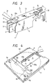
- An opening and closing pin receiving hole 17 into which an opening and closing pin P1 is formed on a drive side of the recording and reproducing apparatus is inserted is formed in a tail portion of the head portion 13 (Fig. 3).
- a receiving recess 19 is formed in the slider 14 corresponding to the opening and closing pin receiving hole 17.
- the opening and closing pin P1 mounted on an arm 30 as shown in Fig. 3 is engaged with the receiving recess 19.
- Guide grooves 21, 21 are formed in both sides of the slider 14 and are adapted to engage with guide rails 22, 22 (Fig. 2) formed in a guide portion G formed at a front edge of the cartridge C on the recording and reproducing side as shown in Fig. 3.
- a slanted surface 20 is formed at a front face of the slider 14.
- the slanted surface 20 serves to assist a smooth passage of an opening and closing pin P2 mounted on an arm 31 on the drive side of the recording and reproducing apparatus as shown in Fig. 3.
- one of the opening and closing pins P1 and P2 is inserted into the receiving recess 19 of the slider 14 and the receiving hole 17 of the shutter 6.
- the opening and closing pin P1 moves the shutter 6 leftwardly to open the spindle holes 4 and the head insertion holes 5 as shown in Fig. 4
- the other opening and closing pin P2 rides over and along the slanted surface 20 of the slider 14 so that the pins P1 and P2 cross with each other.
- pins P1 and P2 cross with each other.
- a so-called disposal pin i.e., the unnecessary opening and closing pin P2 is smoothly guided.
- the slider 14 is engaged with the guide portion G at the front edge of the cartridge C on the recording and reproducing apparatus side, and the shutter 6 is held to the slider 14. Therefore, when the shutter 6 is frequently moved by the opening and closing pin P1 for the opening and closing operation, the slider 14 made of plastic is engaged with a guide portion G made of plastic, so that any cut chips will not be generated by the sliding contact therebetween. Thus, there is no fear that the disc would be contaminated. Also, even if the cartridge C is protect the shutter 6. Thus, the shutter 6 is prevented effectively from being separated apart from the cartridge.
- a recess 30' As shown in Fig. 5.
- a slanted surface 30a is formed in an inner side of the recess 30'.
- a distal end 10a of the coil spring 10 is retained in a receiving portion 33 on the inner side of the slanted surface 30a.
- the distal end 10a of the coil spring 10 is received on the slanted surface 30a through a cutout 32 formed in a planar portion 31' of the slider 14.
- a projection 31a is formed on an inner surface of the planar portion 31' and the distal end 10a of the coil spring 10 extends through the cutout 32.
- the projection 31a has a slanted surface So.
- the projection 31a serves to smoothly guide the distal end 10a into a receiving portion 33a and simultaneously to retain the distal end 10a at the receiving portion 33a against the collision transmitted from the outside.
- a receiving space S for the return coil spring 10 is substantially in the form of a rectangular shape.
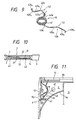
- the coil spring 10 is composed of a coiled elastic portion 41, and two arms 42 and 43 extending laterally from the coiled portion 41.
- the arm 43 is composed of a first extension portion 43a extending substantially along a peripheral wall W1 formed around a circumferential edge of the optical disc (not shown) in the case 1, and a second extension portion 43b extending from the first extension portion 43a along the front edge wall W2 of the cartridge.
- the second extension portion 43b is composed of a longitudinal portion 43b1, a laterally extending portion 43b2 bent from the portion 43b1 in the horizontal direction, and a retainer portion 43b3 engaged with an end portion of the slider 14 and bent at a right angle from the laterally extending portion 43b2 for guiding the shutter 6.
- the arm 42 is composed of a third extension portion 42a extending toward the front wall of the cartridge from the coiled portion 41, and a fourth extension portion 42b extending generally in the lateral direction from the third extension portion 42a.
- the fourth extension portion 42b is composed of crest-shape forming portions 42b1 and 42b2 for forming the crest shape on the left side in Fig. 9 extended from the third extension portion 42a, a jump portion 42b3 extending toward the front wall W2 of the cartridge from the crest-shape forming portion 42b2, and a retainer portion 42b4 extended from the jump portion 42b3 and curved at a right angle for engaging with a end wall W3 of the cartridge.
- Fig. 10 is a view as viewed in the direction indicated by the arrow A in Fig. 8.
- the slider 14 is moved along the guide rails 22, 22 of the halves 2, 3.
- An opening 0 is formed in a front face of the upper and lower halves 2 and 3.
- the coil spring 10 is inserted from the opening 0 while the one end of the spring 10 is being engaged with the side wall W3 by the end of the slider 14 in the final step of the assembling operation.
- receiving portions 33, 33b for detachably receiving the spring retainer portions 42b4 and 43b3 are formed in the slider end portion and the side wall W3, respectively.
- the central portion of the coiled portion 41 of the spring 10 is reciprocatingly moved along a locus B.
- the coiled portion 41 is moved along the circumferential wall W1 without colliding against the latter W1.
- the arms 42 and 43 are bent as described above, the coiled portion 41 is swayed in the lateral direction in accordance with the leftward movement of the slider 14, so that the reduction in opening angle óo (see Fig. 8) defined by the arms 42 and 43 may be kept at a low level even if the distance of the lateral movement of the slide 14 is increased.
- the return spring 10 is structured as described above, even if the receiving space S for the return coil spring is small, it is possible to increase the movement range of the shutter, thereby making the cartridge more compact and ensuring the smooth and large opening and closing operation of the shutter.
- a radius r at the bent portion between the crest shaped portion 42b1 and the third extension portion 4a be in the range of 0.8 to 3 mm.
- the coil spring 10 could function normally after repeated opening and closing operations of the shutter over 100,000 times. If the radius r would be too small, the durability would be lowered, whereas if the radius r would be too large, the movement during the expansion and compression of the spring would be changed according to every spring. In the latter case, it would be difficult to control the spring property in a prescribed manner.
Landscapes
- Feeding And Guiding Record Carriers (AREA)
Claims (5)
- Cartouche de disque destinée à renfermer un disque formant moyen d'enregistrement, ladite cartouche de disque comprenant un bord avant destiné à être inséré dans un appareil d'enregistrement ou de reproduction ;un obturateur (6) monté de manière coulissante sur ladite cartouche de disque pour ouvrir et fermer au moins un orifice d'insertion de tête (5) formé dans ladite cartouche de disque, ledit obturateur (6) comprenant une partie formant tête (13) pouvant être déplacée de manière coulissante le long dudit bord avant de ladite cartouche de disque, ladite partie formant tête ayant des parties plates d'ouverture et de fermeture (11) s'étendant depuis ses deux côtés ;une partie de guidage (G) formée dans ledit bord avant de ladite cartouche de disque ;un coulisseau (14) guidée de manière coulissante à l'intérieur de ladite partie de guidage (G) pour supporter ledit obturateur ; etun ressort à boudin de rappel (10) pour solliciter l'obturateur (6) à travers ledit coulisseau pour l'amener dans une position dans laquelle ledit obturateur ferme ledit orifice d'insertion de tête (5) ;dans laquelle ledit ressort à boudin de rappel (10) est composé d'une partie enroulée de fil métallique élastique (41) munie de deux bras (42, 43) s'étendant à partir de celle-ci et est positionné à l'intérieur d'un coin de la cartouche de disque ; et
dans laquellel'un desdits bras (43) est composé d'une première partie d'extension (43a) s'étendant sensiblement de manière tangentielle de ladite partie enroulée (41) et d'une deuxième partie d'extension (43b) incurvée à partir de ladite première partie d'extension ;ladite deuxième partie d'extension (43b) comprend une partie d'extension longitudinale (43b1), une partie d'extension latérale (43b2) repliée à partir de ladite partie d'extension longitudinale et une première partie de retenue (43b3) incurvée à angle droit à partir de ladite partie d'extension latérale et étant reliée à l'extrémité de bout de l'obturateur (14) ; etl'autre bras (42) est composé d'une troisième partie d'extension (42a) s'étendant de manière tangentielle à partir de ladite partie enroulée (41) et d'une quatrième partie d'extension (42b) incurvée à partir de ladite troisième partie d'extension, dans lequel la quatrième partie d'extension comprend une extrémité distale qui est reliée au bord avant de ladite cartouche de disque. - Cartouche de disque selon la revendication 1, caractérisée en ce que le rayon (r) de courbure d'une partie incurvée entre ladite troisième partie d'extension (42a) et ladite quatrième partie d'extension (42b) est compris dans une plage allant de 0,8 à 3 mm.
- Cartouche de disque selon la revendication 1 ou 2, caractérisée en ce que ladite quatrième partie d'extension (42b) forme une crête trapézoïdale avec la troisième partie d'extension (42a) et comprend :une partie de détente (42b3) s'étendant à partir de l'extrémité distale de la forme de crête trapézoïdale, etune deuxième partie de retenue (42b4) étant incurvée à angle droit pour être reliée avec le bord avant de la cartouche de disque, dans laquelle ladite deuxième partie de retenue s'étend dans une direction opposée à la direction de ladite première partie de retenue (43b3) de la deuxième partie d'extension.
- Cartouche de disque selon l'une quelconque des revendications 1 à 3, caractérisée en ce que l'extrémité de bout de l'obturateur a la forme d'un avant-toit (20) ;une rainure de guidage (30') est formée sur la surface inférieure de l'avant-toit et comprend une surface inclinée (30a) pour guider une extrémité distale (10a) d'un bras du ressort à boudin de rappel (10) vers une partie réceptrice (33) qui est située dans une position en retrait par rapport à l'extrémité avant de l'avant-toit ; etl'extrémité distale (10a) est reçue dans une partie formant creux (33a) formée à l'intérieur de la partie réceptrice (33) après avoir été guidée à travers une échancrure (32) qui est formée sur la paroi inférieure de l'obturateur (14).
- Cartouche de disque selon la revendication 4, caractérisée en ce qu'une saillie (31a) est prévue le long de l'échancrure (32) dans la partie réceptrice (33) pour guider l'extrémité distale du ressort à boudin de rappel (10) dans la partie formant creux (33a) et pour éviter que l'extrémité distale, une fois introduite dans la partie formant creux, ne sorte de celle-ci.
Applications Claiming Priority (16)
| Application Number | Priority Date | Filing Date | Title |
|---|---|---|---|
| JP5676688U | 1988-04-28 | ||
| JP5676788U | 1988-04-28 | ||
| JP1988056772U JP2524898Y2 (ja) | 1988-04-28 | 1988-04-28 | ディスクカートリッジのシャッタ |
| JP5676888U | 1988-04-28 | ||
| JP5676688U JPH0617229Y2 (ja) | 1988-04-28 | 1988-04-28 | ディスクカートリッジ |
| JP56772/88U | 1988-04-28 | ||
| JP56767/88U | 1988-04-28 | ||
| JP56766/88U | 1988-04-28 | ||
| JP1988056767U JPH0734549Y2 (ja) | 1988-04-28 | 1988-04-28 | ディスクカートリッジ |
| JP1988056768U JP2535923Y2 (ja) | 1988-04-28 | 1988-04-28 | ディスクカートリッジ |
| JP5677288U | 1988-04-28 | ||
| JP56768/88U | 1988-04-28 | ||
| JP85101/88U | 1988-06-29 | ||
| JP8510188U | 1988-06-29 | ||
| JP1988085101U JPH0739101Y2 (ja) | 1988-06-29 | 1988-06-29 | ディスクカートリッジのシャッタとスライダの固定構造 |
| EP89107687A EP0339651B1 (fr) | 1988-04-28 | 1989-04-27 | Cartouche de disque |
Related Parent Applications (2)
| Application Number | Title | Priority Date | Filing Date |
|---|---|---|---|
| EP89107687A Division EP0339651B1 (fr) | 1988-04-28 | 1989-04-27 | Cartouche de disque |
| EP89107687.9 Division | 1989-04-27 |
Publications (3)
| Publication Number | Publication Date |
|---|---|
| EP0652563A2 EP0652563A2 (fr) | 1995-05-10 |
| EP0652563A3 EP0652563A3 (fr) | 1996-02-07 |
| EP0652563B1 true EP0652563B1 (fr) | 2001-09-26 |
Family
ID=27523319
Family Applications (3)
| Application Number | Title | Priority Date | Filing Date |
|---|---|---|---|
| EP89107687A Expired - Lifetime EP0339651B1 (fr) | 1988-04-28 | 1989-04-27 | Cartouche de disque |
| EP95100146A Expired - Lifetime EP0650165B1 (fr) | 1988-04-28 | 1989-04-27 | Cassette à disque |
| EP95100147A Expired - Lifetime EP0652563B1 (fr) | 1988-04-28 | 1989-04-27 | Cassette à disque |
Family Applications Before (2)
| Application Number | Title | Priority Date | Filing Date |
|---|---|---|---|
| EP89107687A Expired - Lifetime EP0339651B1 (fr) | 1988-04-28 | 1989-04-27 | Cartouche de disque |
| EP95100146A Expired - Lifetime EP0650165B1 (fr) | 1988-04-28 | 1989-04-27 | Cassette à disque |
Country Status (3)
| Country | Link |
|---|---|
| US (2) | US5408458A (fr) |
| EP (3) | EP0339651B1 (fr) |
| DE (3) | DE68929326T2 (fr) |
Families Citing this family (25)
| Publication number | Priority date | Publication date | Assignee | Title |
|---|---|---|---|---|
| DE68929173T2 (de) * | 1988-06-29 | 2000-07-13 | Dai Nippon Insatsu K.K., Tokio/Tokyo | Plattenkassette |
| JP2770394B2 (ja) * | 1989-04-06 | 1998-07-02 | ソニー株式会社 | ディスクカートリッジ |
| US5158640A (en) * | 1989-06-13 | 1992-10-27 | Dai Nippon Insatsu K.K. | Apparatus for and method of applying part onto cartridge |
| US5166922A (en) * | 1990-01-29 | 1992-11-24 | Dai Nippon Insatsu Kabushiki Kaisha | Disk cartridge |
| KR100252370B1 (ko) * | 1990-02-14 | 2000-04-15 | 기타지마 요시토시 | 3.5인치용의디스크카트리지 |
| JPH0438689A (ja) * | 1990-05-31 | 1992-02-07 | Sony Corp | ディスクカートリッジ |
| JP2961982B2 (ja) * | 1990-08-24 | 1999-10-12 | ソニー株式会社 | ディスクカートリッジ |
| AT394788B (de) * | 1990-10-11 | 1992-06-25 | Philips Nv | Kassette fuer einen aufzeichnungstraeger |
| JP3296375B2 (ja) * | 1993-07-13 | 2002-06-24 | 株式会社東芝 | ディスクカートリッジ装置 |
| DE69509270T2 (de) * | 1994-01-28 | 1999-11-04 | Sony Corp., Tokio/Tokyo | Plattenkassette |
| EP0667616B1 (fr) * | 1994-02-15 | 2006-07-19 | Mitsubishi Chemical Corporation | Cassette à disque |
| US5691868A (en) * | 1994-04-07 | 1997-11-25 | Sony Corporation | Disk cartridge with shutter and slider, and method of connecting them |
| JP2898886B2 (ja) * | 1994-09-20 | 1999-06-02 | 松下電器産業株式会社 | ディスクカートリッジ |
| JPH08306152A (ja) * | 1995-04-28 | 1996-11-22 | Toshiba Corp | ディスクカ−トリッジ |
| JPH08306149A (ja) * | 1995-04-28 | 1996-11-22 | Minnesota Mining & Mfg Co <3M> | 改良型シャッタ機構を備えたデータ記憶ディスケット |
| EP0766249A3 (fr) * | 1995-09-29 | 1997-09-24 | Dainippon Printing Co Ltd | Cassette à disque |
| US6094326A (en) * | 1996-08-20 | 2000-07-25 | Tdk Corporation | Disc cartridge with improved shutter mechanism |
| JPH1145539A (ja) * | 1997-07-29 | 1999-02-16 | Tdk Corp | ディスクカートリッジ |
| US6201250B1 (en) | 1997-08-22 | 2001-03-13 | Richard C. Morlock | Sensor housing for UV curing chamber |
| US6687215B1 (en) | 2000-04-12 | 2004-02-03 | Dphi Acquisitions, Inc. | Low profile and medium protecting cartridge assembly |
| TW554337B (en) * | 2000-04-12 | 2003-09-21 | Dataplay Inc | Low profile cartridge for data storage disk |
| EP1388860A4 (fr) * | 2001-05-11 | 2006-12-13 | Sony Corp | Cartouche de support d'enregistrement d'informations |
| JP2005222671A (ja) * | 2004-01-08 | 2005-08-18 | Sony Corp | ディスクカートリッジ |
| EP1796093A4 (fr) * | 2004-09-28 | 2008-05-07 | Matsushita Electric Industrial Co Ltd | Cartouche de disque |
| JP4686302B2 (ja) * | 2005-08-23 | 2011-05-25 | 富士フイルム株式会社 | 感光性記録媒体用カートリッジ及びその製造方法 |
Family Cites Families (31)
| Publication number | Priority date | Publication date | Assignee | Title |
|---|---|---|---|---|
| JPS57154685A (en) * | 1981-03-19 | 1982-09-24 | Hitachi Maxell Ltd | Assembling method of magnetic tape cartridge |
| JPS5870463A (ja) * | 1981-10-21 | 1983-04-26 | Hitachi Ltd | デイスクカセツト |
| JPS59177073U (ja) * | 1983-05-13 | 1984-11-27 | ソニー株式会社 | ディスクカセット |
| CA1241740A (fr) * | 1984-04-28 | 1988-09-06 | Kokichi Sugawara | Cassette de disque magnetique souple |
| JPH0627029Y2 (ja) * | 1984-06-01 | 1994-07-20 | 富士写真フイルム株式会社 | 磁気ディスクカートリッジ |
| JPS6168782A (ja) * | 1984-09-12 | 1986-04-09 | Sony Corp | デイスクカ−トリツジ |
| JPH0424536Y2 (fr) * | 1985-04-15 | 1992-06-10 | ||
| JPS61258381A (ja) * | 1985-05-11 | 1986-11-15 | Hitachi Maxell Ltd | デイスクカ−トリツジ |
| JPS6282579A (ja) * | 1985-10-07 | 1987-04-16 | Hitachi Maxell Ltd | デイスクカ−トリツジ |
| JPS6290448U (fr) * | 1985-11-22 | 1987-06-10 | ||
| JPS62143273A (ja) * | 1985-12-17 | 1987-06-26 | Mitsubishi Electric Corp | デイスクカ−トリツジ |
| JPH0740423B2 (ja) * | 1986-03-01 | 1995-05-01 | 日立マクセル株式会社 | デイスクカ−トリツジ |
| JPS62217478A (ja) * | 1986-03-18 | 1987-09-24 | Mitsubishi Electric Corp | 円板状情報記録媒体用カセツト |
| JPS62168176U (fr) | 1986-04-11 | 1987-10-24 | ||
| JPH0682504B2 (ja) * | 1986-04-30 | 1994-10-19 | ソニー株式会社 | デイスクカ−トリツジ |
| US5196978A (en) * | 1986-05-27 | 1993-03-23 | Sharp Kabushiki Kaisha | Cartridge case |
| IT1203575B (it) * | 1986-06-20 | 1989-02-15 | Olivetti & Co Spa | Cartuccia per un disco ottico di registrazione di dati sulle due facce e relativo dispositivo di lettura |
| EP0273983B1 (fr) * | 1986-07-04 | 1992-03-11 | Sony Corporation | Chargeur de disques |
| NL8601884A (nl) * | 1986-07-21 | 1988-02-16 | Philips Nv | Plaatcassette. |
| NL8601944A (nl) * | 1986-07-29 | 1988-02-16 | Optical Storage Int | Schijfcassette omvattende een informatieschijf. |
| JPS6361484A (ja) * | 1986-09-01 | 1988-03-17 | Toshiba Corp | 情報記憶媒体用カ−トリツジ |
| JPS6396784A (ja) * | 1986-10-13 | 1988-04-27 | Hitachi Maxell Ltd | デイスクカ−トリツジ |
| US4908817A (en) * | 1986-11-14 | 1990-03-13 | Opticord, Inc. | Cartridge for optical data discs |
| JPH0521724Y2 (fr) * | 1987-04-27 | 1993-06-03 | ||
| JPS6476808A (en) * | 1987-09-17 | 1989-03-22 | Toshiba Heating Appliances Co | Rice cooker |
| JPH064461Y2 (ja) * | 1988-01-28 | 1994-02-02 | ティーディーケイ株式会社 | ディスクカートリーッジ |
| NL8802185A (nl) * | 1988-09-05 | 1990-04-02 | Philips Nv | Schijfcassette. |
| US4943880A (en) * | 1988-11-14 | 1990-07-24 | Minnesota Mining And Manufacturing Company | Disk locking mechanism for disk cartridge |
| US4935834A (en) * | 1988-11-14 | 1990-06-19 | Minnesota Mining And Manufacturing Company | Shutter spring for disk cartridge |
| JPH02110069U (fr) * | 1989-02-13 | 1990-09-03 | ||
| US5097978A (en) * | 1991-03-08 | 1992-03-24 | Seagate Technology, Inc. | Sealing apparatus for a disc drive |
-
1989
- 1989-04-27 DE DE68929326T patent/DE68929326T2/de not_active Expired - Fee Related
- 1989-04-27 EP EP89107687A patent/EP0339651B1/fr not_active Expired - Lifetime
- 1989-04-27 EP EP95100146A patent/EP0650165B1/fr not_active Expired - Lifetime
- 1989-04-27 DE DE68929036T patent/DE68929036T2/de not_active Expired - Fee Related
- 1989-04-27 EP EP95100147A patent/EP0652563B1/fr not_active Expired - Lifetime
- 1989-04-27 DE DE68924926T patent/DE68924926T2/de not_active Expired - Fee Related
-
1993
- 1993-07-19 US US08/092,936 patent/US5408458A/en not_active Expired - Lifetime
-
1994
- 1994-06-28 US US08/268,652 patent/US5444691A/en not_active Expired - Lifetime
Also Published As
| Publication number | Publication date |
|---|---|
| US5408458A (en) | 1995-04-18 |
| DE68924926D1 (de) | 1996-01-11 |
| US5444691A (en) | 1995-08-22 |
| EP0339651A2 (fr) | 1989-11-02 |
| EP0339651B1 (fr) | 1995-11-29 |
| DE68929326T2 (de) | 2002-04-25 |
| DE68929036D1 (de) | 1999-08-26 |
| EP0652563A2 (fr) | 1995-05-10 |
| EP0650165A2 (fr) | 1995-04-26 |
| EP0650165B1 (fr) | 1999-07-21 |
| DE68929036T2 (de) | 1999-11-11 |
| DE68929326D1 (de) | 2001-10-31 |
| EP0650165A3 (fr) | 1996-02-07 |
| EP0652563A3 (fr) | 1996-02-07 |
| DE68924926T2 (de) | 1996-04-25 |
| EP0339651A3 (en) | 1990-09-05 |
Similar Documents
| Publication | Publication Date | Title |
|---|---|---|
| EP0778567B1 (fr) | Cassette à disque | |
| EP0339651B1 (fr) | Cartouche de disque | |
| US5150269A (en) | Disk cartridge with write protect mechanism | |
| US5040167A (en) | Disk cartridge | |
| EP0442502B1 (fr) | Cassette à disques | |
| US5856901A (en) | Disk drive cartridge door | |
| EP0653756B1 (fr) | Cassette à disque | |
| EP0421775B1 (fr) | Cassette à disque | |
| EP0533463B1 (fr) | Cassette à disque avec mécanisme empêchant l'enregistrement erroné | |
| EP0255185A1 (fr) | Cassette à disque comportant un disque d'information | |
| US5267706A (en) | Apparatus having a compact mechanism for moving the sliding cover of a cassette | |
| US7237248B2 (en) | Disk cartridge | |
| EP0740301B1 (fr) | Cassette à disque | |
| EP0920010B1 (fr) | Cartouche de disque magnetique | |
| EP0918329B1 (fr) | Cartouche de disque magnetique | |
| JP3000753B2 (ja) | ディスクカートリッジの誤記録防止機構 | |
| EP0920009B1 (fr) | Cartouche de disque magnetique |
Legal Events
| Date | Code | Title | Description |
|---|---|---|---|
| PUAI | Public reference made under article 153(3) epc to a published international application that has entered the european phase |
Free format text: ORIGINAL CODE: 0009012 |
|
| AC | Divisional application: reference to earlier application |
Ref document number: 339651 Country of ref document: EP |
|
| AK | Designated contracting states |
Kind code of ref document: A2 Designated state(s): DE FR GB NL |
|
| PUAL | Search report despatched |
Free format text: ORIGINAL CODE: 0009013 |
|
| AK | Designated contracting states |
Kind code of ref document: A3 Designated state(s): DE FR GB NL |
|
| 17P | Request for examination filed |
Effective date: 19960725 |
|
| 17Q | First examination report despatched |
Effective date: 19970619 |
|
| GRAG | Despatch of communication of intention to grant |
Free format text: ORIGINAL CODE: EPIDOS AGRA |
|
| GRAG | Despatch of communication of intention to grant |
Free format text: ORIGINAL CODE: EPIDOS AGRA |
|
| GRAH | Despatch of communication of intention to grant a patent |
Free format text: ORIGINAL CODE: EPIDOS IGRA |
|
| GRAH | Despatch of communication of intention to grant a patent |
Free format text: ORIGINAL CODE: EPIDOS IGRA |
|
| GRAA | (expected) grant |
Free format text: ORIGINAL CODE: 0009210 |
|
| AC | Divisional application: reference to earlier application |
Ref document number: 339651 Country of ref document: EP |
|
| AK | Designated contracting states |
Kind code of ref document: B1 Designated state(s): DE FR GB NL |
|
| REF | Corresponds to: |
Ref document number: 68929326 Country of ref document: DE Date of ref document: 20011031 |
|
| REG | Reference to a national code |
Ref country code: GB Ref legal event code: IF02 |
|
| ET | Fr: translation filed | ||
| PGFP | Annual fee paid to national office [announced via postgrant information from national office to epo] |
Ref country code: FR Payment date: 20020423 Year of fee payment: 14 |
|
| PLBE | No opposition filed within time limit |
Free format text: ORIGINAL CODE: 0009261 |
|
| STAA | Information on the status of an ep patent application or granted ep patent |
Free format text: STATUS: NO OPPOSITION FILED WITHIN TIME LIMIT |
|
| 26N | No opposition filed | ||
| PG25 | Lapsed in a contracting state [announced via postgrant information from national office to epo] |
Ref country code: FR Free format text: LAPSE BECAUSE OF NON-PAYMENT OF DUE FEES Effective date: 20031231 |
|
| REG | Reference to a national code |
Ref country code: FR Ref legal event code: ST |
|
| PGFP | Annual fee paid to national office [announced via postgrant information from national office to epo] |
Ref country code: GB Payment date: 20060424 Year of fee payment: 18 |
|
| PGFP | Annual fee paid to national office [announced via postgrant information from national office to epo] |
Ref country code: NL Payment date: 20060425 Year of fee payment: 18 |
|
| PGFP | Annual fee paid to national office [announced via postgrant information from national office to epo] |
Ref country code: DE Payment date: 20070606 Year of fee payment: 19 |
|
| GBPC | Gb: european patent ceased through non-payment of renewal fee |
Effective date: 20070427 |
|
| NLV4 | Nl: lapsed or anulled due to non-payment of the annual fee |
Effective date: 20071101 |
|
| PG25 | Lapsed in a contracting state [announced via postgrant information from national office to epo] |
Ref country code: NL Free format text: LAPSE BECAUSE OF NON-PAYMENT OF DUE FEES Effective date: 20071101 |
|
| PG25 | Lapsed in a contracting state [announced via postgrant information from national office to epo] |
Ref country code: GB Free format text: LAPSE BECAUSE OF NON-PAYMENT OF DUE FEES Effective date: 20070427 |
|
| PG25 | Lapsed in a contracting state [announced via postgrant information from national office to epo] |
Ref country code: DE Free format text: LAPSE BECAUSE OF NON-PAYMENT OF DUE FEES Effective date: 20081101 |