EP0653174A2 - Elément de rembourrage avec plusieurs éléments de ressort disposés dans des configurations régulières - Google Patents
Elément de rembourrage avec plusieurs éléments de ressort disposés dans des configurations régulières Download PDFInfo
- Publication number
- EP0653174A2 EP0653174A2 EP94117486A EP94117486A EP0653174A2 EP 0653174 A2 EP0653174 A2 EP 0653174A2 EP 94117486 A EP94117486 A EP 94117486A EP 94117486 A EP94117486 A EP 94117486A EP 0653174 A2 EP0653174 A2 EP 0653174A2
- Authority
- EP
- European Patent Office
- Prior art keywords
- spring
- spring body
- support
- support plate
- element according
- Prior art date
- Legal status (The legal status is an assumption and is not a legal conclusion. Google has not performed a legal analysis and makes no representation as to the accuracy of the status listed.)
- Granted
Links
Images


Classifications
-
- A—HUMAN NECESSITIES
- A47—FURNITURE; DOMESTIC ARTICLES OR APPLIANCES; COFFEE MILLS; SPICE MILLS; SUCTION CLEANERS IN GENERAL
- A47C—CHAIRS; SOFAS; BEDS
- A47C23/00—Spring mattresses with rigid frame or forming part of the bedstead, e.g. box springs; Divan bases; Slatted bed bases
- A47C23/06—Spring mattresses with rigid frame or forming part of the bedstead, e.g. box springs; Divan bases; Slatted bed bases using wooden springs, e.g. of slat type
-
- A—HUMAN NECESSITIES
- A47—FURNITURE; DOMESTIC ARTICLES OR APPLIANCES; COFFEE MILLS; SPICE MILLS; SUCTION CLEANERS IN GENERAL
- A47C—CHAIRS; SOFAS; BEDS
- A47C23/00—Spring mattresses with rigid frame or forming part of the bedstead, e.g. box springs; Divan bases; Slatted bed bases
- A47C23/002—Spring mattresses with rigid frame or forming part of the bedstead, e.g. box springs; Divan bases; Slatted bed bases with separate resilient support elements, e.g. elastomeric springs arranged in a two-dimensional matrix pattern
-
- F—MECHANICAL ENGINEERING; LIGHTING; HEATING; WEAPONS; BLASTING
- F16—ENGINEERING ELEMENTS AND UNITS; GENERAL MEASURES FOR PRODUCING AND MAINTAINING EFFECTIVE FUNCTIONING OF MACHINES OR INSTALLATIONS; THERMAL INSULATION IN GENERAL
- F16F—SPRINGS; SHOCK-ABSORBERS; MEANS FOR DAMPING VIBRATION
- F16F1/00—Springs
- F16F1/36—Springs made of rubber or other material having high internal friction, e.g. thermoplastic elastomers
- F16F1/373—Springs made of rubber or other material having high internal friction, e.g. thermoplastic elastomers characterised by having a particular shape
-
- F—MECHANICAL ENGINEERING; LIGHTING; HEATING; WEAPONS; BLASTING
- F16—ENGINEERING ELEMENTS AND UNITS; GENERAL MEASURES FOR PRODUCING AND MAINTAINING EFFECTIVE FUNCTIONING OF MACHINES OR INSTALLATIONS; THERMAL INSULATION IN GENERAL
- F16F—SPRINGS; SHOCK-ABSORBERS; MEANS FOR DAMPING VIBRATION
- F16F3/00—Spring units consisting of several springs, e.g. for obtaining a desired spring characteristic
- F16F3/08—Spring units consisting of several springs, e.g. for obtaining a desired spring characteristic with springs made of a material having high internal friction, e.g. rubber
- F16F3/087—Units comprising several springs made of plastics or the like material
- F16F3/0873—Units comprising several springs made of plastics or the like material of the same material or the material not being specified
Definitions
- the invention relates to an upholstery element, in particular for seating or lying surfaces, with a plurality of spring elements arranged in regular patterns, each with a spring body, arranged between a foot supported on a base and a head with a support plate for an upholstery that can be applied in the form of a support, whereby apart from edge and corner spring elements, the support plates cover the cushion element almost completely over their entire area.
- Steel springs are often used for the upholstery, which, arranged in regular patterns as a spring core between the upholstery layers, absorb the forces that occur when sitting or lying down and adjust allow the pad to the body shape, the padded pad is deformed so that it adapts to the body shape according to the force distribution given by the position. It is also known to store the more or less elastic underlay on slats, which in turn are supported in flexible brackets arranged on both sides, and which are designed either as rigid solid slats or as flexible laminated wood slats. This ensures the desired and required flexibility and adaptability.
- the spring elements are provided as a hollow body between the base and the head, a hollow profile section with a spring body in a plane lying parallel to the support plate and at right angles to the direction of the force loading the spring element, the spring elements designed as plastic parts being arranged in rows and columns on the pad are set.
- This design ensures that a flexibility is achieved which is given by the dissolution of the upholstered seat / lying surface in individual areas, these individual areas being given by the size of the support plates.
- the spring elements attached to the base cover the support surface for the mattress or the like. almost all over, whereby these are arranged in columns and rows.
- These spring elements are attached to a base, and a base extending over the entire lying surface can be provided as the base. Because of the spring action of the individual spring elements, the flexibility of the plate is not important; a rigid plate can therefore also be used.
- each row there is a slat arranged in a frame, on which the foot plates of the spring elements are fastened at preferably equal distances from one another.
- the frame provides a cushion insert that is easy to handle.
- the number of slats is determined by the frame size and the slat spacing specified by the support plate.
- the slats are advantageous or the like on the longitudinal spars of the frame. attached by means of slat hangers, which cooperate with slat heads plugged onto the ends of the slats, the slat hangers and / or the slat head attachments being designed as preferably injection-molded plastic parts.
- an upholstery element in which the base is formed by slats, on which the spring elements are arranged in columns such that they form the rows of upholstery; because of the spring action of the spring elements, the slats can also be designed as rigid slats.
- the individual spring elements are distributed in a regular pattern over the surface to be upholstered, so that the pressure transmitted when sitting or lying down is transmitted to a plurality of spring elements, so that the shape of the cushion element, which is set under the action of the force of the object exerting this force, for example a sitting or lying human body, can adapt well.
- the spring elements each have a footplate for placing on the base and a support plate for placing a mattress-like support, which, again because of the spring action of the spring elements, does not require its own spring action, for example a simple foam pad is sufficient.
- the frame is advantageously formed by at least two frame parts, adjacent frame parts being pivotally hinged to one another with articulated joints connecting the respective parts of the longitudinal spars, the projection of which corresponds to the height of the spring elements.
- a frame is thus achieved, the head and / or foot part of which can be pivoted out relative to the central part, it being understood that between the central part receiving the pelvic region of the body and the head part a further swing-out chest part and / or the foot part the thigh region and a part associated with the lower leg region, which can be pivoted relative to one another in such a way that mutual hindrance during the movement of the support plates during pivoting is excluded.
- the longitudinal and transverse dimensions of the support plates of the spring elements are at most equal to the longitudinal distance of the rows and the transverse distance of the spring elements within the row. This creates an overlap of the surface to be cushioned, on which a support is placed.
- the distances between the adjacent support plates must be such that when the support plates are tilted with one-sided force, the adjacent support plates cannot be held together and can become jammed by jamming in such a way that the spring action is eliminated.
- the support plate is advantageously provided with a number of openings in the area of the support surface for a mattress-like support.
- Each of the spring elements forming the cushion element has a foot that is attached to the base or the crossbar is provided.
- screw connections or engaging collars can be provided. Which type of fastening is the cheapest depends on the design of the spring element, in particular on the foot training.
- Advantageous fastening means are given in that each foot is provided with plug-in dowels which can be inserted into fastening openings in the base or the slats; this results in a simple plug-in system that enables economical production.
- a fixing groove is provided, into which the foot is inserted in a form-fitting manner, wherein this fixing groove can be designed as a groove which receives the corresponding feet;
- This fixing groove can be formed by angle strips placed on the plate or the slats, so that the fixing groove runs continuously in the push-on direction.
- the groove or angled channels can also run transversely to the slat direction, which results in a simpler installation option.
- the base of the spring body has a slat chamber with a substantially rectangular cross-section as a fastening means, so that each of the spring elements can be pushed onto the slats, a fixing knob cooperating with the slat preferably being provided in the interior of the slat chamber on the wall facing the spring body .
- the spring elements can then be slipped onto the support batten, a thin metal strip being placed on the support batten as an assembly aid, which prevents the spring elements pushed onto the support batten from snapping into place before reaching their final position and thus not (or only with difficulty) can be moved beyond these rest areas not assigned to them.
- the spring element is made in one piece with the foot and head; spring bodies with head and foot are produced in one operation, which enables economical production.
- the spring element is designed in several parts, at least the head of the spring body being able to be fixed to the spring body with clamping receptacles, and at least the spring body being made of plastic. It is essential to the spring body itself, the means of the foot for attaching or attaching the support plate can be made of a different material, such as sheet metal.
- all processes for plastics processing can be used for manufacturing;
- the one-piece manufacture in the vulcanizing process from rubber, in the molded foam process, in particular from polyurethane, in the extrusion process from extrudable plastic are advantageous, the spring element or the spring body being cut to length from the extruded strand.
- the head of the spring body must be set up so that, on the one hand, the support plate is held securely and, on the other hand, good force transmission is ensured. It is necessary in the sense of an economical production that the spring body forms a homogeneous body from the selected elastomer. Under these circumstances, it is advantageous if a two-half head clamp is used, with a support plate and a locking flap, which are connected by a joint, which is advantageously designed in the form of a film hinge, and both of which interact on the side opposite the film hinge have, the support plate inserted into a receptacle under the support plate and the locking tab engages the head of the spring body under the support plate, whereby the spring body and support plate are economically connected with simple means.
- This head clamp can be produced from a rigid plastic by injection molding.
- the receptacle for the support plate is arranged below the support plate as angle strips arranged opposite one another molded that this is carried by the angle strips. End stops are provided to secure the position, which limit the insertion of the support plate into the receptacle. It is also advantageous if recesses are provided under the support plate for the locking elements interacting with the support plate in such a way that the support plate used in the final position can no longer be withdrawn. Since here the support plate has to be pushed over this locking point, it is advisable to provide it with a sliding ramp to make it easier to slide on.
- the means of the support plate are designed as insertion angles with locking catches and end stops, so that the support plate is limited with respect to the insertion path and engages in the end position.
- the support plate advantageously has, on both sides of the central axis, sliding angle, end stop and locking means for fastening the support plate.
- the head of the spring body has a reinforcement which is gripped by the closure plate; it is advantageous if the reinforcement has a guide groove which is open to the inside of the spring body and into which the closure plate of the clip is inserted.
- the foot can also be provided as a separate part in the multi-part production; this is also provided with means that allow it to be fixed on the plate or the crossbar. These means correspond to those with which the support plate is fixed to the head of the spring element.
- the foot is designed so that it can be inserted into an insertion groove or into a guideway formed by insertion angles into which the foot can be inserted in a form-fitting manner.
- the spring body as well as its head and its foot are produced independently of one another, as a result of which greater freedom of choice of materials is achieved. Spring bodies with different spring characteristics can also be kept ready and combined with the heads and feet, which allows gradation of the cushion hardness even within a cushion element.
- the spring body of the spring element can be different Be trained. It is advantageous to design the spring body so that its cross-sectional shape is essentially cylindrical. An essentially cylindrical hollow body is thus specified, the production of which can be designed simply and economically.
- the cross-sectional shape of the spring body can also be essentially a polygonal, preferably that of a hexagonal polygon. The head and foot sections are each straight sides of this polygon; what is carried out for the cylindrical training also applies to this training.
- the cross-sectional shape of the spring body is that of an oval or an ellipsoid, which is cut off at about its small central axis and the tip of which is flattened, the foot part being provided in the area of the cut in the area of the small axis, while the flattened tip forms the head part receiving the carrier plate.
- the spring properties can be adapted to the requirements, the spring body being made from an elastomer, advantageously from a closed-cell elastomer foam.
- These profiles are open hollow chamber profiles with one chamber. Open profiles of this type can be produced in the extrusion process as well as in the injection molding process, both production processes allowing the spring body to be produced very economically from the elastomer. It goes without saying that the elastomer can also be foamed.
- the side walls of the cylindrical or, in its basic form, ellipsoidal spring body have an indentation between the head and foot part, so that its cross section assumes the shape of an "eight" which is open in the middle.
- the degree of this indentation allows the desired suspension characteristic to be set in connection with the material and its elastic constants.
- the central indentation can also be designed as a web-like connection, as a result of which the spring body is given the cross-sectional shape of a real "figure of eight". This training creates a two-chamber hollow profile
- the hollow chamber profile thus has four chambers, of which, for example, the side ones, also provided with inserts made of elastic materials, allow the spring characteristic to be set to desired values.
- each of the spring elements between the head and foot part of its spring body has a pair of simply kinked or corrugated plastic webs, the buckling or corrugation directions are preferably directed towards each other so that both "kinks" are retracted.
- a spring body is created which allows a simple change in its spring characteristics in its behavior, simply by the protrusion of the kink.
- the spring body has at least one inner reinforcing web, the reinforcing web (s) preferably running symmetrically to the level of the load. It is possible for the reinforcement web to cross the central plane. Alternatively, it is possible that the reinforcing web is guided on both sides of the median plane from the opposite sides of the spring body to its foot. It is advantageous if the web can be used, the spring body having a chamber at the points where the reinforcement webs start, into which the hammer-like ends of the reinforcement webs are inserted, it being understood that these chambers are formed by external reinforcements.
- the spring body is provided with an elastic, inner support body; this inner support body is advantageously interchangeable, so that, with the same spring body, its spring characteristic can be changed simply by exchanging the inner support body.
- This support body can be an inserted body which is designed as a prism or cylinder section; it preferably has the shape of a cylindrical ring which is arranged at right angles to the spring body, it being advantageous if the support body and spring body are arranged in a crossed manner.
- This arrangement also allows the inner support body to be inserted in a simple manner, for example simple insertion angles on the insides of the head and foot parts of the spring bodies or on the foot and head plate of one-piece spring elements allow this insertion.
- thermoplastic materials that are easy to process can also be used.
- the insertable inner support bodies are advantageously formed from a closed-cell polyurethane foam.
- the spring elements which differ in their spring characteristics, can be used next to each other in a cushion element in order to obtain points of weaker and stronger flexibility. Since the spring elements are interchangeable, there is the simple possibility of changing the position of these areas by using harder or softer spring elements, for which purpose the spring elements are advantageously provided with a mark, for example special coloring, by means of which their spring setting is easily recognized can be.
- the support plate itself is advantageously a ribbed plate, preferably made of plastic, which can also be produced by injection molding.
- the ribs can run parallel to the side edges of the support plate or can be "cornered" so that in the first case the respective diagonal areas are continuous, while in the second case this applies to the respective central areas.
- the rigidity of the support plate is determined by the continuous areas, the resilience by the ribbed areas, so that in the first embodiment there is an overall more rigid support plate, and that the second embodiment results in a support plate, the corner regions of which give way to a load.
- These ribs - as well as a number of openings in a non-ribbed support plate - ensure that the support is adequately ventilated. Adequate ventilation is also achieved in the case of non-ribbed support plates in that the support plate has channels which, like ventilation ducts, allow air to get under the support and thus produce the desired effect.
- FIG. 1 shows a simplified, partially cut and broken diagram of a cushion element 1.
- the support for the support 8 is provided in a frame 2 formed from the transverse bars 2.2 (only one of which is shown by breaking off) and longitudinal bars 2.1 arranged opposite one another.
- the longitudinal spars 2.1 (shown here as the side walls of a bed station) are provided with slat receiving strips 2.3, in the slot-like receptacles of which the heads of the slats 5 are arranged at equidistant intervals.
- the slats 5 are provided with holes 5.1, which serve to fix the spring element , the foot or the foot plate of which are provided with plug-in dowels 23.2 (FIGS. 3, 4), 11.1 (FIG.
- the spring elements 30 shown are provided with spring chambers 34 and are pushed onto these slats 5. This gives the spring elements an alignment according to the slat alignment or according to the arrangement of the holes 5.1, which is chosen in the illustration so that all spring elements of a slat 5 are aligned identically, without restricting the invention thereto.
- the support plate 35 shown here rectangular and without ribbing (Fig.
- FIG. 2 shows a multi-part cushion element, the individual parts of which, head part 1.1, back part 1.2, pelvic part 1.3, thigh part 1.4 and lower leg part 1.5 are pivoted against one another.
- the hinges 1.6 are constructed in such a way that the support plates of the spring elements 10 which form the support surface do not engage under pivoting, so that jamming is avoided.
- the known motorized adjustment options can also be used here.
- the arrangement shown here arises when the spring elements 10 are placed on a flat surface; however, it can also arise if the battens of the individual cushion elements that are articulated to one another are arranged, for example, in a longitudinal manner.
- multi-part spring elements 20 are also provided.
- the foot 21.1 and the head 21.2 are designed such that the footplate 23 with the plug-in dowels 23.2 for attachment to the support bar 5 and the support plate 24 for receiving the support can be attached directly .
- FIG. 3 shows a view of a slat 5 equipped with multi-part spring elements with cylindrical spring bodies 20 (illustration broken off).
- the slat 5 is inserted with its slatted head into a slatted head receptacle 7, which in turn is suspended in a slat suspension 6 provided on the longitudinal spar 4, shown here as a frame part; the slatted head is inserted into the cavity of the slatted head receptacle 7, which have recesses on their upper side facing the support plates 24 of the spring elements 20, so that the foot receptacles of spring elements at the edge can be arranged close to the edge.
- the cylindrical spring bodies 20 of the spring elements each have a shaped foot part 21.1 and a shaped head part 21.2, which are diametrically opposite one another.
- the two parts are provided with a base plate 23 with plug-in dowels 23.2 or with a support plate 24, the base plate 23 having slide-on angles 23.1 and the support plate 24 having slide-on angles 24.1 which correspond to the correspondingly shaped base or head part 21.1 or 21.2 of the Interact spring body 20 positively.
- the foot plate 23 and the support plate 24 have means for clamping, which engage behind the foot part 21.1 or the head part 21.2 and thus secure the foot plate or the support plate in the predetermined position; these means are designed as spring tongues 23.3 or 24.3.
- the support plate 24 (or 12, FIG. 5) are arranged diametrically opposite the foot part on the head part of the spring body 20.
- This support plate 24 is designed as an essentially flat support, in the edge regions of which openings 24.1 are provided, which on the one hand exchange air between the air space under the support, mattress or the like. and allows the material of the pad, and on the other hand counteracts slipping of the pad.
- the support plate 35 is provided with ribs, these are advantageously designed as support ribs 38, which are arranged in a ribbed area 37.1 which lies around a central area 36.1 and which are separated by rib-free areas 37.2 are separated.
- the ribs run parallel to the outer edges of the support plate 35, so that the corner regions form the rib-free regions 37.2. Due to the arrangement of the ribs and the formation of the ribs (length, width, depth of the U-shape), they allow the support plates to curve out in such a way that the desired resilience or stiffness is achieved, the resilience being achieved by the tilted and the stiffness determined by the non-tilted areas.
- the one-piece spring element 10 in a side view, in which the spring body is formed by bent webs 13 which are arranged opposite one another in such a way that the directions of the folds 13.1 are directed towards one another, preferably towards one another.
- an inner support body 16 is provided, which can be omitted if the spring bars 13 are suitably designed.
- the one-piece spring element 10 consists of a plate-shaped base 11 and a support plate 12, between which spring bars 13 extend.
- the support plate 12 is flat on the outside, for placing the support.
- the base plate 11 is provided with plug-in plugs 11.1, which allow simple insertion into the holes 5.1 in the slats 5 (FIGS. 1, 2) or in a plate-shaped base.
- the spring bars 13 are integrally formed on the support plate 23 and on the foot plate 22, so that simple and economical manufacture in plastic is made possible, the spring bars 13 being formed symmetrically to one another outwards or inwards. By choosing this shape, the desired or required spring action is achieved together with the choice of the suitable material, with corrugated shapes also being possible; the bridges themselves, whose thickness can be selected, can also widen towards the middle. Together with the choice of material, the spring properties can be determined.
- inner support bodies 16 can be provided which are inserted into clamping receptacles 15 molded onto the base plate 11 or onto the support plate 12.
- FIG. 6 shows a spring body 20 for a multi-part spring element with an essentially cylindrical basic shape, on which foot parts 21.1 and head parts 21.1 are provided for receiving a footplate and a support plate (both not shown in more detail).
- the spring body 20 is provided with inner reinforcing webs 23.1 which attach to its walls 22 and extend in an arc shape to the inner wall of the foot part 21.1 and are arranged symmetrically to the central plane.
- the active force also lies in this central plane; the webs are therefore arranged so that they are evenly acted upon by the force deforming the spring body and stabilize the spring body.
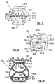
- FIG. 7 shows an embodiment of a polygonal spring body 25 suitable for a multi-part spring element with integrally formed foot and head parts 26.1 and 26.2, which each form receptacles for a footplate and for a support plate.
- the basic shape of this spring body 25 is hexagonal; the spring body 25 consists of the side surfaces 27, which are provided in pairs facing each other in relation to the center plane, the foot part 26.1 and the head part 26.2 closing the polygon.
- the outward angles are overlapped with outer reinforcing webs 27.1, so that the buckling behavior of this spring body 25 can be influenced by the choice of these webs.
- Inner reinforcing webs can also be provided which, as shown in FIG. 6, are arranged symmetrically to the central plane, as shown in FIG.
- tension spring 28 passes through this central plane as a tension spring 28.
- the outer overlapping webs form receiving pockets into which, as shown, internal reinforcement webs 28 with their hammer heads 28.1 can be inserted and anchored, it being self-evident that the side walls 27 in this area of the reinforcement webs the angular edge must be open.
- the internal reinforcement web shown is designed in the illustration as a corrugated tension spring 28; it seems obvious that any other type of tension member can be used. This tension member absorbs the tensile forces occurring between the two free corner edges 16 and stabilizes the spring body, this tension member due to its design, choice of material constants or shape to the desired load conditions can be adjusted.
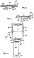
- FIGS. 8 and 9 and 10 show a multi-part spring body 30 for spring elements with an essentially semi-ellipsoidal basic shape, with foot 31.1 and head 31.2, the side walls 32 of which have an indentation 32.1 on both sides.
- these two indentations 32.1 are connected to one another via an inner transverse web 33.1 such that a load in the direction of the main axis of the ellipsoid builds up tensile stress in this transverse web 33.1, which stabilizes the spring body 30 of the spring element.
- the spring body 30 has in the area of its head 31.2 a groove-shaped shape 31.3 for fastening the support plate 35;
- a slat chamber 34 is provided in this embodiment, so that the spring element 35 can be pushed over the slats 5.
- 8 shows the spring body 30 in a schematic perspective and in FIGS. 9 and 10 the spring element with the spring body 30 and the support plate 35 is shown completely in section in a side view (FIG. 9) and in a front view (FIG. 10), the spring body 30 carrying slat (indicated by dashed lines in FIG.
- the term “side view” referring to the open sides of the spring body 30 formed by the hollow profile section, from which the spring action originates.
- the basic form of the spring body 30 of this spring element is a semi-ellipsoid, which is cut off in the region of its short semi-axis to form the foot part 31.1 and is designed as a slat chamber 34, and the tip of which is flat as the head part 31.2.
- the outer wall 32 is advantageously drawn in such that the indentation 32.1 is located approximately in the middle between the foot part 31.1 and the head part 31.2.
- the wall thickness of the outer walls of the spring body 32 can vary over its height, in order to adjust the spring characteristic and to adapt to desired conditions.
- the underside of the spring body 30 is provided with a slat chamber 34, which forms the receptacle for the slat 5 carrying the spring body 30, onto which the spring elements are pushed.
- a fixing knob 34.1 is provided in the slat chamber 34 which engages in a recess (not shown in detail) in the slat 5 and thus fixes the spring body 30 and thus the spring element thereon.
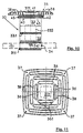
- the head side 31.2 of the spring body 30 is connected to the support plate 35 shown in more detail in FIGS. 11, 12 and 13.
- the head part 31.2, the support plate 35 and the head clamp 40 shown in more detail in FIGS. 14 to 17 are designed such that the support plate 41 and the locking tab 43 of the head clamp 40 encompass the head part 31.2 of the spring body 30, the groove-like recess 31.3 in the head part 31.2 Forms guide groove for the locking tab 43 and receives its corresponding projection 43.1.
- the support plate 35 whose support surface is traversed by ribs 38, has a rib-free area 37 and a central area 37.1 which is also rib-free.
- the ribs 38 are separated from one another by cavities, so that there is sufficient space for the rear ventilation of the support 8 (FIG. 1), which at the same time presses into these cavities, so that an “anchoring" of this support on the support plates 35 occurs counteracts slipping.
- the support plate 41 of the head clamp 40 rests on the guide brackets 36 formed on the support plate 35, on which the head clamp 40 is inserted during assembly, with over-insertion being prevented by end stops 36.1.
- the locking means shown in more detail in FIGS. 14 and 15 are provided on the support plate 35 and consist of a locking lug 36.2 with sliding bevels 36.3, which have the recesses 41.2 in the corresponding side parts of the support plate 41 of the head clamp 40 work together.
- Support plate 41 and locking tab 43 which are pivotally connected to one another via a film hinge, are locked together during assembly by means of locking angles 42 and locking lugs 44, so that both are firmly connected to one another after mounting; thereby engaging in grooves 47 springs 46 ensure that the locking tab in when locking orderly position.
- This simple form is an outflow of the symmetry to the vertical plane which is advantageous for use and divides the spring element in the middle into two mirror-image halves.
- the spring properties can be easily adapted to the requirements by the choice of the material constants and the geometry, the progression of the characteristic curve in particular being able to be influenced by the choice and design of the reinforcements which may be used separately.
- the shape can be such that the wall thickness of the side walls and the receptacles for the head and foot at the edge is (slightly) smaller than in the middle in order to ensure easy removal from the mold when producing in a mold, for example in the case of molded foam.
Landscapes
- Engineering & Computer Science (AREA)
- General Engineering & Computer Science (AREA)
- Mechanical Engineering (AREA)
- Mattresses And Other Support Structures For Chairs And Beds (AREA)
- Golf Clubs (AREA)
- Piezo-Electric Or Mechanical Vibrators, Or Delay Or Filter Circuits (AREA)
- Ultra Sonic Daignosis Equipment (AREA)
- Investigating Or Analyzing Materials By The Use Of Ultrasonic Waves (AREA)
- Springs (AREA)
- Adornments (AREA)
- Electroplating Methods And Accessories (AREA)
Applications Claiming Priority (6)
| Application Number | Priority Date | Filing Date | Title |
|---|---|---|---|
| DE9317114U DE9317114U1 (de) | 1993-11-10 | 1993-11-10 | Polsterelement mit einer Vielzahl von in regelmäßigen Mustern angeordneten Federelementen |
| DE9317114U | 1993-11-10 | ||
| DE9404021U DE9404021U1 (de) | 1994-03-10 | 1994-03-10 | Federelement für Polsterelemente |
| DE9404021U | 1994-03-10 | ||
| DE9412330U | 1994-07-30 | ||
| DE9412330U DE9412330U1 (de) | 1994-07-30 | 1994-07-30 | Federelement für Sitz- oder Liegeflächen |
Publications (3)
| Publication Number | Publication Date |
|---|---|
| EP0653174A2 true EP0653174A2 (fr) | 1995-05-17 |
| EP0653174A3 EP0653174A3 (fr) | 1996-05-29 |
| EP0653174B1 EP0653174B1 (fr) | 1998-12-09 |
Family
ID=27208651
Family Applications (1)
| Application Number | Title | Priority Date | Filing Date |
|---|---|---|---|
| EP94117486A Expired - Lifetime EP0653174B1 (fr) | 1993-11-10 | 1994-11-05 | Elément de rembourrage avec plusieurs éléments de ressort disposés dans des configurations régulières |
Country Status (6)
| Country | Link |
|---|---|
| US (1) | US5588165A (fr) |
| EP (1) | EP0653174B1 (fr) |
| JP (1) | JPH08252151A (fr) |
| AT (1) | ATE174192T1 (fr) |
| DE (1) | DE59407440D1 (fr) |
| DK (1) | DK0653174T3 (fr) |
Cited By (20)
| Publication number | Priority date | Publication date | Assignee | Title |
|---|---|---|---|---|
| EP0734666A1 (fr) * | 1995-03-24 | 1996-10-02 | FROLI Kunststoffe Heinrich Fromme | Support pour coussin |
| DE29614891U1 (de) * | 1995-10-26 | 1996-11-07 | Heidinger, Florian, Dr., 83627 Warngau | Stützelement |
| WO1998011806A1 (fr) * | 1996-09-17 | 1998-03-26 | Ferdinand Baumjohann | Cadre conçu pour un siege ou pour un lit |
| DE29721656U1 (de) * | 1997-12-09 | 1999-01-14 | Froli Kunststoffe Heinrich Fromme, 33758 Schloß Holte-Stukenbrock | Bettsystem |
| WO1999003379A3 (fr) * | 1997-07-18 | 1999-04-15 | Froli Kunststoffwerk Fromme H | Element d'appui pour la base de coussin de surfaces de siege ou de lit |
| DE29909654U1 (de) * | 1999-06-02 | 2000-08-10 | Recticel Internationale Bettsysteme GmbH, 59439 Holzwickede | Federelement zum Einsatz in einem Unterbett |
| FR2793125A1 (fr) * | 1999-05-06 | 2000-11-10 | D E F I S | Suspension pour un sommier du type multi-elements |
| EP0852122A3 (fr) * | 1997-01-03 | 2000-12-20 | Hans Ulrich Dipl.-Ing. Schwenk | Sommier de lit |
| DE19930215A1 (de) * | 1999-06-30 | 2001-01-11 | Rudolf Haddick | Liege- und Sitzelement |
| DE29919967U1 (de) * | 1999-11-13 | 2001-04-05 | Recticel Schlafkomfort GmbH, 44867 Bochum | Bettrahmen mit einer Mehrzahl von die Matratzenauflage bildenden Federelementen |
| EP1099397A1 (fr) | 1999-11-13 | 2001-05-16 | Recticel Schlafkomfort GmbH | Sommier avec une pluralité d'éléments-ressort constituant le support de matelas |
| DE20204740U1 (de) * | 2002-03-26 | 2003-05-15 | Recticel Schlafkomfort Gmbh | Matratze mit einem Kern aus einer Mehrzahl von Federelementen |
| EP1364600A1 (fr) | 2002-05-24 | 2003-11-26 | Delahousse Et Fils | Système de réglage de fermeté pour rotule de sommier |
| EP1602303A2 (fr) | 2004-06-04 | 2005-12-07 | Ennerev Materassi S.P.A. | Dispositif d'amortissement pour matelas |
| EP1733652A1 (fr) * | 2005-06-15 | 2006-12-20 | Recticel Schlafkomfort GmbH | Sommier à lattes comme cadre pour supporter un matelas dans une embase de lit |
| WO2006136840A3 (fr) * | 2005-06-23 | 2007-05-31 | Richard Rhys Mathias | Structure |
| EP2078476A1 (fr) * | 2008-01-11 | 2009-07-15 | Froli Kunststoffwerk Heinrich Fromme OHG | Cadre réglable motorisé pour un lit, une couchette ou analogue |
| WO2016148594A1 (fr) | 2015-03-19 | 2016-09-22 | Mareš Vit | Lit polyvalent qui peut être utilisé également par des personnes ayant des besoins spéciaux |
| WO2017114604A1 (fr) * | 2015-12-28 | 2017-07-06 | Elite Sa | Traverse à ressorts en particulier pour sommier de lit et sommier de lit équipé de traverses à ressorts |
| CN112145602A (zh) * | 2020-09-10 | 2020-12-29 | 天津工业大学 | 一种复合材料弹簧及其制作方法 |
Families Citing this family (73)
| Publication number | Priority date | Publication date | Assignee | Title |
|---|---|---|---|---|
| US6354577B1 (en) * | 1995-06-07 | 2002-03-12 | Sealy Technology Llc | Composite material spring modules with integrally formed attachment fittings |
| DE59605692D1 (de) | 1995-03-22 | 2000-09-14 | Thomas Beteil & Vermoeg Gmbh | Federbrücke für eine Untermatratze |
| DE29516995U1 (de) † | 1995-10-26 | 1996-02-15 | Diemer, Gregor, 85456 Wartenberg | Untermatratze |
| US6113082A (en) * | 1997-06-27 | 2000-09-05 | Nishikawa Sangyo Co., Ltd. | Spring |
| JPH11230223A (ja) * | 1998-02-19 | 1999-08-27 | Honda Motor Co Ltd | 弾性体圧縮ばね |
| US6279998B1 (en) * | 1998-06-05 | 2001-08-28 | Teknion Furniture Systems, Inc. | Seat mounting mechanism |
| GB9820729D0 (en) | 1998-09-24 | 1998-11-18 | Greenhalgh Colin J | Body support and body contour system |
| JP2000125994A (ja) | 1998-10-28 | 2000-05-09 | Aisin Seiki Co Ltd | 樹脂性クッションエレメント |
| DE29903423U1 (de) | 1999-02-25 | 1999-05-12 | Hartmann, Siegbert, 32584 Löhne | Federelement |
| FR2791239B1 (fr) * | 1999-03-25 | 2001-06-08 | Oniris Sa | Dispositif de suspension d'une latte de sommier |
| ES2171339B2 (es) * | 1999-07-09 | 2004-08-01 | Flex Equipos De Descanso S.A. | Sistema amortiguador para somieres de gran anchura, en especial para somieres de lamas. |
| DE19942807C1 (de) * | 1999-09-08 | 2000-12-07 | Matthias Baumjohann | Federelement für Bettrahmen |
| WO2001050923A1 (fr) * | 2000-01-11 | 2001-07-19 | Ivan Martin Hlavac | Element support elastique |
| DE20000477U1 (de) | 2000-01-13 | 2000-03-23 | Weber Erhard | Gekoppelte Wellenbandfederung für Bettunterrahmen und Matratzen |
| DE20001616U1 (de) * | 2000-01-31 | 2001-03-08 | FROLI Kunststoffwerk Heinrich Fromme oHG, 33758 Schloß Holte-Stukenbrock | Lagerelement für Sitz- oder Liegeflächen |
| AU783829B2 (en) | 2000-09-28 | 2005-12-08 | Formway Furniture Limited | A reclinable chair |
| JP4616460B2 (ja) * | 2000-11-15 | 2011-01-19 | シモンズ株式会社 | クッション構成体 |
| ATE280525T1 (de) * | 2001-01-19 | 2004-11-15 | Bock Hermann Gmbh | Bett, insbesondere kranken- und/oder pflegebett |
| US6484339B2 (en) | 2001-01-31 | 2002-11-26 | L & P Property Management Company | Bedding or seating product with nestable stackable modules |
| FR2824246A1 (fr) * | 2001-05-02 | 2002-11-08 | Tournadre Sa Standard Gum | Dispositif de suspension pour sommier du type multi-elements |
| US6598251B2 (en) | 2001-06-15 | 2003-07-29 | Hon Technology Inc. | Body support system |
| FR2832042B1 (fr) | 2001-11-13 | 2004-10-22 | Creations Andre Renault | Sommier et element de suspension pour sommier |
| US7108252B2 (en) * | 2002-03-13 | 2006-09-19 | Ge Medical Systems Global Technology Company, Llc | Method and apparatus for reducing force transmitted from a base structure to a supported structure |
| DE20207113U1 (de) * | 2002-05-04 | 2003-06-18 | FROLI Kunststoffwerk Heinrich Fromme oHG, 33758 Schloß Holte-Stukenbrock | Federlatte für Sitz- oder Liegemöbel |
| DE20300248U1 (de) * | 2002-07-31 | 2003-09-11 | Froli Kunststoffwerk Heinrich | Federelement für Betten |
| WO2005041719A2 (fr) * | 2003-10-23 | 2005-05-12 | Herman Miller, Inc. | Structures et elements de support pixelises |
| PT1532900E (pt) * | 2003-11-18 | 2010-05-25 | Spiroplex Gmbh | ¿elemento de apoio |
| DE20318336U1 (de) * | 2003-11-25 | 2004-02-26 | Hartmann, Siegbert | Einzelfederelement |
| US7458172B2 (en) * | 2004-09-27 | 2008-12-02 | Nike, Inc. | Impact attenuating devices and products containing such devices |
| US7730635B2 (en) * | 2004-09-27 | 2010-06-08 | Nike, Inc. | Impact-attenuation members and products containing such members |
| US7314125B2 (en) | 2004-09-27 | 2008-01-01 | Nike, Inc. | Impact attenuating and spring elements and products containing such elements |
| WO2006072332A1 (fr) * | 2004-12-23 | 2006-07-13 | Esz Wilfried Becker Gmbh | Palier elastomere |
| US7237282B2 (en) * | 2005-01-18 | 2007-07-03 | L&P Property Management Company | Stackable and stable bedding foundation |
| US7740321B2 (en) * | 2006-05-12 | 2010-06-22 | Herman Miller, Inc. | Suspended pixelated seating structure |
| ITMI20061360A1 (it) * | 2006-07-13 | 2008-01-14 | Valentino Fossati | Struttura di molleggio particolarmente per la realizzazione di materassi e simili |
| US7832040B2 (en) * | 2007-01-24 | 2010-11-16 | Sealy Technology Llc | Suspended flexible matrix support system |
| CN102772053A (zh) | 2007-01-29 | 2012-11-14 | 赫尔曼米勒有限公司 | 座位结构及其使用方法 |
| US8011865B2 (en) | 2007-04-12 | 2011-09-06 | Standard Car Truck Company | Railroad car coil restraint system |
| GB2449888A (en) * | 2007-06-06 | 2008-12-10 | Richard Rhys Mathias | Collapsible structure for a folding bed |
| USD597771S1 (en) | 2008-01-28 | 2009-08-11 | Herman Miller, Inc. | Backrest |
| USD587914S1 (en) | 2008-01-28 | 2009-03-10 | Herman Miller, Inc. | Chair |
| MX2010013292A (es) | 2008-06-04 | 2010-12-21 | Miller Herman Inc | Asiento de suspension. |
| WO2010011633A1 (fr) | 2008-07-25 | 2010-01-28 | Herman Miller, Inc. | Structure de support multicouche |
| FR2942381B1 (fr) * | 2009-02-23 | 2011-02-25 | Creations Andre Renault | Dispositif de suspension a plateau ajoure pour sommier et sommier correspondant |
| US20120200018A1 (en) * | 2009-09-03 | 2012-08-09 | Keter Plastic Ltd | Device, system, and method of injected padding |
| US10070724B2 (en) * | 2009-12-17 | 2018-09-11 | Matthew Jacobs | Rocker style chairs, modular components for use within rocker style chairs and parts for use within the modular components |
| US8726424B2 (en) | 2010-06-03 | 2014-05-20 | Intellectual Property Holdings, Llc | Energy management structure |
| FR2975575B1 (fr) * | 2011-05-24 | 2014-09-05 | Tournadre Sa Standard Gum | Element de suspension de coussin ou de matelas |
| US9516910B2 (en) | 2011-07-01 | 2016-12-13 | Intellectual Property Holdings, Llc | Helmet impact liner system |
| US20130086733A1 (en) * | 2011-10-10 | 2013-04-11 | Intellectual Property Holdings, Llc | Helmet impact liner system |
| CN102588487B (zh) * | 2012-02-21 | 2014-05-21 | 喜临门家具股份有限公司 | 一种变径圆柱式气压弹簧 |
| US9320311B2 (en) | 2012-05-02 | 2016-04-26 | Intellectual Property Holdings, Llc | Helmet impact liner system |
| US9894953B2 (en) | 2012-10-04 | 2018-02-20 | Intellectual Property Holdings, Llc | Helmet retention system |
| US20140283302A1 (en) * | 2013-03-23 | 2014-09-25 | Uwe Horstmann | Device for the insertion in bedsteads, bedding boxes or bed frames for use as a lying surface with a mattress on top of it for primarily a single person |
| US9456657B2 (en) * | 2013-07-31 | 2016-10-04 | Nike, Inc. | Article of footwear with support assembly having tubular members |
| WO2015065902A1 (fr) | 2013-10-28 | 2015-05-07 | Intellectual Property Holdings, Llc | Système de retenue de casque |
| US9474313B2 (en) * | 2013-12-16 | 2016-10-25 | Brian Kamradt | Energy absorbing and displacing structure for body protective padding |
| US9901185B2 (en) * | 2014-01-31 | 2018-02-27 | Dreamwell, Ltd. | Mattress including flat springs |
| CA2946579C (fr) | 2014-04-24 | 2017-09-12 | Ashley Furniture Industries, Inc. | Plateau de siege rabattable pour ensembles meubles |
| USD782861S1 (en) * | 2014-10-08 | 2017-04-04 | Froli Kunststoffwerk Heinrich Fromme Inhaberine Margret Fromme-Ruthmann E. Kfr. | Grid spring assembly |
| DE202014104824U1 (de) * | 2014-10-08 | 2015-10-09 | Froli Kunststoffwerk Heinrich Fromme, Inh. Margret Fromme-Ruthmann E.Kfr. | Anordnung mit mehreren Federelementen für eine Polsterunterlage |
| US9848709B2 (en) * | 2015-06-04 | 2017-12-26 | Donald J. Molenda | Multi layered modular support system for lounge and other applications |
| US10034516B2 (en) * | 2016-02-16 | 2018-07-31 | Nike, Inc. | Footwear sole structure |
| CN107518671B (zh) * | 2016-06-22 | 2020-05-05 | 明门香港股份有限公司 | 床垫及强化板 |
| US9955801B2 (en) | 2016-06-22 | 2018-05-01 | Wonderland Switzerland Ag | Baby carriage |
| CN112674536B (zh) * | 2019-10-17 | 2024-08-02 | 厦门新技术集成有限公司 | 用于家具的弹性模块和弹性垫 |
| DE202020103217U1 (de) * | 2020-06-04 | 2021-06-07 | Froli Kunststoffwerk Heinrich Fromme, Inh. Margret Fromme-Ruthmann E.Kfr. | Kombiniertes Sitz- und Schlafmöbel und Bausatz |
| DE202020106193U1 (de) * | 2020-10-29 | 2022-02-01 | Froli Kunststoffwerk Heinrich Fromme, Inh. Margret Fromme-Ruthmann E.Kfr. | Federbauteil für ein Sitzmöbel, Anordnung für ein Sitzmöbel und Sitzmöbel |
| CN115251636A (zh) * | 2021-04-29 | 2022-11-01 | 厦门新技术集成有限公司 | 沙发床 |
| US12365275B2 (en) * | 2021-09-03 | 2025-07-22 | Roswell Canada Inc. | Suspension component |
| CN115590332A (zh) * | 2021-12-02 | 2023-01-13 | 厦门新技术集成有限公司(Cn) | 弹性支撑模块、弹性垫和家具 |
| CN115005632B (zh) * | 2022-06-13 | 2023-07-04 | 宁波梦神床垫机械有限公司 | 一种多形态弹簧组合睡感床垫的调节装置 |
| CN115251652B (zh) * | 2022-07-11 | 2023-07-04 | 宁波梦神床垫机械有限公司 | 一种配弹簧底座床垫 |
Family Cites Families (2)
| Publication number | Priority date | Publication date | Assignee | Title |
|---|---|---|---|---|
| DE8813387U1 (de) * | 1988-10-25 | 1989-02-02 | Rössle & Wanner GmbH, 7403 Ammerbuch | Lagerkörper |
| CH681950A5 (fr) * | 1989-06-08 | 1993-06-30 | Superba Sa |
-
1994
- 1994-11-05 EP EP94117486A patent/EP0653174B1/fr not_active Expired - Lifetime
- 1994-11-05 AT AT94117486T patent/ATE174192T1/de not_active IP Right Cessation
- 1994-11-05 DE DE59407440T patent/DE59407440D1/de not_active Expired - Lifetime
- 1994-11-05 DK DK94117486T patent/DK0653174T3/da active
- 1994-11-10 US US08/338,804 patent/US5588165A/en not_active Expired - Lifetime
-
1995
- 1995-03-10 JP JP7051532A patent/JPH08252151A/ja active Pending
Cited By (26)
| Publication number | Priority date | Publication date | Assignee | Title |
|---|---|---|---|---|
| EP0734666A1 (fr) * | 1995-03-24 | 1996-10-02 | FROLI Kunststoffe Heinrich Fromme | Support pour coussin |
| DE29614891U1 (de) * | 1995-10-26 | 1996-11-07 | Heidinger, Florian, Dr., 83627 Warngau | Stützelement |
| WO1998011806A1 (fr) * | 1996-09-17 | 1998-03-26 | Ferdinand Baumjohann | Cadre conçu pour un siege ou pour un lit |
| EP0852122A3 (fr) * | 1997-01-03 | 2000-12-20 | Hans Ulrich Dipl.-Ing. Schwenk | Sommier de lit |
| WO1999003379A3 (fr) * | 1997-07-18 | 1999-04-15 | Froli Kunststoffwerk Fromme H | Element d'appui pour la base de coussin de surfaces de siege ou de lit |
| DE29721656U1 (de) * | 1997-12-09 | 1999-01-14 | Froli Kunststoffe Heinrich Fromme, 33758 Schloß Holte-Stukenbrock | Bettsystem |
| FR2793125A1 (fr) * | 1999-05-06 | 2000-11-10 | D E F I S | Suspension pour un sommier du type multi-elements |
| WO2000067618A1 (fr) | 1999-05-06 | 2000-11-16 | D.E.F.I.S. | Suspension pour un sommier du type multi-elements |
| DE29909654U1 (de) * | 1999-06-02 | 2000-08-10 | Recticel Internationale Bettsysteme GmbH, 59439 Holzwickede | Federelement zum Einsatz in einem Unterbett |
| EP1057433A1 (fr) | 1999-06-02 | 2000-12-06 | Recticel Internationale Bettsysteme GmbH | Elément ressort pour utilisation dans un sommier |
| DE19930215A1 (de) * | 1999-06-30 | 2001-01-11 | Rudolf Haddick | Liege- und Sitzelement |
| DE19930215C2 (de) * | 1999-06-30 | 2002-06-27 | Rudolf Haddick | Liege- und Sitzelement |
| EP1099397A1 (fr) | 1999-11-13 | 2001-05-16 | Recticel Schlafkomfort GmbH | Sommier avec une pluralité d'éléments-ressort constituant le support de matelas |
| DE29919967U1 (de) * | 1999-11-13 | 2001-04-05 | Recticel Schlafkomfort GmbH, 44867 Bochum | Bettrahmen mit einer Mehrzahl von die Matratzenauflage bildenden Federelementen |
| DE20204740U1 (de) * | 2002-03-26 | 2003-05-15 | Recticel Schlafkomfort Gmbh | Matratze mit einem Kern aus einer Mehrzahl von Federelementen |
| EP1348358A2 (fr) | 2002-03-26 | 2003-10-01 | Recticel Schlafkomfort GmbH | Matelas avec un noyau comportant plusieurs éléments de ressort |
| EP1364600A1 (fr) | 2002-05-24 | 2003-11-26 | Delahousse Et Fils | Système de réglage de fermeté pour rotule de sommier |
| FR2839870A1 (fr) | 2002-05-24 | 2003-11-28 | Delahousse Et Fils Sa | Systeme de reglage de fermete pour rotule de sommier |
| EP1602303A3 (fr) * | 2004-06-04 | 2006-11-08 | Ennerev Materassi S.P.A. | Dispositif d'amortissement pour matelas |
| EP1602303A2 (fr) | 2004-06-04 | 2005-12-07 | Ennerev Materassi S.P.A. | Dispositif d'amortissement pour matelas |
| EP1733652A1 (fr) * | 2005-06-15 | 2006-12-20 | Recticel Schlafkomfort GmbH | Sommier à lattes comme cadre pour supporter un matelas dans une embase de lit |
| WO2006136840A3 (fr) * | 2005-06-23 | 2007-05-31 | Richard Rhys Mathias | Structure |
| EP2078476A1 (fr) * | 2008-01-11 | 2009-07-15 | Froli Kunststoffwerk Heinrich Fromme OHG | Cadre réglable motorisé pour un lit, une couchette ou analogue |
| WO2016148594A1 (fr) | 2015-03-19 | 2016-09-22 | Mareš Vit | Lit polyvalent qui peut être utilisé également par des personnes ayant des besoins spéciaux |
| WO2017114604A1 (fr) * | 2015-12-28 | 2017-07-06 | Elite Sa | Traverse à ressorts en particulier pour sommier de lit et sommier de lit équipé de traverses à ressorts |
| CN112145602A (zh) * | 2020-09-10 | 2020-12-29 | 天津工业大学 | 一种复合材料弹簧及其制作方法 |
Also Published As
| Publication number | Publication date |
|---|---|
| US5588165A (en) | 1996-12-31 |
| EP0653174B1 (fr) | 1998-12-09 |
| EP0653174A3 (fr) | 1996-05-29 |
| DK0653174T3 (da) | 1999-08-16 |
| JPH08252151A (ja) | 1996-10-01 |
| ATE174192T1 (de) | 1998-12-15 |
| DE59407440D1 (de) | 1999-01-21 |
Similar Documents
| Publication | Publication Date | Title |
|---|---|---|
| EP0653174B1 (fr) | Elément de rembourrage avec plusieurs éléments de ressort disposés dans des configurations régulières | |
| EP0734666B1 (fr) | Support pour coussin | |
| EP0118652B1 (fr) | Sommier à lattes | |
| DE69916473T2 (de) | Körperstütze | |
| EP2779869B1 (fr) | Suspension à ressort, en particulier pour matelas | |
| DE9317114U1 (de) | Polsterelement mit einer Vielzahl von in regelmäßigen Mustern angeordneten Federelementen | |
| EP1959797B1 (fr) | Matelas | |
| EP3426103B1 (fr) | Housse de matelas ou de capitonnage ainsi que matelas ou capitonnage pourvu d'une telle housse | |
| DE19945724A1 (de) | Unterfederung für Matratzen oder dergleichen und Verwendung derselben | |
| DE29611876U1 (de) | Endfeder zur gefederten Lagerung von Latten eines Lattenrostes | |
| WO2017148594A1 (fr) | Suspension à ressort pour un rembourrage et meuble doté d'une telle suspension à ressort | |
| DE29721656U1 (de) | Bettsystem | |
| EP0439712B1 (fr) | Châlit ou dispositif similaire de repos | |
| DE9404021U1 (de) | Federelement für Polsterelemente | |
| DE69100905T2 (de) | Lattenrost. | |
| EP3069634B1 (fr) | Latte pour suspension a ressort equipant un siege ou un lit | |
| EP1820423A1 (fr) | Console pour des lattes réglable en hauteur dans un sommier à latttes | |
| DE202017100229U1 (de) | Bettunterbau | |
| DE9412330U1 (de) | Federelement für Sitz- oder Liegeflächen | |
| DE4341349A1 (de) | Unterbau für Polsterelemente mit einer Vielzahl von zwischen zwei Seitenholmen parallel zueinander verlaufenden Latten | |
| EP1001696A1 (fr) | Support permettant de s'asseoir ou de s'allonger | |
| EP0646341A1 (fr) | Grille de support pour meuble d'assise ou de couchage, et éléments de support | |
| DE7708191U1 (de) | Sprungrahmen mit lattenrost | |
| EP1302135A2 (fr) | Siège ou lit comprenant une pluralité d'éléments ressorts et procédé de fabrication de ces éléments de ressorts | |
| EP2160121A1 (fr) | Agencement comprenant une structure de lit et un matelas combiné |
Legal Events
| Date | Code | Title | Description |
|---|---|---|---|
| PUAI | Public reference made under article 153(3) epc to a published international application that has entered the european phase |
Free format text: ORIGINAL CODE: 0009012 |
|
| AK | Designated contracting states |
Kind code of ref document: A2 Designated state(s): AT BE CH DE DK FR GB LI NL SE |
|
| PUAL | Search report despatched |
Free format text: ORIGINAL CODE: 0009013 |
|
| AK | Designated contracting states |
Kind code of ref document: A3 Designated state(s): AT BE CH DE DK FR GB LI NL SE |
|
| 17P | Request for examination filed |
Effective date: 19960704 |
|
| 17Q | First examination report despatched |
Effective date: 19970509 |
|
| GRAG | Despatch of communication of intention to grant |
Free format text: ORIGINAL CODE: EPIDOS AGRA |
|
| GRAG | Despatch of communication of intention to grant |
Free format text: ORIGINAL CODE: EPIDOS AGRA |
|
| GRAH | Despatch of communication of intention to grant a patent |
Free format text: ORIGINAL CODE: EPIDOS IGRA |
|
| GRAH | Despatch of communication of intention to grant a patent |
Free format text: ORIGINAL CODE: EPIDOS IGRA |
|
| GRAA | (expected) grant |
Free format text: ORIGINAL CODE: 0009210 |
|
| AK | Designated contracting states |
Kind code of ref document: B1 Designated state(s): AT BE CH DE DK FR GB LI NL SE |
|
| REF | Corresponds to: |
Ref document number: 174192 Country of ref document: AT Date of ref document: 19981215 Kind code of ref document: T |
|
| REG | Reference to a national code |
Ref country code: CH Ref legal event code: EP |
|
| REF | Corresponds to: |
Ref document number: 59407440 Country of ref document: DE Date of ref document: 19990121 |
|
| ET | Fr: translation filed | ||
| GBT | Gb: translation of ep patent filed (gb section 77(6)(a)/1977) |
Effective date: 19990222 |
|
| REG | Reference to a national code |
Ref country code: CH Ref legal event code: NV Representative=s name: BOVARD AG PATENTANWAELTE |
|
| REG | Reference to a national code |
Ref country code: DK Ref legal event code: T3 |
|
| PLBE | No opposition filed within time limit |
Free format text: ORIGINAL CODE: 0009261 |
|
| STAA | Information on the status of an ep patent application or granted ep patent |
Free format text: STATUS: NO OPPOSITION FILED WITHIN TIME LIMIT |
|
| 26N | No opposition filed | ||
| REG | Reference to a national code |
Ref country code: GB Ref legal event code: IF02 |
|
| PGFP | Annual fee paid to national office [announced via postgrant information from national office to epo] |
Ref country code: SE Payment date: 20091120 Year of fee payment: 16 Ref country code: DK Payment date: 20091124 Year of fee payment: 16 Ref country code: CH Payment date: 20091124 Year of fee payment: 16 Ref country code: AT Payment date: 20091120 Year of fee payment: 16 |
|
| PGFP | Annual fee paid to national office [announced via postgrant information from national office to epo] |
Ref country code: NL Payment date: 20091123 Year of fee payment: 16 |
|
| PGFP | Annual fee paid to national office [announced via postgrant information from national office to epo] |
Ref country code: GB Payment date: 20091123 Year of fee payment: 16 Ref country code: FR Payment date: 20091202 Year of fee payment: 16 |
|
| PGFP | Annual fee paid to national office [announced via postgrant information from national office to epo] |
Ref country code: BE Payment date: 20091123 Year of fee payment: 16 |
|
| REG | Reference to a national code |
Ref country code: CH Ref legal event code: PFA Owner name: SENNE LIZENZ + PRODUKTE GMBH Free format text: SENNE LIZENZ + PRODUKTE GMBH#LIEMKER STRASSE 27#D-33758 SCHLOSS HOLTE-STUKENBROCK (DE) -TRANSFER TO- SENNE LIZENZ + PRODUKTE GMBH#LIEMKER STRASSE 27#D-33758 SCHLOSS HOLTE-STUKENBROCK (DE) |
|
| BERE | Be: lapsed |
Owner name: *SENNE LIZENZ + PRODUKTE G.M.B.H. Effective date: 20101130 |
|
| REG | Reference to a national code |
Ref country code: NL Ref legal event code: V1 Effective date: 20110601 |
|
| REG | Reference to a national code |
Ref country code: SE Ref legal event code: EUG |
|
| REG | Reference to a national code |
Ref country code: CH Ref legal event code: PL |
|
| REG | Reference to a national code |
Ref country code: DK Ref legal event code: EBP |
|
| GBPC | Gb: european patent ceased through non-payment of renewal fee |
Effective date: 20101105 |
|
| PG25 | Lapsed in a contracting state [announced via postgrant information from national office to epo] |
Ref country code: LI Free format text: LAPSE BECAUSE OF NON-PAYMENT OF DUE FEES Effective date: 20101130 Ref country code: CH Free format text: LAPSE BECAUSE OF NON-PAYMENT OF DUE FEES Effective date: 20101130 |
|
| REG | Reference to a national code |
Ref country code: FR Ref legal event code: ST Effective date: 20110801 |
|
| PG25 | Lapsed in a contracting state [announced via postgrant information from national office to epo] |
Ref country code: AT Free format text: LAPSE BECAUSE OF NON-PAYMENT OF DUE FEES Effective date: 20101105 Ref country code: NL Free format text: LAPSE BECAUSE OF NON-PAYMENT OF DUE FEES Effective date: 20110601 Ref country code: BE Free format text: LAPSE BECAUSE OF NON-PAYMENT OF DUE FEES Effective date: 20101130 |
|
| PG25 | Lapsed in a contracting state [announced via postgrant information from national office to epo] |
Ref country code: SE Free format text: LAPSE BECAUSE OF NON-PAYMENT OF DUE FEES Effective date: 20101106 |
|
| PG25 | Lapsed in a contracting state [announced via postgrant information from national office to epo] |
Ref country code: DK Free format text: LAPSE BECAUSE OF NON-PAYMENT OF DUE FEES Effective date: 20101130 Ref country code: FR Free format text: LAPSE BECAUSE OF NON-PAYMENT OF DUE FEES Effective date: 20101130 |
|
| PG25 | Lapsed in a contracting state [announced via postgrant information from national office to epo] |
Ref country code: GB Free format text: LAPSE BECAUSE OF NON-PAYMENT OF DUE FEES Effective date: 20101105 |
|
| PGFP | Annual fee paid to national office [announced via postgrant information from national office to epo] |
Ref country code: DE Payment date: 20140115 Year of fee payment: 20 |
|
| REG | Reference to a national code |
Ref country code: DE Ref legal event code: R071 Ref document number: 59407440 Country of ref document: DE |