EP0653268A1 - Fördervorrichtung mit Trägereinheit mit Stossfänger und Bremsfähigkeit und Verfahren zum stossfreien Fördern - Google Patents
Fördervorrichtung mit Trägereinheit mit Stossfänger und Bremsfähigkeit und Verfahren zum stossfreien Fördern Download PDFInfo
- Publication number
- EP0653268A1 EP0653268A1 EP94305181A EP94305181A EP0653268A1 EP 0653268 A1 EP0653268 A1 EP 0653268A1 EP 94305181 A EP94305181 A EP 94305181A EP 94305181 A EP94305181 A EP 94305181A EP 0653268 A1 EP0653268 A1 EP 0653268A1
- Authority
- EP
- European Patent Office
- Prior art keywords
- carrier
- undersurface
- conveyor
- ring
- guide
- Prior art date
- Legal status (The legal status is an assumption and is not a legal conclusion. Google has not performed a legal analysis and makes no representation as to the accuracy of the status listed.)
- Granted
Links
- 230000035939 shock Effects 0.000 title claims abstract description 23
- 238000000034 method Methods 0.000 title claims description 5
- 239000000872 buffer Substances 0.000 claims abstract description 32
- 230000033001 locomotion Effects 0.000 claims description 9
- 230000003247 decreasing effect Effects 0.000 claims 4
- 230000003213 activating effect Effects 0.000 claims 1
- 239000000969 carrier Substances 0.000 abstract description 31
- 230000006835 compression Effects 0.000 abstract description 2
- 238000007906 compression Methods 0.000 abstract description 2
- 239000006096 absorbing agent Substances 0.000 description 12
- 230000001360 synchronised effect Effects 0.000 description 11
- 238000013461 design Methods 0.000 description 3
- 238000012986 modification Methods 0.000 description 2
- 230000004048 modification Effects 0.000 description 2
- 238000010521 absorption reaction Methods 0.000 description 1
- 238000013459 approach Methods 0.000 description 1
- 230000000712 assembly Effects 0.000 description 1
- 238000000429 assembly Methods 0.000 description 1
- 230000005540 biological transmission Effects 0.000 description 1
- 238000006073 displacement reaction Methods 0.000 description 1
- 230000000694 effects Effects 0.000 description 1
- 238000004519 manufacturing process Methods 0.000 description 1
- 238000012545 processing Methods 0.000 description 1
- 238000011144 upstream manufacturing Methods 0.000 description 1
Images
Classifications
-
- B—PERFORMING OPERATIONS; TRANSPORTING
- B65—CONVEYING; PACKING; STORING; HANDLING THIN OR FILAMENTARY MATERIAL
- B65G—TRANSPORT OR STORAGE DEVICES, e.g. CONVEYORS FOR LOADING OR TIPPING, SHOP CONVEYOR SYSTEMS OR PNEUMATIC TUBE CONVEYORS
- B65G17/00—Conveyors having an endless traction element, e.g. a chain, transmitting movement to a continuous or substantially-continuous load-carrying surface or to a series of individual load-carriers; Endless-chain conveyors in which the chains form the load-carrying surface
- B65G17/002—Conveyors having an endless traction element, e.g. a chain, transmitting movement to a continuous or substantially-continuous load-carrying surface or to a series of individual load-carriers; Endless-chain conveyors in which the chains form the load-carrying surface comprising load carriers resting on the traction element
-
- B—PERFORMING OPERATIONS; TRANSPORTING
- B65—CONVEYING; PACKING; STORING; HANDLING THIN OR FILAMENTARY MATERIAL
- B65G—TRANSPORT OR STORAGE DEVICES, e.g. CONVEYORS FOR LOADING OR TIPPING, SHOP CONVEYOR SYSTEMS OR PNEUMATIC TUBE CONVEYORS
- B65G2201/00—Indexing codes relating to handling devices, e.g. conveyors, characterised by the type of product or load being conveyed or handled
- B65G2201/02—Articles
Definitions
- the present invention makes a significant contribution to the art of asynchronous automatic conveyor systems by providing an improved carrier equipped with both a bumper or shock absorbing means and braking means.
- the present invention provides a carrier with braking capabilities without extensive design modifications to existing carriers and further without any design modifications to the conveyor system, conveyor chain or support frames that support the conveyor chain.
- the ring When the flexible ring is engaged by an oncoming carrier, the ring is simultaneously compressed in the longitudinal (or forward-rearward) direction and expands in the lateral (or side-to-side) direction.
- the lateral expansion of the ring causes the ring to engage the upwardly protruding sidewalls of the track section or support frame that accommodates the conveyor.
- the frictional engagement of the ring against the sidewalls of the track fixes the queued carrier in place; the force absorbing ability of the flexible ring, and its ability to divert shock forces outwardly toward the sidewall of the carrier support acts to brake the queued carrier as it is engaged by the oncoming carrier.
- the flexible ring is accommodated within a channel or space disposed in the rear pallet guide.
- the rear pallet guide includes a rearwardly facing wall and a rear post.
- the channel that accommodates the ring is bound by the rear wall, which is preferably arcuately shaped, the rear post, a bottom surface of the channel, and the undersurface of the carrier.
- the rear pallet guide is preferably attached to the carrier at the rear wall and at the rear post which, in addition to the bottom of the channel and the undersurface of the carrier, define the channel that accommodates the flexible ring.
- the flexible ring is attached to the rear pallet guide and therefore is fixedly attached to the carrier.
- the flexible ring is mounted to the front end of the carrier.
- the front carrier guide is designed in a manner similar to the rear carrier guide as discussed above and the rear carrier guide would be a standard carrier guide as discussed above.
- the front flexible ring on an oncoming carrier would then act to protect its associated carrier from undue amounts of shock and vibration caused by its collision with a queued carrier or other object in its path.
- the flexible ring carried by the front of said oncoming carrier would compress upon collision and act as a brake for the oncoming carrier.
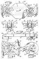
- the carrier 11a shown at the right has engaged or otherwise slammed into the carrier 11b shown at the left.
- the ring 28 engages the front carrier guide 21 and compresses in the longitudinal or front-to-rear direction.
- the longitudinal compression of the ring 28 results in lateral expansion of the ring 28.
- the ring 28 engages the side walls 36, 37 of the frame 27.
- the result is a frictional engagement between the ring 28 and the side walls 36, 37, the frictional engagement braking the forward movement of the carrier 11b in the direction of the arrow 38 (see also Figure 1).
- Collision of the ring 28 with the rear carrier guide 22 also results in substantial shock absorption by the flexible ring 28.
- the flexible ring 28, indicated in phantom, is disposed within an arcuate channel or space, shown generally at 29.
- the channel 29 is bound by a rear arcuate or concave wall 31 and a post 32.
- the post or wall 32 is oblong in shape and also serves as a means to attach the rear carrier guide 22 to the undersurface 19 of the pallet 15.
- the bolt 34 (See Figure 4) is accommodated in the hole 43 disposed in the oblong post 32.
- the rear carrier guide 22 is also attached to the undersurface 19 of the pallet 15 at the hole 42 disposed aft of the rear wall 31 which accommodates the bolt 33 (See Figure 4).
Landscapes
- Engineering & Computer Science (AREA)
- Mechanical Engineering (AREA)
- Special Conveying (AREA)
- Branching, Merging, And Special Transfer Between Conveyors (AREA)
- Automatic Assembly (AREA)
- Intermediate Stations On Conveyors (AREA)
- Automobile Manufacture Line, Endless Track Vehicle, Trailer (AREA)
Applications Claiming Priority (2)
| Application Number | Priority Date | Filing Date | Title |
|---|---|---|---|
| US150922 | 1993-11-11 | ||
| US08/150,922 US5372240A (en) | 1993-11-12 | 1993-11-12 | Conveying system having carrier unit with bumper and braking capabilities and method of shock free conveying |
Publications (2)
| Publication Number | Publication Date |
|---|---|
| EP0653268A1 true EP0653268A1 (de) | 1995-05-17 |
| EP0653268B1 EP0653268B1 (de) | 1998-10-21 |
Family
ID=22536565
Family Applications (1)
| Application Number | Title | Priority Date | Filing Date |
|---|---|---|---|
| EP94305181A Expired - Lifetime EP0653268B1 (de) | 1993-11-11 | 1994-07-14 | Fördervorrichtung mit Trägereinheit mit Stossfänger und Bremsfähigkeit und Verfahren zum stossfreien Fördern |
Country Status (5)
| Country | Link |
|---|---|
| US (1) | US5372240A (de) |
| EP (1) | EP0653268B1 (de) |
| JP (1) | JP3102458B2 (de) |
| CA (1) | CA2127956C (de) |
| DE (1) | DE69414073T2 (de) |
Cited By (1)
| Publication number | Priority date | Publication date | Assignee | Title |
|---|---|---|---|---|
| CN102648136A (zh) * | 2009-09-04 | 2012-08-22 | 柔性连接部件股份公司 | 运载器圆盘 |
Families Citing this family (17)
| Publication number | Priority date | Publication date | Assignee | Title |
|---|---|---|---|---|
| US6102194A (en) * | 1999-02-16 | 2000-08-15 | Belcan Corporation | Pallet type transfer device |
| JP3615095B2 (ja) * | 1999-09-21 | 2005-01-26 | 株式会社椿本チエイン | 自動車製造ライン用フリクション駆動式フロアーコンベヤ |
| US6460684B1 (en) | 2000-04-28 | 2002-10-08 | Wes-Tech, Inc. | Bumper carrier and support |
| SE523190C2 (sv) * | 2001-12-21 | 2004-03-30 | Flexlink Components Ab | Anordning för bromsande arrangemang vid detta samt förfarande för bromsande |
| DE10201841A1 (de) * | 2002-01-16 | 2003-07-24 | Minitec Maschb Gmbh & Co Kg | Palette zum Transport von Gütern auf einem Förderband |
| DE502004001435D1 (de) * | 2004-10-30 | 2006-10-19 | Ewab Holding Ag | Werkstückträger für eine Werkstückfördereinrichtung mit einer Förderkette und einer Führungsbahn |
| US7380648B2 (en) * | 2004-12-03 | 2008-06-03 | Mmc Automation Inc. | Workpiece carrier and anti-backlash mechanism therefor |
| DE502007004045D1 (de) * | 2007-02-16 | 2010-07-15 | Rsl Logistik Gmbh & Co Kg | Fördermittel für eine hängefördereinrichtung |
| JP5295247B2 (ja) * | 2007-09-14 | 2013-09-18 | フレックスリンク コンポーネンツ アーベー | パレット及びパレットシステム |
| US8640859B2 (en) * | 2010-03-30 | 2014-02-04 | Ats Automation Tooling Systems Inc. | Conveyor pallet and guiding system |
| SE535457C2 (sv) | 2010-09-24 | 2012-08-14 | Flexlink Components Ab | Bärarpuck |
| EP2691323B1 (de) * | 2011-03-31 | 2016-05-18 | ATS Automation Tooling Systems Inc. | System zum automatischen fördern von komponenten über ein fliessband |
| DE102014014133A1 (de) * | 2014-09-30 | 2016-03-31 | Liebherr-Verzahntechnik Gmbh | Werkstückträger |
| WO2017074484A1 (en) * | 2015-10-25 | 2017-05-04 | Applied Materials, Inc. | Apparatus for vacuum deposition on a substrate and method for masking the substrate during vacuum deposition |
| DE102017113953B3 (de) * | 2017-06-23 | 2018-10-31 | Flexlink Ab | Passive Transportvorrichtung zum Transportieren von Fördergut sowie Transportsystem, Verfahren sowie Steuerungsverfahren hierzu |
| FR3092100A1 (fr) * | 2019-01-30 | 2020-07-31 | Fives Cinetic | Palette pour convoyeur a chaine, et convoyeur associe |
| CN120839593B (zh) * | 2025-09-23 | 2025-11-28 | 万向钱潮股份公司 | 一种内圈供给装置及方法 |
Citations (10)
| Publication number | Priority date | Publication date | Assignee | Title |
|---|---|---|---|---|
| US3049214A (en) * | 1959-09-22 | 1962-08-14 | Gen Electric | Electron tube assembly apparatus |
| US4095687A (en) * | 1976-10-19 | 1978-06-20 | Standard Tool & Manufacturing Co | Escapement mechanism for pallet control |
| GB2010138A (en) * | 1977-12-15 | 1979-06-27 | Sticht W | Plant for manufacturing components in two or more steps |
| JPS55156119A (en) * | 1979-05-18 | 1980-12-04 | Matsushita Electric Ind Co Ltd | Pallet conveyor |
| JPS579622A (en) * | 1980-06-17 | 1982-01-19 | Matsushita Electric Ind Co Ltd | Buffer for pallet |
| US4605121A (en) * | 1984-05-30 | 1986-08-12 | Ewab Ejvin Wahren Ab | Arresting buffer for objects on conveyors |
| JPS62295815A (ja) * | 1986-06-11 | 1987-12-23 | Pfu Ltd | 給電装置を備えたワ−ク搬送装置 |
| JPH0248321A (ja) * | 1988-08-08 | 1990-02-19 | Matsushita Electric Ind Co Ltd | パレットの搬送装置 |
| JPH02123015A (ja) * | 1988-10-28 | 1990-05-10 | Matsushita Electric Ind Co Ltd | パレット停止装置 |
| GB2270296A (en) * | 1992-09-07 | 1994-03-09 | Modular Automation Limited | Assembly line system and pallet therefor. |
Family Cites Families (12)
| Publication number | Priority date | Publication date | Assignee | Title |
|---|---|---|---|---|
| US2424055A (en) * | 1944-07-20 | 1947-07-15 | Rousseau Claude | Hook conveyer |
| US4168775A (en) * | 1977-07-12 | 1979-09-25 | Actus, Inc. | Idler sprockets for sample changer tracks |
| US4220435A (en) * | 1978-08-21 | 1980-09-02 | F. Jos. Lamb Company | Unloader for ring-shaped pallets |
| DE8704208U1 (de) * | 1987-03-20 | 1988-07-21 | Robert Bosch Gmbh, 70469 Stuttgart | Hub- und Positioniervorrichtung für plattenförmige Werkstückträger |
| GB2214888A (en) * | 1988-02-16 | 1989-09-13 | Kuikka George Ltd | Improvements in tracks for conveyor systems |
| US5170876A (en) * | 1988-03-03 | 1992-12-15 | Walter Sticht | Installation for manufacturing and/or assembling components |
| US5007527A (en) * | 1988-04-08 | 1991-04-16 | Honeywell Inc. | Pallet having a sidewall comprising an arcuate surface |
| US5090556A (en) * | 1988-06-08 | 1992-02-25 | Honeywell Inc. | Pallet transfer corner system |
| US4946025A (en) * | 1988-11-28 | 1990-08-07 | Simplimatic Engineering Company | Apparatus and method for separating articles on a conveyor |
| DE4010697A1 (de) * | 1990-04-03 | 1991-10-10 | Protech Automation Gmbh | Montagestation |
| JPH0427131A (ja) * | 1990-05-22 | 1992-01-30 | Ibiden Co Ltd | 電子部品搭載用基板 |
| DE4125961C2 (de) * | 1991-08-06 | 1995-04-06 | Giddings & Lewis Gmbh | Werkstückpalette als Werkstückträger für Transferstraßen |
-
1993
- 1993-11-12 US US08/150,922 patent/US5372240A/en not_active Expired - Lifetime
-
1994
- 1994-07-13 CA CA002127956A patent/CA2127956C/en not_active Expired - Fee Related
- 1994-07-14 DE DE69414073T patent/DE69414073T2/de not_active Expired - Fee Related
- 1994-07-14 EP EP94305181A patent/EP0653268B1/de not_active Expired - Lifetime
- 1994-08-10 JP JP06209074A patent/JP3102458B2/ja not_active Expired - Fee Related
Patent Citations (10)
| Publication number | Priority date | Publication date | Assignee | Title |
|---|---|---|---|---|
| US3049214A (en) * | 1959-09-22 | 1962-08-14 | Gen Electric | Electron tube assembly apparatus |
| US4095687A (en) * | 1976-10-19 | 1978-06-20 | Standard Tool & Manufacturing Co | Escapement mechanism for pallet control |
| GB2010138A (en) * | 1977-12-15 | 1979-06-27 | Sticht W | Plant for manufacturing components in two or more steps |
| JPS55156119A (en) * | 1979-05-18 | 1980-12-04 | Matsushita Electric Ind Co Ltd | Pallet conveyor |
| JPS579622A (en) * | 1980-06-17 | 1982-01-19 | Matsushita Electric Ind Co Ltd | Buffer for pallet |
| US4605121A (en) * | 1984-05-30 | 1986-08-12 | Ewab Ejvin Wahren Ab | Arresting buffer for objects on conveyors |
| JPS62295815A (ja) * | 1986-06-11 | 1987-12-23 | Pfu Ltd | 給電装置を備えたワ−ク搬送装置 |
| JPH0248321A (ja) * | 1988-08-08 | 1990-02-19 | Matsushita Electric Ind Co Ltd | パレットの搬送装置 |
| JPH02123015A (ja) * | 1988-10-28 | 1990-05-10 | Matsushita Electric Ind Co Ltd | パレット停止装置 |
| GB2270296A (en) * | 1992-09-07 | 1994-03-09 | Modular Automation Limited | Assembly line system and pallet therefor. |
Non-Patent Citations (5)
| Title |
|---|
| PATENT ABSTRACTS OF JAPAN vol. 12, no. 183 (M - 703) 28 May 1988 (1988-05-28) * |
| PATENT ABSTRACTS OF JAPAN vol. 14, no. 212 (M - 0969) 2 May 1990 (1990-05-02) * |
| PATENT ABSTRACTS OF JAPAN vol. 14, no. 351 (M - 1003) 30 July 1990 (1990-07-30) * |
| PATENT ABSTRACTS OF JAPAN vol. 5, no. 29 (M - 056) 21 February 1981 (1981-02-21) * |
| PATENT ABSTRACTS OF JAPAN vol. 6, no. 69 (M - 125) 30 April 1982 (1982-04-30) * |
Cited By (2)
| Publication number | Priority date | Publication date | Assignee | Title |
|---|---|---|---|---|
| CN102648136A (zh) * | 2009-09-04 | 2012-08-22 | 柔性连接部件股份公司 | 运载器圆盘 |
| CN102648136B (zh) * | 2009-09-04 | 2015-04-29 | 柔性连接部件股份公司 | 运载器圆盘 |
Also Published As
| Publication number | Publication date |
|---|---|
| DE69414073D1 (de) | 1998-11-26 |
| DE69414073T2 (de) | 1999-06-02 |
| US5372240A (en) | 1994-12-13 |
| EP0653268B1 (de) | 1998-10-21 |
| JPH07187382A (ja) | 1995-07-25 |
| CA2127956A1 (en) | 1995-05-12 |
| JP3102458B2 (ja) | 2000-10-23 |
| CA2127956C (en) | 1997-10-21 |
Similar Documents
| Publication | Publication Date | Title |
|---|---|---|
| EP0653268B1 (de) | Fördervorrichtung mit Trägereinheit mit Stossfänger und Bremsfähigkeit und Verfahren zum stossfreien Fördern | |
| EP1465826B1 (de) | Bremsvorrichtung, -anordnung und -verfahren | |
| US3720172A (en) | Conveyor carrier tow bar | |
| JPH05105230A (ja) | 処理ステーシヨンで停止される物体のためのコンベヤの制動装置 | |
| CA2341956C (en) | Improved bumper carrier and support | |
| US20180244471A1 (en) | Transport unit of an overhead conveyor system, having a buffer element | |
| EP3691980A1 (de) | Stoppvorrichtung für ein fördersystem | |
| WO1999015364A2 (en) | Multistage bumper for cars | |
| KR100867232B1 (ko) | 장비 이송용 행거의 충격완화장치 | |
| CN214831549U (zh) | 一种方便矿车调度的菱形岔道 | |
| JPH11255316A (ja) | コンベアシステムにおいてキャリヤの集合により発生する騒音を減少させる装置及び方法 | |
| KR101943764B1 (ko) | 수중 운동체 회수장치 및 그 작동방법 | |
| CN218760695U (zh) | 一种快速移动的直线电机移栽平台 | |
| CN116142672B (zh) | 一种自动化搬运机器人 | |
| CN120663962A (zh) | 一种货运轨道车辆用抗冲击减振一体化装置 | |
| CZ434498A3 (cs) | Dopravník | |
| RU2083390C1 (ru) | Турникетная опора | |
| CN119705253A (zh) | 一种自动化搬运机器人 | |
| KR20070068706A (ko) | 이송계의 2중 완충기능을 갖는 스톱퍼 장치 | |
| JP2002541019A (ja) | 緩衝器トロリを用いるトロリアセンブリと使用方法 | |
| MXPA98010636A (en) | Method and apparatus to reduce the generator noise the accumulation of vehicles in a transportable system | |
| JPS62148195A (ja) | 複数長尺材切断装置用ストツパ |
Legal Events
| Date | Code | Title | Description |
|---|---|---|---|
| PUAI | Public reference made under article 153(3) epc to a published international application that has entered the european phase |
Free format text: ORIGINAL CODE: 0009012 |
|
| AK | Designated contracting states |
Kind code of ref document: A1 Designated state(s): CH DE FR GB IT LI SE |
|
| 17P | Request for examination filed |
Effective date: 19951113 |
|
| 17Q | First examination report despatched |
Effective date: 19961031 |
|
| GRAG | Despatch of communication of intention to grant |
Free format text: ORIGINAL CODE: EPIDOS AGRA |
|
| GRAG | Despatch of communication of intention to grant |
Free format text: ORIGINAL CODE: EPIDOS AGRA |
|
| GRAH | Despatch of communication of intention to grant a patent |
Free format text: ORIGINAL CODE: EPIDOS IGRA |
|
| GRAH | Despatch of communication of intention to grant a patent |
Free format text: ORIGINAL CODE: EPIDOS IGRA |
|
| GRAA | (expected) grant |
Free format text: ORIGINAL CODE: 0009210 |
|
| AK | Designated contracting states |
Kind code of ref document: B1 Designated state(s): CH DE FR GB IT LI SE |
|
| PG25 | Lapsed in a contracting state [announced via postgrant information from national office to epo] |
Ref country code: LI Free format text: LAPSE BECAUSE OF FAILURE TO SUBMIT A TRANSLATION OF THE DESCRIPTION OR TO PAY THE FEE WITHIN THE PRESCRIBED TIME-LIMIT Effective date: 19981021 Ref country code: IT Free format text: LAPSE BECAUSE OF FAILURE TO SUBMIT A TRANSLATION OF THE DESCRIPTION OR TO PAY THE FEE WITHIN THE PRE;WARNING: LAPSES OF ITALIAN PATENTS WITH EFFECTIVE DATE BEFORE 2007 MAY HAVE OCCURRED AT ANY TIME BEFORE 2007. THE CORRECT EFFECTIVE DATE MAY BE DIFFERENT FROM THE ONE RECORDED.SCRIBED TIME-LIMIT Effective date: 19981021 Ref country code: CH Free format text: LAPSE BECAUSE OF FAILURE TO SUBMIT A TRANSLATION OF THE DESCRIPTION OR TO PAY THE FEE WITHIN THE PRESCRIBED TIME-LIMIT Effective date: 19981021 |
|
| REG | Reference to a national code |
Ref country code: CH Ref legal event code: EP |
|
| REF | Corresponds to: |
Ref document number: 69414073 Country of ref document: DE Date of ref document: 19981126 |
|
| PG25 | Lapsed in a contracting state [announced via postgrant information from national office to epo] |
Ref country code: SE Free format text: LAPSE BECAUSE OF FAILURE TO SUBMIT A TRANSLATION OF THE DESCRIPTION OR TO PAY THE FEE WITHIN THE PRESCRIBED TIME-LIMIT Effective date: 19990121 |
|
| ET | Fr: translation filed | ||
| REG | Reference to a national code |
Ref country code: CH Ref legal event code: PL |
|
| PLBE | No opposition filed within time limit |
Free format text: ORIGINAL CODE: 0009261 |
|
| STAA | Information on the status of an ep patent application or granted ep patent |
Free format text: STATUS: NO OPPOSITION FILED WITHIN TIME LIMIT |
|
| 26N | No opposition filed | ||
| REG | Reference to a national code |
Ref country code: GB Ref legal event code: IF02 |
|
| PGFP | Annual fee paid to national office [announced via postgrant information from national office to epo] |
Ref country code: DE Payment date: 20050831 Year of fee payment: 12 |
|
| PG25 | Lapsed in a contracting state [announced via postgrant information from national office to epo] |
Ref country code: DE Free format text: LAPSE BECAUSE OF NON-PAYMENT OF DUE FEES Effective date: 20070201 |
|
| PGFP | Annual fee paid to national office [announced via postgrant information from national office to epo] |
Ref country code: GB Payment date: 20070727 Year of fee payment: 14 |
|
| PGFP | Annual fee paid to national office [announced via postgrant information from national office to epo] |
Ref country code: FR Payment date: 20070717 Year of fee payment: 14 |
|
| GBPC | Gb: european patent ceased through non-payment of renewal fee |
Effective date: 20080714 |
|
| REG | Reference to a national code |
Ref country code: FR Ref legal event code: ST Effective date: 20090331 |
|
| PG25 | Lapsed in a contracting state [announced via postgrant information from national office to epo] |
Ref country code: GB Free format text: LAPSE BECAUSE OF NON-PAYMENT OF DUE FEES Effective date: 20080714 |
|
| PG25 | Lapsed in a contracting state [announced via postgrant information from national office to epo] |
Ref country code: FR Free format text: LAPSE BECAUSE OF NON-PAYMENT OF DUE FEES Effective date: 20080731 |