EP0653306A2 - Poste de maintenance pour imprimante par jet d'encre - Google Patents
Poste de maintenance pour imprimante par jet d'encre Download PDFInfo
- Publication number
- EP0653306A2 EP0653306A2 EP94307994A EP94307994A EP0653306A2 EP 0653306 A2 EP0653306 A2 EP 0653306A2 EP 94307994 A EP94307994 A EP 94307994A EP 94307994 A EP94307994 A EP 94307994A EP 0653306 A2 EP0653306 A2 EP 0653306A2
- Authority
- EP
- European Patent Office
- Prior art keywords
- service station
- head
- support
- station according
- ink
- Prior art date
- Legal status (The legal status is an assumption and is not a legal conclusion. Google has not performed a legal analysis and makes no representation as to the accuracy of the status listed.)
- Granted
Links
Images


Classifications
-
- B—PERFORMING OPERATIONS; TRANSPORTING
- B41—PRINTING; LINING MACHINES; TYPEWRITERS; STAMPS
- B41J—TYPEWRITERS; SELECTIVE PRINTING MECHANISMS, i.e. MECHANISMS PRINTING OTHERWISE THAN FROM A FORME; CORRECTION OF TYPOGRAPHICAL ERRORS
- B41J2/00—Typewriters or selective printing mechanisms characterised by the printing or marking process for which they are designed
- B41J2/005—Typewriters or selective printing mechanisms characterised by the printing or marking process for which they are designed characterised by bringing liquid or particles selectively into contact with a printing material
- B41J2/01—Ink jet
- B41J2/135—Nozzles
- B41J2/165—Prevention or detection of nozzle clogging, e.g. cleaning, capping or moistening for nozzles
- B41J2/16517—Cleaning of print head nozzles
- B41J2/16535—Cleaning of print head nozzles using wiping constructions
- B41J2/16544—Constructions for the positioning of wipers
- B41J2/16547—Constructions for the positioning of wipers the wipers and caps or spittoons being on the same movable support
-
- B—PERFORMING OPERATIONS; TRANSPORTING
- B41—PRINTING; LINING MACHINES; TYPEWRITERS; STAMPS
- B41J—TYPEWRITERS; SELECTIVE PRINTING MECHANISMS, i.e. MECHANISMS PRINTING OTHERWISE THAN FROM A FORME; CORRECTION OF TYPOGRAPHICAL ERRORS
- B41J2/00—Typewriters or selective printing mechanisms characterised by the printing or marking process for which they are designed
- B41J2/005—Typewriters or selective printing mechanisms characterised by the printing or marking process for which they are designed characterised by bringing liquid or particles selectively into contact with a printing material
- B41J2/01—Ink jet
- B41J2/17—Ink jet characterised by ink handling
- B41J2/1721—Collecting waste ink; Collectors therefor
- B41J2/1742—Open waste ink collectors, e.g. ink receiving from a print head above the collector during borderless printing
Definitions
- the present invention relates to a service station for an ink jet printer.
- United States Patent US-A-5,155,497 discloses a service station which includes a cleaning member which removes residues of ink from the print head, and also includes means for isolating the head from the external environment to maintain it in an efficient condition.
- the service station uses a support that can be rotated selectively through 180°. This support carries on one side a first cleaning blade and a first elastic cover, and on the opposite side a second blade and a second elastic cover. Depending on what type of head the printer is using, i.e. either a head for printing in black or a head for printing in colors, the support is rotated as required in order selectively to couple the first blade and cover or the second blade and cover, to one or the other head.
- This service station is therefore of complex construction in view of the large number of component parts, and is very space-hungry, especially if it is to be fitted to a small printer.
- An object of the present invention is therefore to provide a service station of simple construction that takes up relatively little space.
- an ink jet printer has a station for cleaning, restoring and protecting the nozzles of the print head.
- a cleaning blade is coupled to the nozzle restoring device and is controlled by it when moved, by the motion of the print head, into its operating position.
- the restoring device comprises two covers, or caps, that can be selectively coupled to one or the other of two heads for printing in black or in color respectively.
- the restoring device sets the cleaning blade in the best position for cleaning the two heads, by means of a rocker.
- the preferred service station is of relatively simple construction and uses only a small number of component parts.
- the Figures illustrate a service station for a printer having an ink jet print head that moves over a printing support and comprises a cleaning member which removes residues of ink from the head, and capping means which isolate this head from the external environment and maintain it in an efficient condition.
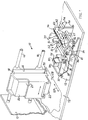
- the numeral 10 indicates a printer having a frame 12 on which a carriage 14 runs backwards and forwards, guided and supported by two guides 16.
- the carriage 14 carries a support 18 designed to hold a module 20 for printing in black, but which is interchangeable alternatively with a similar module for color printing.
- the module 20 consists of an ink jet print head 22 integral with its own ink reservoir 21.
- the module 20 may alternatively be composed of an intermediate support that fits inside the support 18 and carries a print head, and accommodates in turn a removable ink cartridge which connects hydraulically with the head so as to feed it.
- the head 22 carries a plate 24 in which nozzles 26 are formed (Fig. 2), from which drops of ink are expelled towards a printing support 28 (Fig. 1) travelling over the frame 12 in the direction 29.
- the printer 12 includes a service station 30 for the print head 22. It is positioned on the path of this head, at one end of its travel in a service point 32.
- the service station 30 comprises a cleaning part 34, and a device 40 for restoring and protecting the nozzles 26.
- the cleaning part 34 is in the shape of a flexible blade mounted vertically on a trough 36 for collecting the ink removed by the blade 34.
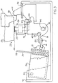
- the trough 36 is hinged to the frame 12 by means of a pin 31, on which the trough 36 can pivot as indicated by the arrow 33.
- the trough is biased upwardly or in an anti-clockwise direction as seen in Fig. 2 by a spring 97, indicated diagrammatically.
- the blade 34 projects above the trough 36 and is positioned perpendicularly to the path of the head 22.
- the blade 34 is of a height such that when the trough 36 is in the rest position, shown in Figs. 1 and 2, the top edge 38 of the blade 34 interferes either with the head 22 for printing in black, or with a head 23 (Fig. 2) for color printing.
- the device 40 for restoring and protecting the nozzles 26 is positioned beyond and in line with the trough 36, in the direction of motion of the carriage 14 towards the position 32.
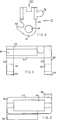
- the device 40 comprises a support 42 (Figs. 4 to 6) capable of independently pivoting and translating axially on a shaft 44 fixed to the frame 12, in the directions of the arrows 45 and 47 respectively (Fig. 1).
- a support 42 (Figs. 4 to 6) capable of independently pivoting and translating axially on a shaft 44 fixed to the frame 12, in the directions of the arrows 45 and 47 respectively (Fig. 1).
- the support 42 (Fig. 5) includes two arms 53 and 55 parallel with each other and each integral at one end with a cross member 57, while another end 59 of each arm is provided with a hole 60 containing the shaft 44.
- a part 46 for collecting the ink purged from the nozzles 26 is mounted on the support 42. It consists of a slide 48 (Fig. 7) surmounted by a cap or cover 50 of soft rubber to protect the nozzles.
- the slide 48 is formed by a body 52 of approximately parallelepidal shape that travels between the arms 53 and 55 of the support 42. An upper portion 62 of the body 52 projects above the support 42 through an aperture 63 (Fig. 6) in the cross member 57. A hole 66 containing the shaft 44 passes through the opposite lower portion 64 of the body 52.
- the upper portion 62 comprises two recesses 68 and 69 side by side and elongate in the direction of the arrow 47, that is perpendicularly to the path of the heads 22 and 23; these recesses are designed to hold the black ink and the colored ink respectively, as will be explained below.
- the recess 69 for the colored ink is longer than the recess 68 for the black ink because the color head 23 has a greater transverse dimension than the black head 22.
- the recess 69 for the colored ink is closed on the underside, while the recess 68 for the black ink is connected by a tube 67 (Figs. 1, 2) to a suction device, not shown in the drawings, for aspirating a certain amount of ink from the nozzles of the head 22 in order to avoid possible coagulation of the black ink, which is more likely to coagulate than the colored ink, given its composition.
- the cap or cover 50 is fixed elastically to the upper portion 62 of the body 52 and is provided with two apertures 70 and 71 over the recesses 68 and 69 respectively.
- the apertures 70 and 71 are surrounded by corresponding projecting and elastically yielding edges 73 designed to conform perfectly with the lower face 25 of the head 22, or alternatively of the head 23, when moved into the service point 32.
- the support 42 and the unit 46 can travel axially along the shaft 44 as a result of a manual action by the operator, from a first position in which the recess 68 and the corresponding aperture 70 in the cap or cover 50 are situated in the path of the head 22 for the black ink, to a second position in which the recess 69 and the corresponding aperture 71 in the cap or cover 50 are situated in the same path when the color head is mounted on the carriage 14.
- the printer in fact generates a signal for the operator indicating whether the black head or color head is mounted on the carriage 14.
- the positioning of the support 42 in each of the two positions is made stable by means of a compression spring 75 housed inside the body 52 (Fig. 7), and a ball 74 engaging selectively with two grooves 65 on the shaft 44. Movement from one position to the other is brought about by means of a rod 77 (Fig. 1) operated by the operator.
- the support 42 (Fig. 2) is connected to the trough 36 by means of a rocker 80 hinged to the frame 12 by pins 81 and having a first arm 82 coupled slidingly with a fork 84 integral with the support 42.
- a second arm 86 of the rocker 80 situated about 180° away from the first arm 82, pivots in a corresponding fork 85 on the trough 36.
- the first arm 82 runs approximately parallel with the longitudinal axis "A" of the rocker 80 in such a way that its edge 83, which forms a guide for the fork 84, is always engaged in the fork as the support 42 is moved in the direction of the arrow 47 (Fig. 1).
- the color head 23 is situated at a level "C" higher than a level “N” of the black head 22, by a predetermined distance "D", as shown in Fig. 2, for example between 0.4mm and 0.6mm, it is necessary, in order to ensure correct cleaning action of the blade 34 on both heads, that the top edge 38 of the blade 34 is pressed against both heads with the same force. This is achieved by keeping the interference between the edge 38 of the blade 34 and each of the heads constant.
- the guide 83 of the rocker 80 (Fig. 9) is inclined by an angle “alpha” ( ⁇ ) of between approximately 3° and 6° with respect to the axis "A" of the rocker 80.
- the guide 83 is subdivided into three portions 87, 88, 89. The endmost portions 87 and 89 run parallel with the axis "A", while the central portion 88, connected continuously with the portions 87 and 89, is inclined at the angle "alpha".
- the rocker 80 with the inclined guide 83 therefore forms a blade setting part, controlled by the axial position assumed by the support 42.
- the angle "alpha” can clearly assume values other than those indicated above depending upon the difference between the levels “C” and “N” and upon the dimensions of the components used in embodiments differing from the preferred embodiment described here.
- the carriage 14 is brought automatically by the printer's logic unit to the service point 32, where, at the end of its travel, a trigger member formed by a tooth 90 on the carriage 14 (Figs. 1 and 2) moves a lever 91 which is coupled slidingly to a rib 94 on the support 42, causing said support to turn in the direction of the arrow 45.
- the lever 91 is prevented from moving transversely, but not from pivoting, by a slot 96 in the frame 12.
- Fig. 3 shows the position adopted by the support 42 and by the trough 36 as a result of the action of the tooth 90.
- the cap 50 presses against, without sliding over, the lower surface 25 of whichever head is fitted at that time.
- the cap or cover 50 is held against the surface 25 by the action of the spring 75 (Fig. 7) which allows the slide part 48 to make small movements relative to the support 42, owing to the elongated shape in section of the hole 66.
- the spring 75 allows the part 48 to adapt to different levels "C" and "N" of different heads.
- the clockwise rotation (Fig. 2) of the support 42 about the shaft 44 causes, by means of the rocker 80, a clockwise rotation of the trough 36 and a consequent lowering of the blade 34 (Fig. 3), which moves away from the surface 25 of the heads after having removed any trace of ink from the surface 25.
- the nozzles are isolated from the external environment, in an atmosphere where the humidity is such that, owing to the low tendency of colored inks to coagulate, they remain efficient for a suitable period of time.
- the service station for an ink jet printer embodying the invention may be modified or have parts added to it without departing from the scope of the invention.
- the print head may be a fixed line-type head and the unit formed by the cleaning part and restoring device may be mounted on a carriage that moves along the head.
Landscapes
- Ink Jet (AREA)
- Common Mechanisms (AREA)
Applications Claiming Priority (2)
| Application Number | Priority Date | Filing Date | Title |
|---|---|---|---|
| ITTO930854A IT1261111B (it) | 1993-11-11 | 1993-11-11 | Stazione di pulizia per una stampante a getto di inchiostro |
| ITTO930854 | 1993-11-11 |
Publications (3)
| Publication Number | Publication Date |
|---|---|
| EP0653306A2 true EP0653306A2 (fr) | 1995-05-17 |
| EP0653306A3 EP0653306A3 (fr) | 1995-09-06 |
| EP0653306B1 EP0653306B1 (fr) | 1998-06-17 |
Family
ID=11411874
Family Applications (1)
| Application Number | Title | Priority Date | Filing Date |
|---|---|---|---|
| EP94307994A Expired - Lifetime EP0653306B1 (fr) | 1993-11-11 | 1994-10-31 | Poste de maintenance pour imprimante par jet d'encre |
Country Status (5)
| Country | Link |
|---|---|
| US (1) | US5644345A (fr) |
| EP (1) | EP0653306B1 (fr) |
| JP (1) | JP3553662B2 (fr) |
| DE (1) | DE69411124T2 (fr) |
| IT (1) | IT1261111B (fr) |
Cited By (7)
| Publication number | Priority date | Publication date | Assignee | Title |
|---|---|---|---|---|
| EP0744294A1 (fr) * | 1995-05-25 | 1996-11-27 | Seiko Epson Corporation | Dispositif de recouvrement pour une tête d'impression à jet d'encre |
| EP0728585A3 (fr) * | 1995-02-22 | 1997-03-19 | Ocd Sa | Imprimante à jet d'encre avec station de maintenance |
| EP0719645A3 (fr) * | 1994-12-30 | 1997-03-19 | Ocd Sa | Imprimante à jet d'encre |
| EP0850773A3 (fr) * | 1996-11-22 | 1999-07-21 | Seiko Epson Corporation | Appareil d'enregistrement à jet d'encre |
| EP0845360A3 (fr) * | 1996-11-29 | 1999-07-21 | Seiko Epson Corporation | Dispositif de fermeture et appareil d'enregistrement à jet d'encre l'utilisant |
| EP1238807A1 (fr) * | 2001-03-09 | 2002-09-11 | Hewlett-Packard Company | Station d'entretien améliorée pour imprimante à jet d'encre |
| EP1354707A3 (fr) * | 2002-04-19 | 2003-12-10 | Brother Kogyo Kabushiki Kaisha | Appareil de nettoyage pour tête d'impression à jets d'encre |
Families Citing this family (16)
| Publication number | Priority date | Publication date | Assignee | Title |
|---|---|---|---|---|
| DE69631741T2 (de) * | 1995-07-31 | 2005-03-17 | Hewlett-Packard Co. (N.D.Ges.D.Staates Delaware), Palo Alto | Instandsetzungsstelle mit translatorischer Bewegung für Farbstrahldruckköpfe |
| US5745133A (en) * | 1995-10-31 | 1998-04-28 | Hewlett-Packard Company | Dual pivoting wiper system for inkjet printheads |
| JPH09141884A (ja) * | 1995-11-16 | 1997-06-03 | Brother Ind Ltd | インクジェットプリンタ |
| KR200151934Y1 (ko) * | 1996-03-28 | 1999-07-15 | 윤종용 | 잉크젯프린터의 서어비스 스테이션장치 |
| AU132828S (en) * | 1997-03-03 | 1998-02-09 | Hewlett Packard Co | Printhead service station unit |
| JP2972667B2 (ja) * | 1997-08-11 | 1999-11-08 | 新潟日本電気株式会社 | インクジェット記録装置 |
| USD430600S (en) * | 1999-02-18 | 2000-09-05 | Hewlett-Packard Company | Printhead service station unit |
| US6250736B1 (en) * | 1999-08-04 | 2001-06-26 | Eastman Kodak Company | Continuous ink jet print head with fixed position ink gutter compatible with hydrodynamic and wipe cleaning |
| US6755503B2 (en) * | 2001-02-23 | 2004-06-29 | Mailroom Technology, Inc. | Housekeeping station |
| JP2002337415A (ja) * | 2001-03-15 | 2002-11-27 | Canon Inc | キャリッジを備える装置 |
| JP2004130299A (ja) | 2002-08-02 | 2004-04-30 | Seiko Epson Corp | 液滴吐出装置、電気光学装置の製造方法、電気光学装置および電子機器 |
| GB2394445B (en) * | 2002-10-22 | 2005-12-07 | Hewlett Packard Co | Printhead service station |
| CA2601061A1 (fr) * | 2005-03-11 | 2006-09-21 | Tonerhead, Inc. | Methode et appareil de controle de cartouches d'imprimantes |
| US7665819B2 (en) * | 2005-04-21 | 2010-02-23 | Tonerhead, Inc. | Method and apparatus for a printer cartridge tester |
| TWI317699B (en) * | 2006-12-25 | 2009-12-01 | Ind Tech Res Inst | Device and method for removing residues |
| US8434854B1 (en) * | 2011-10-19 | 2013-05-07 | Xerox Corporation | System for ink removal from a printhead assembly |
Family Cites Families (5)
| Publication number | Priority date | Publication date | Assignee | Title |
|---|---|---|---|---|
| JPH0326546U (fr) * | 1989-07-25 | 1991-03-18 | ||
| US5103244A (en) * | 1990-07-05 | 1992-04-07 | Hewlett-Packard Company | Method and apparatus for cleaning ink-jet printheads |
| US5155497A (en) * | 1991-07-30 | 1992-10-13 | Hewlett-Packard Company | Service station for ink-jet printer |
| US5394178A (en) * | 1992-12-21 | 1995-02-28 | Hewlett-Packard Company | Printhead servicing apparatus with pivotal servicing lever |
| US5563637A (en) * | 1993-10-26 | 1996-10-08 | Lexmark International, Inc. | Maintenance station for ink jet printhead |
-
1993
- 1993-11-11 IT ITTO930854A patent/IT1261111B/it active IP Right Grant
-
1994
- 1994-10-26 US US08/329,164 patent/US5644345A/en not_active Expired - Lifetime
- 1994-10-31 DE DE69411124T patent/DE69411124T2/de not_active Expired - Lifetime
- 1994-10-31 EP EP94307994A patent/EP0653306B1/fr not_active Expired - Lifetime
- 1994-11-10 JP JP27658594A patent/JP3553662B2/ja not_active Expired - Lifetime
Cited By (15)
| Publication number | Priority date | Publication date | Assignee | Title |
|---|---|---|---|---|
| EP0719645A3 (fr) * | 1994-12-30 | 1997-03-19 | Ocd Sa | Imprimante à jet d'encre |
| US5790148A (en) * | 1994-12-30 | 1998-08-04 | Ocd Sa | Insertable printer head cap for an ink jet printer |
| EP0728585A3 (fr) * | 1995-02-22 | 1997-03-19 | Ocd Sa | Imprimante à jet d'encre avec station de maintenance |
| US5748205A (en) * | 1995-02-22 | 1998-05-05 | Ocd S.A. | Inkjet printer |
| EP0744294A1 (fr) * | 1995-05-25 | 1996-11-27 | Seiko Epson Corporation | Dispositif de recouvrement pour une tête d'impression à jet d'encre |
| US6286931B1 (en) | 1996-11-22 | 2001-09-11 | Seiko Epson Corporation | Ink jet recording apparatus |
| EP0850773A3 (fr) * | 1996-11-22 | 1999-07-21 | Seiko Epson Corporation | Appareil d'enregistrement à jet d'encre |
| EP1167041A1 (fr) * | 1996-11-22 | 2002-01-02 | Seiko Epson Corporation | Appareil d'enregistrement à jet d'encre |
| EP0845360A3 (fr) * | 1996-11-29 | 1999-07-21 | Seiko Epson Corporation | Dispositif de fermeture et appareil d'enregistrement à jet d'encre l'utilisant |
| US6273546B1 (en) | 1996-11-29 | 2001-08-14 | Seiko Epson Corporation | Capping unit having a decreased load during a peeling operation and ink-jet recording apparatus using the same |
| US6286930B1 (en) | 1996-11-29 | 2001-09-11 | Seiko Epson Corporation | Capping unit and ink-jet recording apparatus using the same |
| EP1238807A1 (fr) * | 2001-03-09 | 2002-09-11 | Hewlett-Packard Company | Station d'entretien améliorée pour imprimante à jet d'encre |
| US6533388B2 (en) | 2001-03-09 | 2003-03-18 | Hewlett-Packard Company | Service station for an inkjet printer |
| EP1354707A3 (fr) * | 2002-04-19 | 2003-12-10 | Brother Kogyo Kabushiki Kaisha | Appareil de nettoyage pour tête d'impression à jets d'encre |
| US6886907B1 (en) | 2002-04-19 | 2005-05-03 | Brother Kogyo Kabushiki Kaisha | Cleaning device for cleaning printhead of ink-jet printer |
Also Published As
| Publication number | Publication date |
|---|---|
| DE69411124T2 (de) | 1999-02-25 |
| EP0653306A3 (fr) | 1995-09-06 |
| DE69411124D1 (de) | 1998-07-23 |
| US5644345A (en) | 1997-07-01 |
| JP3553662B2 (ja) | 2004-08-11 |
| JPH07186399A (ja) | 1995-07-25 |
| IT1261111B (it) | 1996-05-09 |
| ITTO930854A1 (it) | 1995-05-11 |
| EP0653306B1 (fr) | 1998-06-17 |
| ITTO930854A0 (it) | 1993-11-11 |
Similar Documents
| Publication | Publication Date | Title |
|---|---|---|
| US5644345A (en) | Service station for ink jet printer | |
| US5097276A (en) | Ink jet head capping device | |
| US6174041B1 (en) | Modular printhead service station with self-contained motorized components | |
| DE69509942T2 (de) | Schutzkappe für einen Tintenstrahlschreiber | |
| EP0526061B1 (fr) | Poste de maintenance pour imprimante à jet d'encre | |
| EP0526014B1 (fr) | Onde mobile d'une tête d'impression pour imprimantes à jet d'encre | |
| US6106098A (en) | Ink jet recording apparatus having respective capping members for plural recording heads | |
| US5627573A (en) | Maintenance device in an ink jet printing apparatus | |
| CN1216268A (zh) | 喷墨记录装置 | |
| EP0720913B1 (fr) | Dispositif d'entretien dans un appareil d'impression à jet d'encre | |
| JP3819223B2 (ja) | インクジェットプリントヘッドのクリーニング用溝付きチップ形ワイパー | |
| US6981756B2 (en) | Apparatus and method for placing fluid droplets onto an object | |
| JP3317020B2 (ja) | インクジェット記録装置 | |
| US4947747A (en) | Hand-held labeling device with pivotally mounted front plate | |
| US6464326B1 (en) | Wiping apparatus for an ink cartridge | |
| EP0700784A1 (fr) | Appareil d'enregistrement par jet d'encre | |
| JPH1016316A (ja) | 印字装置 | |
| CN215096443U (zh) | 一种具有废墨收集功能的喷墨打印机 | |
| US6755504B2 (en) | Independent wiping of printhead | |
| JP7225913B2 (ja) | 印刷装置 | |
| JP3345758B2 (ja) | インクジェット記録装置 | |
| US5872578A (en) | Capping device for ink jet head in ink jet printer | |
| JP2002019151A (ja) | インクジェット画像形成装置 | |
| JPH05138877A (ja) | インクジエツトプリンタ | |
| JPH081954A (ja) | インクジェット記録装置 |
Legal Events
| Date | Code | Title | Description |
|---|---|---|---|
| PUAI | Public reference made under article 153(3) epc to a published international application that has entered the european phase |
Free format text: ORIGINAL CODE: 0009012 |
|
| AK | Designated contracting states |
Kind code of ref document: A2 Designated state(s): DE FR GB |
|
| PUAL | Search report despatched |
Free format text: ORIGINAL CODE: 0009013 |
|
| AK | Designated contracting states |
Kind code of ref document: A3 Designated state(s): DE FR GB |
|
| 17P | Request for examination filed |
Effective date: 19951222 |
|
| 17Q | First examination report despatched |
Effective date: 19961106 |
|
| GRAG | Despatch of communication of intention to grant |
Free format text: ORIGINAL CODE: EPIDOS AGRA |
|
| GRAG | Despatch of communication of intention to grant |
Free format text: ORIGINAL CODE: EPIDOS AGRA |
|
| GRAH | Despatch of communication of intention to grant a patent |
Free format text: ORIGINAL CODE: EPIDOS IGRA |
|
| GRAH | Despatch of communication of intention to grant a patent |
Free format text: ORIGINAL CODE: EPIDOS IGRA |
|
| GRAA | (expected) grant |
Free format text: ORIGINAL CODE: 0009210 |
|
| AK | Designated contracting states |
Kind code of ref document: B1 Designated state(s): DE FR GB |
|
| REF | Corresponds to: |
Ref document number: 69411124 Country of ref document: DE Date of ref document: 19980723 |
|
| ET | Fr: translation filed | ||
| REG | Reference to a national code |
Ref country code: GB Ref legal event code: 732E |
|
| REG | Reference to a national code |
Ref country code: FR Ref legal event code: TP |
|
| RAP2 | Party data changed (patent owner data changed or rights of a patent transferred) |
Owner name: OLIVETTI LEXIKON S.P.A. |
|
| PLBE | No opposition filed within time limit |
Free format text: ORIGINAL CODE: 0009261 |
|
| STAA | Information on the status of an ep patent application or granted ep patent |
Free format text: STATUS: NO OPPOSITION FILED WITHIN TIME LIMIT |
|
| 26N | No opposition filed | ||
| REG | Reference to a national code |
Ref country code: GB Ref legal event code: IF02 |
|
| PGFP | Annual fee paid to national office [announced via postgrant information from national office to epo] |
Ref country code: GB Payment date: 20131028 Year of fee payment: 20 Ref country code: FR Payment date: 20131017 Year of fee payment: 20 Ref country code: DE Payment date: 20131029 Year of fee payment: 20 |
|
| REG | Reference to a national code |
Ref country code: DE Ref legal event code: R071 Ref document number: 69411124 Country of ref document: DE |
|
| REG | Reference to a national code |
Ref country code: DE Ref legal event code: R071 Ref document number: 69411124 Country of ref document: DE |
|
| REG | Reference to a national code |
Ref country code: GB Ref legal event code: PE20 Expiry date: 20141030 |
|
| PG25 | Lapsed in a contracting state [announced via postgrant information from national office to epo] |
Ref country code: GB Free format text: LAPSE BECAUSE OF EXPIRATION OF PROTECTION Effective date: 20141030 |