EP0653523A2 - Toilette notamment toilette portative - Google Patents
Toilette notamment toilette portative Download PDFInfo
- Publication number
- EP0653523A2 EP0653523A2 EP94117791A EP94117791A EP0653523A2 EP 0653523 A2 EP0653523 A2 EP 0653523A2 EP 94117791 A EP94117791 A EP 94117791A EP 94117791 A EP94117791 A EP 94117791A EP 0653523 A2 EP0653523 A2 EP 0653523A2
- Authority
- EP
- European Patent Office
- Prior art keywords
- slide
- valve
- opening
- ring
- toilet
- Prior art date
- Legal status (The legal status is an assumption and is not a legal conclusion. Google has not performed a legal analysis and makes no representation as to the accuracy of the status listed.)
- Withdrawn
Links
Images

Classifications
-
- B—PERFORMING OPERATIONS; TRANSPORTING
- B63—SHIPS OR OTHER WATERBORNE VESSELS; RELATED EQUIPMENT
- B63B—SHIPS OR OTHER WATERBORNE VESSELS; EQUIPMENT FOR SHIPPING
- B63B29/00—Accommodation for crew or passengers not otherwise provided for
- B63B29/02—Cabins or other living spaces; Construction or arrangement thereof
- B63B29/14—Closet or like flushing arrangements; Washing or bathing facilities peculiar to ships
-
- B—PERFORMING OPERATIONS; TRANSPORTING
- B60—VEHICLES IN GENERAL
- B60R—VEHICLES, VEHICLE FITTINGS, OR VEHICLE PARTS, NOT OTHERWISE PROVIDED FOR
- B60R15/00—Arrangements or adaptations of sanitation devices
- B60R15/04—Toilet facilities
-
- E—FIXED CONSTRUCTIONS
- E03—WATER SUPPLY; SEWERAGE
- E03D—WATER-CLOSETS OR URINALS WITH FLUSHING DEVICES; FLUSHING VALVES THEREFOR
- E03D5/00—Special constructions of flushing devices, e.g. closed flushing system
- E03D5/012—Special constructions of flushing devices, e.g. closed flushing system combined with movable closure elements in the bowl outlet
-
- F—MECHANICAL ENGINEERING; LIGHTING; HEATING; WEAPONS; BLASTING
- F16—ENGINEERING ELEMENTS AND UNITS; GENERAL MEASURES FOR PRODUCING AND MAINTAINING EFFECTIVE FUNCTIONING OF MACHINES OR INSTALLATIONS; THERMAL INSULATION IN GENERAL
- F16K—VALVES; TAPS; COCKS; ACTUATING-FLOATS; DEVICES FOR VENTING OR AERATING
- F16K3/00—Gate valves or sliding valves, i.e. cut-off apparatus with closing members having a sliding movement along the seat for opening and closing
- F16K3/30—Details
- F16K3/314—Forms or constructions of slides; Attachment of the slide to the spindle
Definitions
- the invention relates to a toilet, in particular a portable toilet, according to the preamble of claim 1.
- the seal that comes into contact with the underside of the slide is particularly at risk because the underside is washed by the faeces when the slide is closed, so that this underside remains contaminated after the receptacle has been emptied, as a result of which the sealing lips are particularly stressed.
- the object of the invention is therefore to improve the toilet of the type mentioned above so that the seal of the slide valve lasts much longer and the usability of the toilet is significantly increased.
- valve slide is designed as a slide-through slide, which has an opening part and a closing part in its slide plate, which can be pushed in succession under the drain opening.
- the slide plate is also provided with an opening part which represents an extension of the closing part, i.e. in is on the same level as the latter, with the result that the sealing rings are in constant contact with the slide surface irrespective of whether the toilet is in the operating state, that is to say the drain opening is open or is closed by closing the slide.
- the sealing rings therefore do not need to be pushed apart by the slide each time the toilet is started up in order to bring them into contact with the surface of the slide. As a result, the sealing rings are stressed considerably less and therefore wear out less quickly.
- the valve housing surrounding the slide consists of an upper housing part and a lower housing part, which can be connected tightly to one another and each have an opening, which lie congruently one above the other and correspond to the opening in the opening part of the slide plate.
- the openings can be surrounded by ring flanges which have multi-part sealing arrangements for sealing the slide-through slide in the closed state and for sealing the drain opening in the seat part and the inlet opening in the receptacle of the toilet.
- the sealing device for the valve housing upper part having the ring flange has an S-shaped, elastic ring seal on its lower lip when the valve is closed is in sealing contact with the surface of the closing part of the valve slide and its upper lip is clamped between the ring flange and an approximately S-shaped, solid ring body of the sealing device, onto which, in turn, a clamping ring of the sealing device can be placed, between itself and the ring body clamps an O-ring seal to seal a cylindrical wall piece delimiting the inlet opening of the seat part.
- the sealing device belonging to the lower valve housing can expediently be provided with an S-shaped, profiled, elastic ring seal which corresponds to the profiled ring seal of the sealing device for the valve housing upper part, and that the S-shaped ring seal in the installed state of the sealing device and in The closed position of the valve slide rests with its lower lip on the lower surface of the closing part and is thereby surrounded by the ring flange of the opening of the lower valve housing part, while in the closed position the S-shaped ring seal rests with its upper lip on the ring flange of a cylindrical tube piece belonging to the sealing device, which is located at the upper end of the pipe section that clamps the profiled ring seal when the sealing device is installed.
- the outer surface of this pipe section can be provided with cams which engage in recesses in the edge of the edge of the inlet opening of the receptacle that match them.
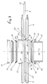
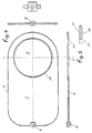
- the valve slide 18 shown in FIGS. 1-5 has an opening part 6 and a closing part 7, which are arranged one behind the other in the slide plate 5 and can therefore be pushed successively under the drain opening 25 of the partially shown seat part 1 of the portable toilet, around which the faecal passage passes to open or close the valve controlling the seat part 1 into the receptacle 2.
- valve slide 18 is arranged in a flat valve housing 40, consisting of an upper housing part 3 and a lower housing part 4, which are tightly connected to one another and lie congruently one above the other and correspond to the opening 24 (FIG. 3) in the opening part 6 of the slide plate 5.
- valve spool 18 is in the position shown in FIG. 1 in the closed position, ie its closing part 7 blocks the flow of feces from the seat part 1 into the receptacle 2.
- An actuating rod 9 serves to open the valve spool, which is on one of them End 20 is connected by a coupling device 8, 10 to the slide plate 5 and at its other end 21 to a handle part 19, with the aid of which the slide plate is moved back and forth.
- the openings 22 and 23 in the valve housing upper part 3 and lower part 4 are surrounded by ring flanges 17, 16, the multi-part sealing arrangements 11, 12, 13, 14, 15 for sealing the slide-through slide 18 in the closed state and for sealing the drain opening 25 in the seat part 1 and the inlet opening 26 in the receptacle 2 of the toilet.
- the openings 22, 23 are equipped with ring flanges 27, 28 which guide the slide plate 5 in a straight line when the valve slide is moved back and forth by forming a guide gap between them through which the slide plate can slide , as can be seen from Fig. 1.
- the seal arrangement 11, 12, 13 for the valve housing upper part 3 having the ring flange 17 has, as shown in FIG. 3, an S-shaped, elastic ring seal 13 which is provided with a lower lip 29 and an upper lip 30.
- the lower lip 29 is in sealing contact with the surface 31 of the closing part 7 of the valve slide 18.
- the upper lip 30 is clamped between the ring flange 27 of the upper housing part 3 and an approximately S-shaped profiled, fixed ring body 12 of this sealing device.
- a clamping ring 11 can be placed on this ring body 12, which includes an O-ring seal 32 between it and the ring body 12, which seal to seal an inlet opening 25 of the seat part 1, serves cylindrical wall piece 32, which is inserted into the valve slide from above when the seat part 1 is fastened to the receptacle 2, for example by clips, not shown, attached to them laterally.
- the sealing device belonging to the lower valve housing part 4 also has an S-shaped profiled, elastic ring seal 14 which corresponds to the profiled ring seal 13 and in the installed state of the sealing device and in the closed position of the valve slide 18 with its lower lip 34 on the lower surface 36 of the closing part 7 1, and is surrounded by the annular flange 28 of the opening 23 of the valve housing lower part 4.
- the upper lip 35 of the ring seal 14 lies in the closed position on the ring flange 44 of a cylindrical tube piece 15 belonging to the sealing device.
- the ring flange is located at the upper end of the pipe section which clamps the profiled ring seal 14 when the sealing device is in the installed state.
- the outer surface of the pipe section 15 is provided with cams 37 which engage in matching recesses in the edge 38 of the inlet opening 39 of the receiving container 2, so that there is a firm connection between the sealing device for the valve housing lower part 4 and the receiving container 2.
- the annular flange 16 of the lower valve housing part 4 engages in an annular groove 42 of the annular flange 44 at the upper end of the pipe section 15, as a result of which the valve housing is securely anchored on the receptacle.
- the O-ring seal 43 serves to seal between the edge 38 of the inlet opening 39 and the cylindrical tube piece 15.
- the entire toilet including the valve housing 4 and the sealing devices 11, 12, 13, 14, 15 is made of plastic. Since the diameter of the opening 24 in the opening part 6 is smaller than the inner diameter of the ring seals 13 and 14, the sealing lips 34 and 29 facing the lower surface 36 and the upper surface 31 of the slide plate 5 lie not only on the named surfaces of the opening part 6 but also of the closing part 7, which means that the opposite sealing lips are kept apart from one another by the slide plate 5 and are kept in sealing contact with the two surfaces. This avoids that these sealing lips are stressed too much when the valve spool is pushed back and forth, since they do not have to be pressed apart, as is the case with valve spools which have only one closing part.
- the careful treatment of the two ring seals 13 and 14 is served by the fact that the opening 24 in the opening part 6 is circular and has a rounded edge 41 tapering conically towards the center of the circle, since this causes faecal matter to get caught on the edge is largely avoided, which could otherwise lead to contamination of the seal.
Landscapes
- Engineering & Computer Science (AREA)
- Mechanical Engineering (AREA)
- General Engineering & Computer Science (AREA)
- Public Health (AREA)
- Health & Medical Sciences (AREA)
- Life Sciences & Earth Sciences (AREA)
- Aviation & Aerospace Engineering (AREA)
- Ocean & Marine Engineering (AREA)
- Chemical & Material Sciences (AREA)
- Hydrology & Water Resources (AREA)
- Combustion & Propulsion (AREA)
- Water Supply & Treatment (AREA)
- Epidemiology (AREA)
- General Health & Medical Sciences (AREA)
- Organic Low-Molecular-Weight Compounds And Preparation Thereof (AREA)
- Toilet Supplies (AREA)
Applications Claiming Priority (2)
| Application Number | Priority Date | Filing Date | Title |
|---|---|---|---|
| DE9317560U DE9317560U1 (de) | 1993-11-16 | 1993-11-16 | Toilette, insbesondere tragbare Toilette |
| DE9317560U | 1993-11-16 |
Publications (2)
| Publication Number | Publication Date |
|---|---|
| EP0653523A2 true EP0653523A2 (fr) | 1995-05-17 |
| EP0653523A3 EP0653523A3 (fr) | 1996-04-17 |
Family
ID=6900791
Family Applications (1)
| Application Number | Title | Priority Date | Filing Date |
|---|---|---|---|
| EP94117791A Withdrawn EP0653523A3 (fr) | 1993-11-16 | 1994-11-10 | Toilette notamment toilette portative. |
Country Status (2)
| Country | Link |
|---|---|
| EP (1) | EP0653523A3 (fr) |
| DE (1) | DE9317560U1 (fr) |
Family Cites Families (4)
| Publication number | Priority date | Publication date | Assignee | Title |
|---|---|---|---|---|
| US3333814A (en) * | 1964-11-17 | 1967-08-01 | Thetford Engineering Corp | Wedge gate valve assembly |
| US3801991A (en) * | 1972-11-29 | 1974-04-09 | Mansfield Sanitary Inc | Portable, self-contained toilet |
| GB2095370A (en) * | 1981-03-25 | 1982-09-29 | Thompson Edward Ltd | Gas main shut-off valve |
| GB2263533A (en) * | 1992-01-24 | 1993-07-28 | Hodge Clemco Ltd | Metering valve |
-
1993
- 1993-11-16 DE DE9317560U patent/DE9317560U1/de not_active Expired - Lifetime
-
1994
- 1994-11-10 EP EP94117791A patent/EP0653523A3/fr not_active Withdrawn
Also Published As
| Publication number | Publication date |
|---|---|
| DE9317560U1 (de) | 1994-01-27 |
| EP0653523A3 (fr) | 1996-04-17 |
Similar Documents
| Publication | Publication Date | Title |
|---|---|---|
| DE3242947A1 (de) | Doppelsitzventil mit zwei ventiltellern | |
| DE10302508B4 (de) | Spüleinheit für eine Toilette | |
| DE60111782T2 (de) | Siphonspülvorrichtung | |
| DE2311284A1 (de) | Ventilanordnung zum rueckspulen von luft- oder gasfiltern | |
| DE69211321T2 (de) | Tragbarer Abfallbehälter mit verbesserter Einlassventilanordnung | |
| CH654089A5 (de) | Mischventil fuer eine mischbatterie. | |
| DE19722615A1 (de) | Leckagefrei schaltendes Doppelsitzventil | |
| EP0653523A2 (fr) | Toilette notamment toilette portative | |
| DE9101804U1 (de) | Vorrichtung zum Reinigen von Rohren und Kanälen und zum Stauen oder Umleiten von Wasser in Rohren und Kanälen | |
| WO1998055706A1 (fr) | Systeme de toilettes a aspiration par le vide | |
| EP3708724A1 (fr) | Dispositif d'écoulement avec trop-plein | |
| DE2832499A1 (de) | Toilette | |
| DE3243066A1 (de) | Sinkkasten mit rueckstau-doppelverschluss | |
| DE102004001155B4 (de) | Uriniervorrichtung zur Anbringung an einer eine Toilettenbrille und/oder einen Toilettendeckel aufweisenden Toilettenschüssel | |
| EP4520887B1 (fr) | Bouche d'égout avec piège à odeurs | |
| DE2635923C3 (de) | Muffenventil | |
| DE3744490A1 (de) | Dichtung fuer eine einfuelloeffnung von einer in sich geschlossenen sanitaereinrichtung | |
| DE2558642A1 (de) | Reinigungsrohr | |
| EP2101000B1 (fr) | Bouche d'incendie | |
| DE2452786C2 (de) | Rückstau- und Schließventil für Flüssigkeitsabläufe | |
| DE29923799U1 (de) | Doppelsitzventil mit spülfähiger Ventilstangendurchführung am Ventilgehäuse | |
| DE202025105117U1 (de) | Vorrichtung zum geruchsdichten Verschließen einer Abflussleitung eines wasserlosen Urinals | |
| EP0653521A2 (fr) | Toilette, notamment toilette portative pour les bateaux, les caravanes ou les camping-cars | |
| DE2312681A1 (de) | Verfahren und vorrichtung zur freilegung einer verstopften abflussleitung | |
| EP0682966B1 (fr) | Fermeture à action automatique |
Legal Events
| Date | Code | Title | Description |
|---|---|---|---|
| PUAI | Public reference made under article 153(3) epc to a published international application that has entered the european phase |
Free format text: ORIGINAL CODE: 0009012 |
|
| AK | Designated contracting states |
Kind code of ref document: A2 Designated state(s): AT BE CH DE ES FR GB IT LI NL PT |
|
| PUAL | Search report despatched |
Free format text: ORIGINAL CODE: 0009013 |
|
| AK | Designated contracting states |
Kind code of ref document: A3 Designated state(s): AT BE CH DE ES FR GB IT LI NL PT |
|
| 17P | Request for examination filed |
Effective date: 19960814 |
|
| RAP1 | Party data changed (applicant data changed or rights of an application transferred) |
Owner name: CAMPING GAZ (DEUTSCHLAND) GMBH |
|
| STAA | Information on the status of an ep patent application or granted ep patent |
Free format text: STATUS: THE APPLICATION IS DEEMED TO BE WITHDRAWN |
|
| 18D | Application deemed to be withdrawn |
Effective date: 19990601 |