EP0653569A1 - Ferrure pour l'assemblage d'éléments de construction jointifs - Google Patents
Ferrure pour l'assemblage d'éléments de construction jointifs Download PDFInfo
- Publication number
- EP0653569A1 EP0653569A1 EP94115247A EP94115247A EP0653569A1 EP 0653569 A1 EP0653569 A1 EP 0653569A1 EP 94115247 A EP94115247 A EP 94115247A EP 94115247 A EP94115247 A EP 94115247A EP 0653569 A1 EP0653569 A1 EP 0653569A1
- Authority
- EP
- European Patent Office
- Prior art keywords
- base
- housing
- latching
- locking
- furniture
- Prior art date
- Legal status (The legal status is an assumption and is not a legal conclusion. Google has not performed a legal analysis and makes no representation as to the accuracy of the status listed.)
- Withdrawn
Links
Images

Classifications
-
- F—MECHANICAL ENGINEERING; LIGHTING; HEATING; WEAPONS; BLASTING
- F16—ENGINEERING ELEMENTS AND UNITS; GENERAL MEASURES FOR PRODUCING AND MAINTAINING EFFECTIVE FUNCTIONING OF MACHINES OR INSTALLATIONS; THERMAL INSULATION IN GENERAL
- F16B—DEVICES FOR FASTENING OR SECURING CONSTRUCTIONAL ELEMENTS OR MACHINE PARTS TOGETHER, e.g. NAILS, BOLTS, CIRCLIPS, CLAMPS, CLIPS OR WEDGES; JOINTS OR JOINTING
- F16B12/00—Jointing of furniture or the like, e.g. hidden from exterior
- F16B12/10—Jointing of furniture or the like, e.g. hidden from exterior using pegs, bolts, tenons, clamps, clips, or the like
- F16B12/12—Jointing of furniture or the like, e.g. hidden from exterior using pegs, bolts, tenons, clamps, clips, or the like for non-metal furniture parts, e.g. made of wood, of plastics
- F16B12/14—Jointing of furniture or the like, e.g. hidden from exterior using pegs, bolts, tenons, clamps, clips, or the like for non-metal furniture parts, e.g. made of wood, of plastics using threaded bolts or screws
-
- A—HUMAN NECESSITIES
- A47—FURNITURE; DOMESTIC ARTICLES OR APPLIANCES; COFFEE MILLS; SPICE MILLS; SUCTION CLEANERS IN GENERAL
- A47B—TABLES; DESKS; OFFICE FURNITURE; CABINETS; DRAWERS; GENERAL DETAILS OF FURNITURE
- A47B2230/00—Furniture jointing; Furniture with such jointing
- A47B2230/02—Assembly systems with separate fixing devices on each corner wall and a common corner joining element
Definitions
- the invention relates to a fitting for connecting abutting construction elements, in particular plate-shaped or beam-shaped elements for furniture, with at least one base and at least one housing, the base being connected to one element and the housing to the other element, and wherein the base and the housing can be locked together.
- furniture edge fittings are used for this purpose, which are composed of a base and a housing.
- the base is first connected to one and the housing to the other of the furniture elements to be connected. Then the two furniture elements are put together according to the desired mounting position.
- the housing of the fitting attached to one furniture element is placed over the base attached to the other furniture element.
- Corresponding catches and counter-catches of the fitting parts create a temporary connection between the housing and the base and thus enable the respective associated furniture elements to be temporarily fixed and aligned.
- the housing is finally screwed to the base.
- the base must firstly be able to absorb the loads acting on the connection of the furniture elements via the connection to the housing and to introduce them into the furniture element assigned to it.
- the locking elements of the base must be sufficiently elastic in order to be able to ensure an effective positive connection of the fitting parts after the housing has been slipped on with its counter-locking.
- stainless steel bases in particular spring steel, are therefore used.
- Stainless steel is a high-quality material, the processing of which requires a relatively large amount of effort.
- the production of bases for furniture edge fittings is correspondingly high associated costs. Especially against the background that furniture edge fittings, for example in the case of shelving systems, are required in large numbers, stainless steel bases represent a noteworthy cost factor.
- the invention is based on the object of creating a fitting which allows a stable connection of the relevant furniture elements and can be produced with little effort.
- the base has at least one holding part and at least one locking part which can be connected to it, and the base is connected to the associated element by means of the holding part and can be locked to the housing by means of the locking part.
- the two-part design divides the base into two functional elements that can be designed according to the tasks assigned to them.
- the holding part thus serves to transmit the loads acting on the connection of the relevant furniture elements.
- the associated requirements can be met, for example, by the choice of the material and / or by the shape of the holding part.
- the requirements for the locking part which must be elastically deformable, can be taken into account.
- the component separation of functions on the base opens up the possibility of using high-quality and therefore expensive materials on the fitting part only where they are actually required due to their function.
- the locking part is advantageously made of plastic. Locking parts made of plastic can be manufactured, for example, by injection molding in large quantities with little manufacturing technology and with little financial outlay. With a corresponding choice of plastic, the latching part also has sufficient elastic properties that enable it to create an effective connection with the counter-latches of the slipped-on housing.
- the holding part of the base expediently consists of metal. In its assembly position, the holding part is primarily subject to tensile and compressive loads. However, relatively low-value and therefore inexpensive metallic materials are suitable for their inclusion. The holding part does not require spring-elastic properties.
- the latching part has a base body and at least one latching element, the latching part on the base body being connectable to the holding part and being latchable by means of the latching element with at least one counter-latching of the housing.
- the base body on which the connection of the latching part to the holding part is produced, can be designed to be stronger in order to absorb the connecting forces.
- the basic body does not require elastic behavior.
- the locking elements of the locking part can be designed constructively so that they have the elastic properties required for locking with the housing.
- the latching part has two latching arms as latching elements and, with these in the installed position, projects laterally beyond the holding part on opposite sides.
- the locking elements are designed to be permanently elastic.
- the holding part is designed as a profile with a substantially U-shaped cross section and engages around the locking part in the installed position on three sides on corresponding counter surfaces.
- the holding part and the locking part can be locked together.
- the holding part and the latching part can be screwed together.
- the locking part connected to the holding part is supported on the holding part with play parallel to the surface of the assigned element.
- the housing can expediently be connected to the base by means of a screw connection on the latching part which is displaceable relative to the holding part.
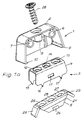
- a fitting 1 which consists of a housing 2 and a base 3.
- the base 3 is composed of a holding profile 4 serving as a holding part and a locking part 5.
- the housing 2 of the fitting 1 shown, like the locking part 5, is made of plastic; the holding profile 4 is made of sheet metal.
- the housing 2 is open on two sides and has threaded sleeves 6, 7, 8 on its inner walls. Locking webs 9, 10 are formed on the flanks of the housing 2.
- the holding profile 4 of the base 3 has a U-shaped cross section.
- locking openings 11 are provided, of which in FIGS. 1a to 1c due to the selected perspective, only a latching opening can be seen.
- the web surface of the holding profile 4 connecting the leg surfaces has mounting bores 12, 13, 14.
- Two claws are formed on the sides of the leg surfaces facing away from the web surface, one of which is shown in FIGS. 1a to 1c three claws 15, 16, 17 are shown.
- the locking part 5 of the base 3 has a base body 21 and locking arms 22, 23 arranged laterally thereon.
- the base body 21 of the locking part 5 also has a U-shaped cross section.
- a locking lug 24 is formed on each of the trapezoidal leg surfaces of the base body 21.
- the land surface of the base body 21 has three mounting holes 25, 26, 27.
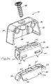
- the mounting profile 4 is first pushed onto the locking part 5 during assembly.
- the latching part 5 snaps with its latching lugs 24 into the latching openings 11 of the holding profile 4 provided for this purpose.
- the holding profile 4 engages around the latching part 5 on the leg surfaces and on the web surface.
- the mounting holes 12, 13, 14 of the holding profile 4 are aligned in this position with the respectively assigned mounting holes 25, 26, 27 of the locking part 5.
- the locking arms 22, 23 of the locking part 5 protrude laterally from the holding profile 4.
- the entire base 3 is placed on the furniture plate, not shown, assigned to it, aligned and screwed to the furniture plate through the mounting holes 12, 25 and 13, 27.
- the fastening screws are tightened, the base 3 digs into the furniture plate with the claws 15, 16, 17 and is thus secured against displacement parallel to the surface of the furniture plate.
- the fastening screws connecting the base 3 to the furniture plate serve at the same time as additional connecting elements between the locking part 5 and the holding profile 4.
- the housing 2 is screwed via the threaded sleeves 6, 7, 8 to the associated furniture plate, also not shown.
- the two furniture panels to be joined together are then attached to one another in accordance with the desired installation position.
- the housing 2 is placed over the base 3.
- the housing 2 is slipped on, it initially runs with its locking webs 9, 10 onto the locking arms 22, 23 of the base 3.
- the latching arms 22, 23 yield under the action of the suspensive pressure force and are pivoted in the direction of the furniture plate assigned to the base 3.
- the locking webs 9, 10 can pass through the locking arms 22, 23.
- the latching webs 9, 10 have been pushed past the latching arms 22, 23, they pivot back in the direction due to their elasticity their original location back.
- the housing 2 act on the inner wall of the housing 2 on its flanks and thereby ensure that the housing 2 is centered relative to the base 3.
- the latching arms 22, 23 engage behind the latching webs 9, 10 of the housing 2 and thus create a provisional positive connection between the housing 2 and the base 3 in a direction perpendicular to the furniture plate assigned to the base 3. In this direction, the housing 2 can only be pulled off the base 3 against the resistance of the latching arms 22, 23.
- a fastening screw 28 which is screwed through the threaded sleeve 8 of the housing 2 into the mounting holes 14, 26 of the base 3 and thereby creates a firm but detachable connection between the relevant furniture panels.
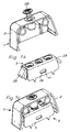
- the figures 2a to 2c show a fitting 31 which, with regard to its structure, is fitted with fitting 1 of FIGS. 2a to 2c basically coincides.
- the fitting 31 also serves to connect furniture panels, not shown, which abut one another at right angles.
- One furniture plate is assigned to a housing 32, the other furniture plate to a base 33.
- FIGS. 1a to 1c An essential difference to the fitting 1 of the FIGS. 1a to 1c results from the fitting 31 in FIGS. 2a to 2c with regard to the structural design of the base 33.
- the functional elements of the base 33, a holding profile 34 serving as a holding part and a latching part 35 which can be locked therewith can namely be displaced relative to one another in the latched position.
- This relative mobility of the holding profile 34 and the locking part 35 is achieved by appropriate dimensioning of locking openings 41 arranged in the leg surfaces of the holding profile 34 and of locking lugs 54 engaging in the locking openings 41.
- the latching openings 41 do not enclose the latching lugs 54 in the latching position of the holding profile 34 and latching part 35 in a form-fitting manner, but rather with play parallel to the surface of the furniture plate assigned to the base 33.
- elongated holes 55, 57 are provided in the web surface of the latching part 35 adjacent to a mounting hole 56.
- the web surface of the holding profile 34 has an elongated hole 44 between mounting bores 42, 43.
- the holding profile 34 is first pushed onto the locking part 35.
- the locking lugs 54 of the locking part 35 snap into the locking openings 41 of the holding profile 34 and are held in this position with play in the longitudinal direction of the locking openings 41.
- the base 33 is placed on the furniture panel assigned to it, aligned and screwed through the mounting holes 42, 43 of the holding profile 34 to the furniture panel.
- the fastening screws by means of which the base 33 is held on the relevant furniture panel, also penetrate the elongated holes 55, 57 of the latching part 35, but are not in engagement with the walls thereof.
- the latching part 35 can also be displaced relative to the holding profile 34 in the longitudinal direction of the latching openings 41 even after the base 33 has been screwed to the associated furniture panel.
- the housing 32 is screwed to the associated furniture plate via threaded sleeves 36, 37.
- the two fitting halves are firmly connected to the assigned furniture panels, they are attached to one another according to the mounting position.
- the housing 32 is pushed onto the base 33 and with it, as described above for the fitting 1 in FIGS. 1a to 1c described, locked.
- the base 33 is supported on the flanks of the inner wall of the housing 32 by means of locking arms 52, 53. Since the housing 32 covers the holding profile 34 in the mounting position with play and since the latching part 35 is held with play on the holding profile 34 by means of an elongated hole guide, there is mobility of the housing 32 relative to the holding profile 34 firmly connected to the relevant furniture panel the locking of the housing 32 with the base 33 furniture panels temporarily connected to each other can consequently be shifted against each other. In this way, the furniture panels can be arranged so that their edges are flush with each other.
- a fastening screw 58 is used, which is screwed into the mounting bore 56 of the locking part 35 by a threaded sleeve 38 on the housing 32.
- the fastening screw is tightened 58 effective fastening force in the longitudinal direction of the screw, the locking part 35 is pressed against the underside of the web surface of the holding profile 34 and held there by friction.
- the geometry of the elongated hole 44 allows the housing 32 to be displaced with the latching part 35 connected thereto via the fastening screw 58 relative to the holding profile 34 firmly connected to the associated furniture panel.
Landscapes
- Engineering & Computer Science (AREA)
- General Engineering & Computer Science (AREA)
- Mechanical Engineering (AREA)
- Furniture Connections (AREA)
- Connection Of Plates (AREA)
- Joining Of Building Structures In Genera (AREA)
Applications Claiming Priority (2)
| Application Number | Priority Date | Filing Date | Title |
|---|---|---|---|
| DE9316140U DE9316140U1 (de) | 1993-10-22 | 1993-10-22 | Beschlag zur Verbindung aneinanderstoßender Konstruktionselemente |
| DE9316140U | 1993-10-22 |
Publications (1)
| Publication Number | Publication Date |
|---|---|
| EP0653569A1 true EP0653569A1 (fr) | 1995-05-17 |
Family
ID=6899752
Family Applications (1)
| Application Number | Title | Priority Date | Filing Date |
|---|---|---|---|
| EP94115247A Withdrawn EP0653569A1 (fr) | 1993-10-22 | 1994-09-28 | Ferrure pour l'assemblage d'éléments de construction jointifs |
Country Status (2)
| Country | Link |
|---|---|
| EP (1) | EP0653569A1 (fr) |
| DE (1) | DE9316140U1 (fr) |
Cited By (1)
| Publication number | Priority date | Publication date | Assignee | Title |
|---|---|---|---|---|
| EP2020513A1 (fr) * | 2007-08-02 | 2009-02-04 | Hettich-Heinze GmbH & Co. KG | Ferrure destinée à relier deux plaques de meubles |
Citations (2)
| Publication number | Priority date | Publication date | Assignee | Title |
|---|---|---|---|---|
| FR1299833A (fr) * | 1961-07-25 | 1962-07-27 | Ferrure d'assemblage à blocage progressif par éléments coulissants pour meubles ou autres emplois | |
| DE9105568U1 (de) * | 1991-05-04 | 1991-06-13 | Häfele KG, 7270 Nagold | Beschlag, insbesondere für Möbelplatten |
-
1993
- 1993-10-22 DE DE9316140U patent/DE9316140U1/de not_active Expired - Lifetime
-
1994
- 1994-09-28 EP EP94115247A patent/EP0653569A1/fr not_active Withdrawn
Patent Citations (2)
| Publication number | Priority date | Publication date | Assignee | Title |
|---|---|---|---|---|
| FR1299833A (fr) * | 1961-07-25 | 1962-07-27 | Ferrure d'assemblage à blocage progressif par éléments coulissants pour meubles ou autres emplois | |
| DE9105568U1 (de) * | 1991-05-04 | 1991-06-13 | Häfele KG, 7270 Nagold | Beschlag, insbesondere für Möbelplatten |
Cited By (1)
| Publication number | Priority date | Publication date | Assignee | Title |
|---|---|---|---|---|
| EP2020513A1 (fr) * | 2007-08-02 | 2009-02-04 | Hettich-Heinze GmbH & Co. KG | Ferrure destinée à relier deux plaques de meubles |
Also Published As
| Publication number | Publication date |
|---|---|
| DE9316140U1 (de) | 1994-01-05 |
Similar Documents
| Publication | Publication Date | Title |
|---|---|---|
| DE69412563T2 (de) | Schrank mit Eckverbindung und ein Schaltschrank mit solchen Verbindungen | |
| EP0735283A2 (fr) | Dispositif de fixation | |
| DE3039499C2 (fr) | ||
| DE3912135C2 (fr) | ||
| DE3214528C2 (de) | Vorrichtung zur Festlegung von Instrumentengehäusen in einer Trägerplatte | |
| DE19837367C2 (de) | Rahmenprofil für einen Schaltschrank | |
| EP0127030A2 (fr) | Assemblage angulaire | |
| DE20015831U1 (de) | Teleskopierbarer Linearantrieb | |
| EP0067970B1 (fr) | Dispositif de fixation pour éléments de façade | |
| WO2015127924A1 (fr) | Armoire de commande | |
| CH652269A5 (en) | Quick mounting base made of plastic, for fixing an electrical device or printed-circuit board | |
| EP0653569A1 (fr) | Ferrure pour l'assemblage d'éléments de construction jointifs | |
| DE3500258A1 (de) | Gitterwerkdecke, insbesondere reinraumgitterwerkdecke | |
| DE102018102488A1 (de) | Anordnung zur Positionierung eines Flachteils an einem Schaltschrankrahmengestell sowie ein entsprechendes Verfahren | |
| DE4409155A1 (de) | Verbindungselement zur Verbindung von plattenförmigen Wandelementen | |
| EP4390042B1 (fr) | Ensemble constitué d'un vantail de porte en verre et d'un joint de porte automatique | |
| DE9303155U1 (de) | Duschkabine | |
| EP2586928B1 (fr) | Support de plaque en particulier pour panneaux en verre | |
| DE102005013086B4 (de) | System, bestehend aus einer Sockelblende und einer Abdeckung | |
| DE102004059419B4 (de) | Gerätegehäuse | |
| DE2749874C3 (de) | Nut-Feder-Verbindung für zusammensetzbare Wandelelemente | |
| DE3103291A1 (de) | An blend- und fluegelrahmen von fenstern, tueren od.dgl. ansetzbares verbindungselement | |
| DE2839974A1 (de) | Rahmenloser bildtraeger | |
| DE19833655C1 (de) | Befestigungselement | |
| EP1762691B1 (fr) | Dispositif d'étanchéité pour un coin de porte ou fenêtre |
Legal Events
| Date | Code | Title | Description |
|---|---|---|---|
| PUAI | Public reference made under article 153(3) epc to a published international application that has entered the european phase |
Free format text: ORIGINAL CODE: 0009012 |
|
| AK | Designated contracting states |
Kind code of ref document: A1 Designated state(s): AT BE CH DE DK ES FR GB GR IE IT LI LU MC NL PT SE |
|
| 17P | Request for examination filed |
Effective date: 19950331 |
|
| GRAG | Despatch of communication of intention to grant |
Free format text: ORIGINAL CODE: EPIDOS AGRA |
|
| 17Q | First examination report despatched |
Effective date: 19960507 |
|
| GRAH | Despatch of communication of intention to grant a patent |
Free format text: ORIGINAL CODE: EPIDOS IGRA |
|
| STAA | Information on the status of an ep patent application or granted ep patent |
Free format text: STATUS: THE APPLICATION IS DEEMED TO BE WITHDRAWN |
|
| 18D | Application deemed to be withdrawn |
Effective date: 19961009 |