EP0127030A2 - Assemblage angulaire - Google Patents
Assemblage angulaire Download PDFInfo
- Publication number
- EP0127030A2 EP0127030A2 EP84105296A EP84105296A EP0127030A2 EP 0127030 A2 EP0127030 A2 EP 0127030A2 EP 84105296 A EP84105296 A EP 84105296A EP 84105296 A EP84105296 A EP 84105296A EP 0127030 A2 EP0127030 A2 EP 0127030A2
- Authority
- EP
- European Patent Office
- Prior art keywords
- recess
- profile rail
- profile
- corner connector
- rail
- Prior art date
- Legal status (The legal status is an assumption and is not a legal conclusion. Google has not performed a legal analysis and makes no representation as to the accuracy of the status listed.)
- Granted
Links
Images

Classifications
-
- F—MECHANICAL ENGINEERING; LIGHTING; HEATING; WEAPONS; BLASTING
- F16—ENGINEERING ELEMENTS AND UNITS; GENERAL MEASURES FOR PRODUCING AND MAINTAINING EFFECTIVE FUNCTIONING OF MACHINES OR INSTALLATIONS; THERMAL INSULATION IN GENERAL
- F16B—DEVICES FOR FASTENING OR SECURING CONSTRUCTIONAL ELEMENTS OR MACHINE PARTS TOGETHER, e.g. NAILS, BOLTS, CIRCLIPS, CLAMPS, CLIPS OR WEDGES; JOINTS OR JOINTING
- F16B12/00—Jointing of furniture or the like, e.g. hidden from exterior
- F16B12/44—Leg joints; Corner joints
- F16B12/50—Metal corner connections
-
- Y—GENERAL TAGGING OF NEW TECHNOLOGICAL DEVELOPMENTS; GENERAL TAGGING OF CROSS-SECTIONAL TECHNOLOGIES SPANNING OVER SEVERAL SECTIONS OF THE IPC; TECHNICAL SUBJECTS COVERED BY FORMER USPC CROSS-REFERENCE ART COLLECTIONS [XRACs] AND DIGESTS
- Y10—TECHNICAL SUBJECTS COVERED BY FORMER USPC
- Y10T—TECHNICAL SUBJECTS COVERED BY FORMER US CLASSIFICATION
- Y10T403/00—Joints and connections
- Y10T403/46—Rod end to transverse side of member
- Y10T403/4602—Corner joint
-
- Y—GENERAL TAGGING OF NEW TECHNOLOGICAL DEVELOPMENTS; GENERAL TAGGING OF CROSS-SECTIONAL TECHNOLOGIES SPANNING OVER SEVERAL SECTIONS OF THE IPC; TECHNICAL SUBJECTS COVERED BY FORMER USPC CROSS-REFERENCE ART COLLECTIONS [XRACs] AND DIGESTS
- Y10—TECHNICAL SUBJECTS COVERED BY FORMER USPC
- Y10T—TECHNICAL SUBJECTS COVERED BY FORMER US CLASSIFICATION
- Y10T403/00—Joints and connections
- Y10T403/55—Member ends joined by inserted section
- Y10T403/555—Angle section
Definitions
- the invention relates to a device, in particular a mirror cabinet, with a first and a second profile rail, each of which has a hollow chamber, and with a corner connector, which is inserted into the hollow chamber of the first and second profile rail with a first and second pin .
- the pins of the corner connector have teeth on their outer surface. After being inserted into the hollow chambers of the profile rails, these toothings snap into the toothing provided there or into toothing to be inserted there.
- the profile rails are made of a thermoplastic material, which allows the production of the teeth mentioned.
- the manufacture of the teeth in the interior of the hollow chamber is nevertheless associated with a comparatively large production outlay, especially since suitable tools are introduced into the hollow chambers and the teeth are finally created by heating.
- there are limits especially since there are no special securing elements or additional fastening elements between the profiled rails and corner connector or its pin.
- Swiss patent specification 350 091 describes a corner connection of plate-shaped elements which have interlocking guide surfaces on their longitudinal edges. These guide surfaces are designed in the manner of a tongue and groove connection, the plate-shaped elements being connected to one another by means of further connecting elements, specifically in the form of fittings and head pins.
- Such a corner connection is hardly suitable for connecting profile rails with comparatively small end faces, especially since particular stability and dimensional stability can hardly be achieved. Furthermore, processing of the end faces of the profile rails to be connected, which would be comparable with the known corner connection, would require a not inconsiderable amount of work.
- the patent according to economic patent 58 800 of the German Democratic Republic describes a metal cupboard that can be produced in a plug-in construction, the side walls of which each have tabs in the form of feet on the underside. There is a base plate with slots into which the said feet of the side walls engage, a relative displacement of the side wall with respect to the base plate having to take place during assembly.
- a corner connector of the type mentioned at the beginning cannot readily be used in the known metal cabinet, especially since a corner connector cannot allow the required relative movement.
- German utility model 77 11 771 teaches a kit for shelves or the like, which contains a base plate with a multi-angled fitting part.
- An associated side wall also has a corresponding fitting part. The production and the connection of the mentioned fitting parts with the base plate or the side wall require a correspondingly large production and assembly effort.
- the invention is therefore based on the object of improving a device of the type mentioned at a low cost and production outlay in such a way that a high degree of stability and dimensional accuracy is ensured in the connection area of the profile rails.
- the device should have a long service life and be distinguished by a high level of functional reliability.
- the device should have high stability even with small dimensions of the profile rails and in particular with a small wall thickness and should be able to be assembled in a simple manner.
- the device is also intended to ensure a stable connection of the profiled rails which can be produced with little assembly effort. Finally, the device should be able to meet the operational requirements and conditions.
- the second profile rail have an extension which is inserted through an opening of the first profile rail and through an opening of the first pin. Furthermore, the first pin contains a first recess and the mentioned extension of the second profile rail has a second recess, a connecting element engaging through the two recesses.
- the device according to the invention is characterized by a simple and inexpensive construction and enables a dimensionally stable and exact connection thereof even with small dimensions of the profile rails. Since the approach is inserted into the openings of the corner connector and the first profile rail, there is a defined alignment and definition. Furthermore, the approach mentioned is by means of the verb tion element, in particular screw or grooved pin, firmly connected to the corner connector, so that overall a reliable and reliable connection is created.
- the device can be assembled with a comparatively small amount of assembly work, only the attachment of the second profile rail having to be passed through the two openings of the corner connector and the first profile rail and finally the final and firm connection only having to be made with the connecting element.
- the device can be assembled in the form of a frame from a total of four profile rails, which are connected at their ends in the manner according to the invention.
- mirror cabinets are mentioned as the preferred area of use, the device according to the invention can also be used in other areas of application, and it is only mentioned here by way of example of frames for shower partitions, windows or doors.
- the connecting element also engages in the two recesses of the pin and of the shoulder, as a result of which the corner connector and the second profile rail are mutually fixed. Furthermore, since the mentioned pin of the corner connector is inserted into the first profile rail and the said extension is passed through the opening of the first profile rail, a defined fixation of the first profile rail is also ensured.
- the corner connector is connected directly to the second profile rail by means of the connecting element. Since the approach of the second profile rail is also guided through the above-mentioned openings of the first profile rail and the corner connector, which in turn is inserted into the first profile rail, a stable and accurate connection of the two profile rails is ensured overall with little effort.
- the above-mentioned recesses of the pin and extension of the second profile rail run essentially in the direction of the longitudinal axis of the first profile rail.
- a reliable fixation can be achieved due to the parallelism of the recess, pin and first profile rail, without the corner connector itself being decisively weakened and its load-bearing capacity being adversely affected.
- it is of crucial importance that, by simply inserting an attachment of the one profile rail into said and aligned openings of the corner connector and other profile rail, an exact and dimensionally accurate alignment is achieved and a permanent and functional connection is created on the basis of the screw or the like .
- the profile rails themselves do not require any screw channels extending over their entire length, since the connecting element is connected to the corner connector according to the invention.
- the geometric axis of the recess in the mentioned approach to the geometric axis of the recess in the corner connector has a predetermined distance from an end edge of the second profile rail, said end edge on an inner surface of the first profile rail or of the corner connector.
- the distance mentioned is in the range between 0.1 and 1.0 mm.
- the connecting element can be inserted into the said recesses from the outside of the profile rails.
- the second profile rail has on its outside, at least in the region of the attachment, an edge set back with respect to the same.
- the recesses are thus directly accessible from the outside, and the connecting element can be inserted directly into the easily accessible recesses and anchored or screwed or otherwise fastened there. This is of particular importance in view of the limited space available in comparatively small mirror cabinets, in which screws or the like previously had to be fastened from the inside.
- the approach and / or the recess of the second profile rail and / or the opening of the first profile rail are produced by punching out in a preferred embodiment.
- the profiled rails cut to the required length only have to be subjected to a punching process which can be carried out in a short amount of time.
- the end faces and / or the inner webs of the profiled rails have a predetermined distance from the outer webs of the respective other profiled rails.
- the inner webs each end inside the other profile rail.
- a special processing of the end faces, in particular after punching out, is not necessary.
- the outer webs are visible from the outside of the device, while the end faces of the inner webs mentioned are hidden.
- a facing element is arranged in the corner area between the outer webs. With this facing element, the edges of the outer webs are covered, so that overall there is a harmonious and self-contained device.
- the facing element also covers the connection element located according to the invention behind the outer webs or inside the profile rail.
- the facing element For a reliable connection of the facing element, it is either fastened in the corner area by means of a screw or the like or else clipped on via a snap connection.
- the snap connection which is preferably provided and which has latching elements or the like which engage behind, enables quick and easy installation.
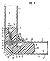
- first profile rail 1 and a second profile rail 2 of the device which are arranged at right angles to one another.
- the rails 1 and 2 each have an inner web 4, 6 and an outer web 8, 10. Between the webs mentioned are hollow chambers 11, 12, in which right-angled pins 14, 16 of a corner connector 18 are inserted.
- the second profile rail 2 has a projection 20 which extends through an opening 22 of the inner web 4 of the profile rail 1. Furthermore, the projection 20 is passed through an aligned opening 24 of the pin 14 from the corner connector 18.
- the first pin 14 of the corner connector 18 has a first recess 28.
- the extension 20 has in the region of the hollow chamber 11 of the profile rail 1 a second recess 26 which is substantially flush with the recess 28 of the said pin 14.
- the geometric axis 27 of the second recess 26 is arranged at a predetermined distance 25 from the geometric axis 29 of the first recess 28 in the corner connector 18, specifically in the direction of the inner surface 31 of the first profile rail.
- a connecting element 30, here in the form of a screw, is introduced into the said recesses 26, 28.
- the end face 32 of the extension 20 and also the end face 34 of the inner web 4 of the first profile rail 1 are each at a predetermined distance with respect to the outer webs 8 and 10.
- the end face 34 protrudes into a recess 36 of the corner connector 18.
- a facing element 42 is provided on the outside 40, which partially abuts the end edges 44, 46 of the two outer webs 8, 10.
- the corner connector 18 with its pin 14 is first inserted into the hollow chamber 11 of the profile rail 1.
- the end face 34 lies on the bottom face 48 of the corner connector 18, as a result of which a defined alignment is achieved.
- the inner web 6 of the second profile rail lies directly on the surface 49 of the pin 16 or it is guided in the opening 24 of the corner connector 18.
- the opening 22 and the lower end 51 of the inner web 4 of the first profile rail are designed accordingly, so that tension can also be achieved in this respect.
- the second profile rail 2 is added in such a way that the projection 20 is pushed through the aligned openings 22, 24.
- the connecting element 30 is inserted from the outside 40 into the aligned recesses 26, 28 in the pin 14 of the corner connector 18.
- the connecting element 30 is designed here as a screw which is screwed into the recess 28 in a simple manner, with a rotation lock subsequently being achieved by means of a spring ring 50.
- the corner connector 18 has, in the outer corner area, a longitudinal groove 52 extending perpendicular to the plane of the drawing, in which the head of the connecting element 30 and also the facing element 42 are located. This longitudinal groove 52, like the edges 44 and 46, is covered by means of the facing element 42.
- the facing element can be screwed on by means of a screw. Alternatively, a snap connection can also be provided in order to clip in the facing element 42 in the corner region.
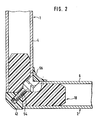
- FIG. 2 shows the device in another sectional plane, the veneer element 42 now being screwed onto the corner connector 18 by means of a screw 54.
- the above-mentioned recess 36 has been expanded somewhat so that the screw 54 can be screwed in from the inside.
- the profile rails 1, 2 and their inner webs 4, 6 are also shortened in the manner shown in the area of this screw 54.
- an internally rounded cover strip 56 which, according to the invention, extends over the entire depth of the profile rails, i.a. the opening for the screw 54 between the inner webs 4, 6 is also covered.
- FIG 3 shows the first profile rail 1 with two openings 22.
- the corner connector 18 also has two openings 24.
- the position of the cuts according to FIGS. 1 and 2 is indicated by the section line I or II.
- the profile rail 2 also has two lugs 20, by means of which, in cooperation with the corner connector 18, the connection to the profile rail 1 already explained in detail above is achieved.
- the corner connector 18 extends practically over the entire width of the two rails 1 and 2. Since the corner connector 18 engages with its pegs in the hollow chambers of the profile rails 1 and 2 over a width which is large according to the invention, a defined alignment of the two profile rails 1 and 2 is ensured.
- the second profile rail 2 lies with its end edge 58 in the assembled state on the inner surface 31 of the first profile rail. Due to the above-described offset of the geometric axes of the recess 26 and the recess in the corner connector 18, the end edge 58 is pressed against the inner surface 31.
- the distance mentioned is approximately in the range between 0.1 and 1.0 mm, so that the manufacturing-related tolerances etc. can be compensated for without difficulty in order to obtain a play-free connection.
- the end edge 58 could also lie directly against the inner surface 60 of the corner connector 18 in a variant which is not shown here, the aforementioned distance of the recess likewise being present. It can be seen that here too a bracing of the corner connector and profile rail 2 is achieved.
Landscapes
- Engineering & Computer Science (AREA)
- General Engineering & Computer Science (AREA)
- Mechanical Engineering (AREA)
- Mutual Connection Of Rods And Tubes (AREA)
- Furniture Connections (AREA)
- Mirrors, Picture Frames, Photograph Stands, And Related Fastening Devices (AREA)
- Joining Of Building Structures In Genera (AREA)
- Assembled Shelves (AREA)
- Joining Of Corner Units Of Frames Or Wings (AREA)
- Connection Of Plates (AREA)
Priority Applications (1)
| Application Number | Priority Date | Filing Date | Title |
|---|---|---|---|
| AT84105296T ATE28923T1 (de) | 1983-05-30 | 1984-05-10 | Eckverbindung. |
Applications Claiming Priority (2)
| Application Number | Priority Date | Filing Date | Title |
|---|---|---|---|
| DE3319627A DE3319627C2 (de) | 1983-05-30 | 1983-05-30 | Eckverbindung |
| DE3319627 | 1983-05-30 |
Publications (3)
| Publication Number | Publication Date |
|---|---|
| EP0127030A2 true EP0127030A2 (fr) | 1984-12-05 |
| EP0127030A3 EP0127030A3 (en) | 1985-07-10 |
| EP0127030B1 EP0127030B1 (fr) | 1987-08-12 |
Family
ID=6200271
Family Applications (1)
| Application Number | Title | Priority Date | Filing Date |
|---|---|---|---|
| EP84105296A Expired EP0127030B1 (fr) | 1983-05-30 | 1984-05-10 | Assemblage angulaire |
Country Status (5)
| Country | Link |
|---|---|
| US (1) | US4527364A (fr) |
| EP (1) | EP0127030B1 (fr) |
| AT (1) | ATE28923T1 (fr) |
| CA (1) | CA1209635A (fr) |
| DE (2) | DE3319627C2 (fr) |
Cited By (1)
| Publication number | Priority date | Publication date | Assignee | Title |
|---|---|---|---|---|
| WO2007006453A1 (fr) | 2005-07-07 | 2007-01-18 | Gm Global Technology Operations, Inc. | Procede pour calculer la depression dans le servofrein d'un vehicule a moteur a allumage commande |
Families Citing this family (12)
| Publication number | Priority date | Publication date | Assignee | Title |
|---|---|---|---|---|
| US4799529A (en) * | 1986-11-06 | 1989-01-24 | Charmac, Inc. | Wardrobe door |
| DE3801772A1 (de) * | 1988-01-22 | 1989-08-03 | Leidse Houthandel | Verbindungsanordnung |
| US4886326A (en) * | 1988-01-29 | 1989-12-12 | Tetrad Marketing/Sales Ltd. | Interlock system for ready to assemble furniture, and furniture incorporating such system |
| DE3805422C1 (fr) * | 1988-02-22 | 1988-12-15 | Rittal-Werk Rudolf Loh Gmbh & Co Kg, 6348 Herborn, De | |
| DE3809487C1 (en) * | 1988-03-22 | 1989-04-20 | Heinz Georg Huenibach Thun Ch Baus | Cabinet |
| US5319906A (en) * | 1992-05-06 | 1994-06-14 | Michael Hayden | Stage platform assembly and method of making same |
| US5687533A (en) * | 1995-06-15 | 1997-11-18 | Andersen Corporation | Method and apparatus for connecting window frame segments |
| US6881005B2 (en) * | 2001-11-09 | 2005-04-19 | Saul Siney Sosa | Frame connection mechanism |
| US6782672B2 (en) * | 2002-10-08 | 2004-08-31 | Alliance Spacesystems, Inc. | Sandwich panel structural joint |
| GB201721620D0 (en) * | 2017-12-21 | 2018-02-07 | Matki Plc | Mitred cornered frame clamp |
| GB2573811B (en) * | 2018-05-18 | 2020-12-30 | Trieste Group One Ltd | Modular Frame |
| US20200149288A1 (en) | 2018-11-13 | 2020-05-14 | Katerra Inc. | Floor panel |
Family Cites Families (20)
| Publication number | Priority date | Publication date | Assignee | Title |
|---|---|---|---|---|
| DD58800A (fr) * | ||||
| DE7437173U (de) * | 1975-02-27 | Dreyer H | Schrank od. dgl. kastenförmiges Möbel | |
| US2604342A (en) * | 1944-12-12 | 1952-07-22 | John L Holmes | Prefabricated structural assembly |
| US2764314A (en) * | 1952-07-16 | 1956-09-25 | Skydyne Inc | Corner construction for a receptacle |
| NL211695A (fr) * | 1955-10-26 | 1900-01-01 | Fils Jacques Huguenin | |
| BE552381A (fr) * | 1955-11-07 | 1900-01-01 | ||
| DE1196429B (de) * | 1958-04-19 | 1965-07-08 | Ulrich Grajecki Dipl Ing | Eckverbindung fuer Hohlprofile |
| DE1218677B (de) * | 1960-08-24 | 1966-06-08 | Fortschritt Buero Einrichtungs | Aus Metallrohren bestehendes Fussgestell fuer Moebel, insbesondere Bueromoebel |
| DE1225833B (de) * | 1963-03-26 | 1966-09-29 | Greimbau Lizenz Gmbh | Zerlegbarer Holztragrost |
| US3574378A (en) * | 1969-05-26 | 1971-04-13 | James H Heywood | Strengthening insert and fastener for tubular constructions |
| AT307656B (de) * | 1970-12-14 | 1973-06-12 | Duepree Hans Werner | Systembauteil |
| DE2129858A1 (de) * | 1971-06-16 | 1972-12-21 | Metallbau Bedarf Gmbh | Rahmen von Fenstern und Tueren aus Hohlprofilen,dessen Ecken durch eingebaute Winkelstuecke verstaerkt sind |
| DE7522584U (de) * | 1974-07-23 | 1976-02-12 | Reynolds Aluminium Europe, En Abrege Aleurope S.A., Ghlin (Belgien) | Bauelementensatz für die Montage von Metallstrukturen mit Verbindungsanordnung |
| GB1488083A (en) * | 1975-01-14 | 1977-10-05 | Nexus Mfg Ltd | Mechanical connections between adjacent members |
| FR2299834A1 (fr) * | 1975-02-06 | 1976-09-03 | Guillemin Henri | Rayonnage |
| SE398140B (sv) * | 1976-02-19 | 1977-12-05 | T W Weibull | Forbindningsanordning |
| DE2738321A1 (de) * | 1976-09-09 | 1978-03-16 | Franco De Faccio | Verbindungskupplung fuer rohrteile |
| DE7711771U1 (de) * | 1977-04-15 | 1977-09-01 | Fritz Schaefer Gmbh, Fabriken Fuer Lager- Und Betriebseinrichtungen, Salchendorf Bei Neunkirchen, Kreis Siegen, 5908 Neunkirchen | Bausatz fuer regale o.dgl. |
| FR2432638A1 (fr) * | 1978-08-03 | 1980-02-29 | Simonian Richard | Armature metallique en tubes de section carree |
| DE8202245U1 (de) * | 1982-01-29 | 1982-05-13 | Reisbeck, Günter, 7270 Nagold | Rahmenkonstruktion, insbesondere fuer moebel |
-
1983
- 1983-05-30 DE DE3319627A patent/DE3319627C2/de not_active Expired
-
1984
- 1984-05-10 EP EP84105296A patent/EP0127030B1/fr not_active Expired
- 1984-05-10 DE DE8484105296T patent/DE3465369D1/de not_active Expired
- 1984-05-10 AT AT84105296T patent/ATE28923T1/de not_active IP Right Cessation
- 1984-05-22 US US06/613,072 patent/US4527364A/en not_active Expired - Fee Related
- 1984-05-23 CA CA000454911A patent/CA1209635A/fr not_active Expired
Cited By (1)
| Publication number | Priority date | Publication date | Assignee | Title |
|---|---|---|---|---|
| WO2007006453A1 (fr) | 2005-07-07 | 2007-01-18 | Gm Global Technology Operations, Inc. | Procede pour calculer la depression dans le servofrein d'un vehicule a moteur a allumage commande |
Also Published As
| Publication number | Publication date |
|---|---|
| ATE28923T1 (de) | 1987-08-15 |
| US4527364A (en) | 1985-07-09 |
| EP0127030A3 (en) | 1985-07-10 |
| DE3319627A1 (de) | 1984-12-06 |
| DE3319627C2 (de) | 1985-08-14 |
| DE3465369D1 (en) | 1987-09-17 |
| CA1209635A (fr) | 1986-08-12 |
| EP0127030B1 (fr) | 1987-08-12 |
Similar Documents
| Publication | Publication Date | Title |
|---|---|---|
| EP0136431B1 (fr) | Ossature en profilés | |
| EP0098435B1 (fr) | Elément de construction | |
| EP0127030A2 (fr) | Assemblage angulaire | |
| EP4230881B1 (fr) | Elément de liaison | |
| DE20100747U1 (de) | Riegel/Pfosten-Konstruktion | |
| EP2754805A2 (fr) | Tringle de verrouillage pour une crémone | |
| DE2126955A1 (de) | Beschlag zum Zusammenfügen von zwei und mehr aufeinander senkrecht stehenden Wänden, insbesondere von plattenförmigen Möbelwänden | |
| DE2745896A1 (de) | Moebelbeschlag zum verstellen einer schubkastenblende | |
| EP0104340A2 (fr) | Agencement, en particulier pour une cloison de douche | |
| EP0267200B1 (fr) | Dispositif pour l'assemblage demontable de deux elements de construction | |
| EP0111185B1 (fr) | Cadre, en particulier pour une cloison de douche | |
| AT403500B (de) | Beschlagteileverbindung | |
| DE2344971A1 (de) | Treibstangenbeschlag fuer fenster, tueren od. dgl. | |
| EP2754803A2 (fr) | Crémone de fenêtre ou de porte | |
| DE2744052A1 (de) | Beschlag fuer tueren und waende aus glas | |
| DE102004043964A1 (de) | Verbindungsvorrichtung | |
| DE3145375C2 (de) | Mehrteiliges Rahmenprofil | |
| DE8814754U1 (de) | Fenster oder Tür mit vorzugsweise aus Hohlprofilen bestehenden Holmen | |
| DE8322475U1 (de) | Gestell aus Profilstäben | |
| EP4575119B1 (fr) | Raccord en t et procédé d'assemblage d'un raccord en t | |
| EP1186723A2 (fr) | Dispositif de fixation pour une façade avec montants et traverses | |
| DE9308713U1 (de) | Eck- oder Sprossenverbindung von Rahmenprofilen | |
| DE4444413A1 (de) | Bausatz für Skelettkonstrukionen wie Regale, Rahmen, Ständer u. dgl. | |
| EP2020513B1 (fr) | Ferrure destinée à relier deux plaques de meubles | |
| DE3613655C1 (de) | In Moebel,Waende od.dgl. einsetzbare Rastschiene und Verfahren zum Einsetzen einer solchen Rastschiene |
Legal Events
| Date | Code | Title | Description |
|---|---|---|---|
| PUAI | Public reference made under article 153(3) epc to a published international application that has entered the european phase |
Free format text: ORIGINAL CODE: 0009012 |
|
| 17P | Request for examination filed |
Effective date: 19840510 |
|
| AK | Designated contracting states |
Designated state(s): AT CH DE GB IT LI |
|
| PUAL | Search report despatched |
Free format text: ORIGINAL CODE: 0009013 |
|
| AK | Designated contracting states |
Designated state(s): AT CH DE GB IT LI |
|
| 17Q | First examination report despatched |
Effective date: 19860806 |
|
| GRAA | (expected) grant |
Free format text: ORIGINAL CODE: 0009210 |
|
| AK | Designated contracting states |
Kind code of ref document: B1 Designated state(s): AT CH DE GB IT LI |
|
| REF | Corresponds to: |
Ref document number: 28923 Country of ref document: AT Date of ref document: 19870815 Kind code of ref document: T |
|
| REF | Corresponds to: |
Ref document number: 3465369 Country of ref document: DE Date of ref document: 19870917 |
|
| ITF | It: translation for a ep patent filed | ||
| PLBE | No opposition filed within time limit |
Free format text: ORIGINAL CODE: 0009261 |
|
| STAA | Information on the status of an ep patent application or granted ep patent |
Free format text: STATUS: NO OPPOSITION FILED WITHIN TIME LIMIT |
|
| 26N | No opposition filed | ||
| REG | Reference to a national code |
Ref country code: CH Ref legal event code: PUE Owner name: B.V. LEIDSE HOUTHANDEL VORHEEN KATER EN WIETHOFF |
|
| ITTA | It: last paid annual fee | ||
| ITPR | It: changes in ownership of a european patent |
Owner name: CESSIONE;ALTURA LEIDEN HOLDING B.V. |
|
| PGFP | Annual fee paid to national office [announced via postgrant information from national office to epo] |
Ref country code: DE Payment date: 19900724 Year of fee payment: 7 |
|
| REG | Reference to a national code |
Ref country code: CH Ref legal event code: PFA Free format text: ALTURA LEIDEN HOLDING B.V. |
|
| PGFP | Annual fee paid to national office [announced via postgrant information from national office to epo] |
Ref country code: GB Payment date: 19910425 Year of fee payment: 8 |
|
| PGFP | Annual fee paid to national office [announced via postgrant information from national office to epo] |
Ref country code: AT Payment date: 19910527 Year of fee payment: 8 |
|
| PGFP | Annual fee paid to national office [announced via postgrant information from national office to epo] |
Ref country code: CH Payment date: 19910617 Year of fee payment: 8 |
|
| PG25 | Lapsed in a contracting state [announced via postgrant information from national office to epo] |
Ref country code: DE Effective date: 19920303 |
|
| PG25 | Lapsed in a contracting state [announced via postgrant information from national office to epo] |
Ref country code: GB Effective date: 19920510 Ref country code: AT Effective date: 19920510 |
|
| PG25 | Lapsed in a contracting state [announced via postgrant information from national office to epo] |
Ref country code: LI Effective date: 19920531 Ref country code: CH Effective date: 19920531 |
|
| GBPC | Gb: european patent ceased through non-payment of renewal fee |
Effective date: 19920510 |
|
| REG | Reference to a national code |
Ref country code: CH Ref legal event code: PL |