EP0653739B1 - Modulares Anzeigesystem - Google Patents
Modulares Anzeigesystem Download PDFInfo
- Publication number
- EP0653739B1 EP0653739B1 EP94307613A EP94307613A EP0653739B1 EP 0653739 B1 EP0653739 B1 EP 0653739B1 EP 94307613 A EP94307613 A EP 94307613A EP 94307613 A EP94307613 A EP 94307613A EP 0653739 B1 EP0653739 B1 EP 0653739B1
- Authority
- EP
- European Patent Office
- Prior art keywords
- module
- walls
- base
- modules
- recited
- Prior art date
- Legal status (The legal status is an assumption and is not a legal conclusion. Google has not performed a legal analysis and makes no representation as to the accuracy of the status listed.)
- Expired - Lifetime
Links
- 230000005611 electricity Effects 0.000 claims description 6
- 239000004020 conductor Substances 0.000 claims description 3
- 230000000007 visual effect Effects 0.000 claims description 2
- 230000007246 mechanism Effects 0.000 description 7
- 230000000712 assembly Effects 0.000 description 6
- 238000000429 assembly Methods 0.000 description 6
- 239000004033 plastic Substances 0.000 description 4
- 235000013305 food Nutrition 0.000 description 3
- 235000013410 fast food Nutrition 0.000 description 2
- 238000003491 array Methods 0.000 description 1
- 230000009286 beneficial effect Effects 0.000 description 1
- 235000013361 beverage Nutrition 0.000 description 1
- 235000011850 desserts Nutrition 0.000 description 1
- 238000004519 manufacturing process Methods 0.000 description 1
- 239000011159 matrix material Substances 0.000 description 1
- 239000002184 metal Substances 0.000 description 1
- 230000035939 shock Effects 0.000 description 1
- 239000002023 wood Substances 0.000 description 1
Images


Classifications
-
- G—PHYSICS
- G09—EDUCATION; CRYPTOGRAPHY; DISPLAY; ADVERTISING; SEALS
- G09F—DISPLAYING; ADVERTISING; SIGNS; LABELS OR NAME-PLATES; SEALS
- G09F13/00—Illuminated signs; Luminous advertising
- G09F13/04—Signs, boards or panels, illuminated from behind the insignia
-
- G—PHYSICS
- G09—EDUCATION; CRYPTOGRAPHY; DISPLAY; ADVERTISING; SEALS
- G09F—DISPLAYING; ADVERTISING; SIGNS; LABELS OR NAME-PLATES; SEALS
- G09F13/00—Illuminated signs; Luminous advertising
- G09F13/04—Signs, boards or panels, illuminated from behind the insignia
- G09F13/0418—Constructional details
- G09F13/0454—Slidable panels or parts
Definitions
- the present invention relates to back lighted display signs, and more particularly to such signs which are formed by modules that can be combined side-by-side to form a wide variety of different sized and shaped sign assemblies.
- these signs consist of a number of panels with each panel displaying a different category of items. For example, one panel may list hot sandwiches, with another panel for cold sandwiches, and yet another panel listing beverages and desserts. A panel may also display a photographic reproduction of a food item being offered for sale as a way in which to create customer interest. Quite often these signs are back lit with the lettering and photographic image being translucent to emit light.
- each module contains its own lamp assembly, a mechanism for supplying electrical current to each module has to be provided. It is undesirable to have a separate external cord for each module as the number of such cords because of the numerous cords that would extend from a large sign assembly. It is also desirable to provide a mechanism by which a trim frame can be attached around the perimeter of the assembled sign in order to create a decorative appearance to the overall sign and set it apart from its surroundings.
- US-A-3934365 describes a modular sign assembly in which two modules each having a plurality of walls, are abutted wall-to-wall and each contain a light bulb for illuminating a respective display panel.
- a general object of the present invention is to provide a modular sign system in which a plurality of modules can be interconnected in one or two dimensional arrays to form a sign assembly.
- each module has a base that includes a plurality of walls attached to and extending from a base panel. Each wall has at least one dovetail groove in an exterior surface.
- a lamp tray containing at least one light bulb is located within the walls of the base.
- a bezel extends over the lamp tray and abuts the base walls. The bezel also has walls which have dovetail grooves, each of which aligns with a similar dovetail groove in the base.
- a separate dovetail union is positioned in each dovetail groove in the base and extends into the associated dovetail groove in the bezel.
- double dovetail unions are inserted into the grooves in the abutting walls of the two modules to secure the modules together.
- Single dovetail unions are used to fill in the dovetail grooves on exposed walls of a module.
- Another type of dovetail union has a mechanism for fastening an optional decorative frame around the perimeter of one or more assembled modules.
- the preferred version of the module has a wiring assembly with electrical connectors located at each corner of the module.
- cables couple the corner connectors of adjacent modules. This interconnection of the modules enables an external electrical power connection to be made to only one module in the assembly with the other modules receiving power from that one module.
- Another feature of the present modular sign concept is a mechanism by which components of two rectangular modules can be combined to form a square module or a larger rectangular module.
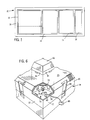
- a sign assembly 10 such as is used to display a menu in a fast food restaurant, comprises a member of modules 12, 14, 16, and 18 abutting one another.
- Each module 12-18 has a self contained display area surrounded by a border.
- the modules are fabricated in two sizes with one size used as modules 14 and 16, and module 18 being one half the size of module 14.
- the height of the both sized modules is the same and preferably three times the width of the smaller module 18.
- the width of module 18 is 22.86 cm (nine inches)
- the width of module 16 is 45.72 cm (eighteen inches)
- their individual heights are 68.58 cm (twenty-seven inches).
- This dimensional relationship 9-18-27 allows the two different size modules to be combined in different numbers and horizontal and vertical orientations to form a wide variety of sized and shaped sign assemblies.
- a greater single display area can be formed by combining sections from two modules. Because the widths of the two different sized rectangular modules equals their height, square module 12 is formed using parts of those different modules. For example, parts of a larger size module form the upper section (above the dashed line) in module 12 with the lower portion uses parts of a smaller module. The unique manner in which these two module sections are joined enables a single large square display to be created and appear to be a third size of module. Carrying this concept further, components of two large rectangular modules can be joined to form a much larger rectangular module, and components of more than two modules can be joined to create an even larger single display module.
- modules can form a sign assembly by merely abutting them side-by-side, a more attractive assembly is formed by placing a decorative frame 19 around the perimeter of the assembly.
- the frames are created from standardized linear components having different lengths.
- a variety of wood, plastic and metal linear segments can be provided to further individualize a given sign assembly.
- FIG. 2 illustrates the components of module 14 and the mechanism by which that module is connected to module 16.
- Module 14 includes a base 20 formed by a flat rectangular rear panel 25 from which extend four walls 21, 22, 23 and 24 to form a box-like base with an open front.
- the base 20 has a rectangular shape with the ratio of the width formed by walls 20 and 23 to the length formed by walls 22 and 24 being two to three.
- a number of dovetail grooves 26 are formed at regular intervals along the outer surface of each base wall 21-24. Dovetail grooves are well known in the art and the width of the groove widens going into the wall from the outer surface as shown in greater detail in Figure 6.
- the second module 16 has a similar base 30 with walls 31, 32 and 33.
- the walls of the base 30 also have dovetail grooves 26 in their outer surfaces and spaced at the same intervals as in base 20.
- each double dovetail union 34 has an inwardly extending V shape which conforms to the tapered walls of the dovetail grooves 26.
- Figures 3A and 3B illustrate the details of the double dovetail union 34.
- a separate flexible finger 40 and 42 Centered along a short edge of the dovetail union on both major surfaces 36 and 38 is a separate flexible finger 40 and 42, respectively.
- the double dovetail union is made out of a plastic which allows the finger to flex with respect to the main body of the union 34.
- a rib 44 and 46 Approximately midway along the length of each of the fingers 40 and 42 is a rib 44 and 46, respectively.
- the double dovetail union 34 is slid into the aligned pair of dovetail grooves 26 from the rear of bases 20 and 30.
- the user pinches the two fingers 40 and 42 together to retract the ribs 44 and 46 inwardly with respect to the major surfaces 36 and 38.
- This allows the union 34 to slide through the aligned dovetail grooves 26 in the bases 20 and 30 until the ribs 44 and 46 align with a detent 48 in each groove.
- fingers 40 and 42 are released so that the ribs 44 and 46 enter the detents 48.
- the engagement of the ribs with the detents holds the double dovetail union 34 in place, preventing further sliding along the grooves 26.
- wall 21 may be exposed to view in the modular sign assembly 10.
- the open dovetail grooves 26 in that wall are filled by a single dovetail union 50 to create a relatively smooth edge surface for the module 14.
- Single dovetail union 50 shown in detail in Figures 4A and 4B, is sized to be held in the dovetail groove 26 by friction.
- the modular sign assembly 10 may have a decorative frame 19 around its perimeter.
- a trim dovetail union 56 are used in place of connect unions 50 to connect the decorative frame to the exposed edges of each base 20 and 30.
- the trim dovetail union 56 is similar to the single dovetail union 50 with the addition of a post 60 on the exposed major surface.
- the post 60 has a circular cylindrical shaft 60 extending from the major surface of the union 56.
- a disk-shaped head 64 is at the remote end of the shaft 62 and a ring 66 is located midway along the shaft 62 between major surface 57 and the head 64.
- This combination forms a first space in between surface 57 and ring 66 and a second space between ring 66 and head 64.
- a section of the decorative frame 19 has a notch 68 that is adapted to slide into one of the spaces on post 60 and snap over the shaft 62.
- the post acts as a fastener holding the frame section 58 in place along the edge of the base 30. Only a short section of the entire decorative frame 19 is shown and the trim dovetail unions 56 would also be used to attached the frame 19 to base 20 of module 14.
- a box-like connector housing 72 is formed in each corner of the two bases 20 and 30.
- the sign assembly 10 is supplied with electricity by a cord 69 that extends through a hole 71 in the connector housing 72 at one corner of the base.
- Each connector housing 72 has a hole and the manufacture selects one of them through which to run the cord 69.
- the remote end of cord 69 has a plug 67 for a conventional electrical outlet.
- portions of walls 21 and 22 and base panel 25 at the rear corners of the base 20 are removed to form externally opening cavities 73 of the connector housing 72.
- An electrical connector 74 is in each cavity 73 attached to a wall of the respective connector housing 72.
- Pairs of wires 76 extend between the lamp tray connector 70 and the connectors 74 in each housing 72.
- the combination of the connectors 70 and 74 and wires 76 form an electrical cable assembly for conducting electricity throughout the base.
- the second base 30 has a similar cable assembly which does not have an externally extending power cord 69 connected to it. Instead, the second sign module 16 receives electrical power from the first module 14.
- a cable 78 extends from a connector 74 in one corner of the first base 20 to a similar connector in a connector housing 72 at a corner of the second base 30.
- This cable 78 is shown in greater detail in Figure 6 and has a pair of electrical conductors with plugs 80 at each end. The plugs 80 are inserted into the connector 74 in each of the bases 20 and 30 to convey electricity therebetween.
- An exterior corner cover 82 closes the cavity 73 providing a finished corner to the base 20. Notches 84 are provided in the edge of the cover 82 for the cable 78.
- the electrical cable assembly in each bases 20 and 30 enables only one module (e.g. 14) of the sign assembly 10 to be externally supplied with electricity.
- the remaining modules 12, 16 and 18 receive power from the module 14, either directly or in a daisy chain manner.
- the module which receives power from the external source may be placed at any location in the sign assembly because the corner connectors allow the base cable assemblies to be interconnected electrically regardless of the physical configuration of the sign assembly.
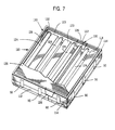
- a lamp tray 90 contains a plurality of standard fluorescent light bulbs 92. Sockets 93 are provided in the light tray 90 to receive the end terminals of each light bulb 92 and a wiring harness and ballast transformers (not shown) are located on the underside of the light tray 90.
- the underside of the light tray 90 also has an electrical connector 91 which mates connector 70 on the rear panel 25 of the base 20 when the tray is placed into the base 20 between the walls 21-24.
- the lamp tray 90 is fastened onto the base 20 by a plurality of machine screws (not shown).
- the lamp tray 90 may be removed from the base 20. When this occurs, the electricity is disconnected from the lamp tray, thereby preventing accidental shock to the worker servicing the electrical components of the lamp tray 90.
- a rectangular bezel 94 has four walls 95, 96, 97 and 98 interconnected to form a central opening 100.
- the bezel is placed over the lamp tray 90 onto the exposed edges of the base walls 21-24. Closed dovetail grooves 99 are formed in the bezel walls 95-98 and receive the exposed ends of the dovetail unions 34 and 50 projecting from the base 20. In addition to the unions 34 and 50 holding the bezel in place on base 20, machine screws are used to fasten the components.
- the bezel 94 holds a display panel 102 that contains the visual message for the sign.
- a sign module 14 for a restaurant can have a photographic image of a food item, or a listing of the menu items and their respective prices.
- the display panel 102 is back lighted by the light bulbs 92 and a menu display is formed by translucent characters surrounded by an opaque matrix.
- One type of a display panel 102 comprises a transparent sign board 103 to which are fastened a plurality of parallel retainers 104 between which the user inserts strips with the lettering for each line of the sign.
- a hinge 107 is attached along one edge of the sign board 103 and also attaches to a cover 105 which consists of a frame holding a transparent sheet of plastic.
- the sign board 103 slides into notches in opening 100 of the bezel 94 which hold the display panel in place when the module 14 is mounted vertically. By sliding the display panel 102 upward and pulling it out, it can be removed from the bezel 98 without unfastening the bezel from the other components of the sign module 14.
- the pin of hinge 107 rests within a notch 106 in the bezel allowing the cover 105 to be opened away from the sign board 103 when the display panel 102 is held in bezel 94. This action permits the user to gain access to the lettering strips in order to change the message.
- the entire display board 102 also can be removed from the bezel 94 to edit the message.
- a flat plastic panel containing a permanent message or photographic image can be inserted into the bezel 94 in place of the hinged display panel 102. It will be apparent to one skilled in the art that other forms of panels can be place into the bezel 94 to form different types of displays.
- a similar combination of a light tray, bezel and display panel are mounted on the base 30 for the second sign module 16, although those components have not been illustrated in Figure 2.
- modules 14, 16 and 18 are rectangular having a height which is greater than their width.
- the height of the modules 16 and 18 are the same.
- the width of module 16 is twice that of module 18 and their combined widths equal their individual heights. This dimensional relationship enables square module 12 to be formed by joining segments of the two different sized rectangular modules.
- a base 112 similar to base 20 in Figure 2, for a larger rectangular module, is placed against a base 114 for the smaller rectangular module. Because the width of the larger module is two-thirds its height and the width of the smaller module is one-thirds its height the combined width of the joined modules equals their height forming a square unit 110.
- the two bases may be held together by double dovetail unions 34 which are not visible in the illustration of the assembled unit.
- Conventional single dovetail unions 50 are shown positioned in each of the outer dovetail grooves in decorative frame is to be placed around the square unit 110 trim dovetail unions 56 are used in place of the illustrated unions 50.
- Each base 112 and 114 has a wiring assembly similar to that shown in Figure 2 which includes connectors 74 at each rear corner of the base and a lamp tray connector 70.
- a connector cable 78 connects the wiring assemblies of each base 112 and 116 so that both are electrically powered.
- another connector cable 78 provides electrical power from module 14 to module 12 in the same manner as previously described with respect to modules 14 and 16.
- Lamp tray 116 is similar to lamp tray 90 in Figure 2 with one long wall partially adjacent base 114 removed.
- the lamp tray 118 for a smaller rectangular module has a wall removed to form a low interface between the two lamp trays.
- a bezel 130 for the square module subassembly 110 comprises bezel portions 132 and 134.
- Bezel portion 132 similar to bezel 94 ( Figure 2) for the larger rectangular module with one wall 96 removed, thus forming to form a U-shaped bezel.
- the other bezel portion 134 also has a U-shape and is similar to a bezel for the smaller rectangular module with one wall removed.
- the bezel portions 132 and 134 are placed over the walls of the correspondingly sized bases 112 and 114 with the ends of the two U-shapes abutting each other.
- a joiner element 120 covers the seam between the two different sized module segments and is attached by screws to the two lamp trays 116 and 118 and the two bases 112 and 114 base to further fasten those components together.
- the joiner element 120 has an elongated rib 122 which covers the seam between the two lamp trays 116 and 118 and forms a light reflector similar to raised ribs 123 between the light bulbs 124 in the larger lamp tray 116.
- the joiner element 120 also includes end caps 126 at the ends of the rib 122. Each end cap 126 extends over the exposed edge of a bezel 130 covering a gap between the two bezel components 132 and 134.
- the joiner elements 120 also can be used to connect components from more than two modules to form an even larger module.
- a single square display panel 136 is inserted into the central opening formed by the combined bezel 130.
- different sized and shaped sign assemblies can be fabricated not only by abutting the small and large rectangular modules, such as modules 16 and 18, but also by forming square or larger rectangular module units from segments of the basic rectangular modules.
- One or more square module units can be combined with one or more rectangular modules of different sizes to form the desired sign assembly.
- the dovetail grooves 26 on the walls of the modules are spaced at regular intervals in each type of module so that the modules can be attached together in various geometric patterns.
- the rectangular modules 16 and 18 may be used vertically as shown in Figure 1 or horizontally, providing even greater dimensional possibilities to the sign assembly.
Landscapes
- Physics & Mathematics (AREA)
- General Physics & Mathematics (AREA)
- Engineering & Computer Science (AREA)
- Theoretical Computer Science (AREA)
- Illuminated Signs And Luminous Advertising (AREA)
Claims (13)
- Eine modulare Anzeigevorrichtung (10), umfassend:ein erstes Modul (14) mit einer ersten Mehrzahl von Wänden (21, 22, 23, 24) und mit einem Leuchtkörper (92) für Hintergrundbeleuchtung einer Anzeigetafel (102) des besagten ersten Moduls (14); undein zweites Modul (16) mit einer zweiten Mehrzahl von Wänden (31 bis 33) und mit einem weiteren Leuchtkörper für Hintergrundbeleuchtung einer Anzeigetafel des besagten zweiten Moduls (16), bei dem eine Wand (32) der besagten zweiten Mehrzahl von Wänden an eine Wand (22) der besagten ersten Mehrzahl von Wänden (21 bis 24) angrenzt, dadurch gekennzeichnet, daß sowohl das erste als auch das zweite Modul (14, 18) in dessen jeweiliger Außenfläche mindestens eine schwalbenschwanzförmige Nut (26) aufweist, sowie dadurch, daß die Vorrichtung des weiteren eine Verbindungsfeder in der Form eines doppelten Schwalbenschwanzes umfaßt, die in eine schwalbenschwanzförmige Nut (26) in jeder der aneinander angrenzenden Wände (22, 32) des besagten ersten bzw. des besagten zweiten Moduls (14, 16) eingreift, um diese Module (14, 16) zusammenzuhalten.
- Das Anzeigemodul nach Anspruch 1, des weiteren umfassend eine schwalbenschwanzförmige Verbindungsfeder (36), die in eine schwalbenschwanzförmige Nut (26) in dem besagten ersten Modul (14) eingreift und mit einem sich davon nach außen erstreckenden Befestigungselement (60) versehen ist; sowie ein an dem Befestigungselement (60) angebrachtes Zierteil (19).
- Das Anzeigemodul nach Anspruch 1, des weiteren umfassend eine schwalbenschwanzförmige Verbindungsfeder (36) , die in eine schwalbenschwanzförmige Nut (26) in dem besagten ersten Modul (14) eingreift und mit einem sich davon nach außen erstreckenden Stift (60) versehen ist; sowie ein Zierteil (19) mit einer Aussparung (68), die den Stift (60) einer schwalbenschwanzförmigen Verbindungsfeder (56) umfaßt.
- Das Anzeigemodul nach Anspruch 1, des weiteren umfassend eine schwalbenschwanzförmige Verbindungsfeder (50), die in eine schwalbenschwanzförmige Nut (26) in der Außenfläche des besagten ersten Moduls (14) eingreift und eine Oberfläche aufweist, die im wesentlichen in der gleichen Ebene liegt wie die Außenfläche des besagten ersten Moduls (14).
- Die modulare Anzeigevorrichtung nach einem der vorstehenden Ansprüche, des weiteren umfassend eine Stromkabelanordnung (78), die sich zwischen dem besagten ersten und dem besagten zweiten Modul (14, 16) erstreckt, um dem Leuchtkörper (92) in einem dieser Module elektrischen Strom zu liefern.
- Die modulare Anzeigevorrichtung nach einem der vorstehenden Ansprüche, bei der sowohl das besagte erste Modul als auch das besagte zweite Modul (14, 16) folgende Teile umfaßt:eine Basis (20, 30) mit einer rechteckigen Platte (25) und einer Mehrzahl von an der Platte angebrachten Wänden (21-24; 31-33), wobei jede Wand der ersten Mehrzahl von Wänden eine Mehrzahl von in regelmäßigen Abständen in einer Außenfläche vorgesehenen schwalbenschwanzförmigen Nuten (26) aufweist;eine Lampentragschale (90), die einen Leuchtkörper (92) enthält und innerhalb der Wände (21-24; 31-33) der besagten Basis (20, 30) angeordnet ist;eine an der besagten Basis (20, 30) angebrachte Fassung (94), die sich über die besagte Lampentragschale (90) hinweg erstreckt; undeine innerhalb der besagten Fassung (94) befindliche Anzeigetafel (102).
- Die modulare Anzeigevorrichtung nach Anspruch 6, bei der die besagte Basis (25) des weiteren eine Mehrzahl von elektrischen Steckdosen (74) umfaßt, die entlang Wänden (21-24) der Basis (25) angeordnet sind, sowie Leiter (76), die die Mehrzahl elektrischer Steckdosen (74) in dem Modul miteinander elektrisch verbinden; und des weiteren ein Kabel (78) umfaßt, das sich zwischen Steckdosen des besagten ersten und des besagten zweiten Moduls erstreckt.
- Die modulare Anzeigevorrichtung nach Anspruch 7, bei der jede Steckdose der Mehrzahl elektrischer Steckdosen (74) anschließend an eine andere Schnittlinie von zwei Wänden angeordnet ist.
- Die modulare Anzeigevorrichtung nach Anspruch 7 oder Anspruch 8, bei der:die besagte Basis des weiteren eine der Lampentragschale angehörende Steckdose (74) umfaßt, die mit der Mehrzahl elektrischer Steckdosen (74) verbunden ist, unddie besagte Lampentragschale eine weitere Steckdose (91) umfaßt, die in die der Lampentragschale angehörende Steckdose (74) eingreift und elektrisch mit dem Leuchtkörper (92) verbunden ist.
- Die modulare Anzeigevorrichtung nach einem der Ansprüche 6 bis 9, bei der die besagte Anzeigetafel (102) eine zur Aufnahme einer visuellen Mitteilung dienende Anzeigeplatte (103), eine transparente Abdeckung (105) und eine die besagte Anzeigetafel mit der besagten transparenten Abdeckung (105) verbindende Scharnier (107) umfaßt.
- Die modulare Anzeigevorrichtung nach einem der Ansprüche 6 bis 10, bei der die besagte Anzeigetafel (102) eine Anzeigeplatte (103) umfaßt, an der eine Mehrzahl von zur Aufnahme der eine Mitteilung bildenden Buchstaben dienenden Haltestreifen (104) angebracht ist.
- Die modulare Anzeigevorrichtung nach einem der vorstehenden Ansprüche, bei der die Breite des besagten ersten Moduls N Einheiten und die Länge dreimal N Einheiten beträgt, während die Breite des besagten zweiten Moduls zweimal N Einheiten und die Länge dreimal N Einheiten beträgt.
- Die modulare Anzeigevorrichtung nach Anspruch 1, bei der das besagte erste Modul des weiteren folgende Teile umfaßt:ein erstes Segment, umfassend eine erste Basis (112) mit einer ersten, einer zweiten, einer dritten und einer vierten Wand, die so miteinander verbunden sind, daß sie ein Rechteck bilden, eine erste Lampentragschale (116), die den Leuchtkörper (124) enthält und innerhalb der Wände der ersten Basis angeordnet ist, sowie eine erste U-förmige Fassung (132), die an der ersten, der zweiten und der dritten Wand der ersten Basis angebracht ist;ein zweites Segment, umfassend eine zweite Basis (114) mit einer fünften, einer sechsten, einer siebenten und einer achten Wand, die so miteinander verbunden sind, daß sie ein Rechteck bilden, wobei die achte Wand an die vierte Wand der ersten Basis (112) angrenzt, eine zweite Lampentragschale (118), die einen weiteren Leuchtkörper (124) enthält und innerhalb der Wände der Basis angeordnet ist, und eine zweite U-förmige Fassung (134), die an der fünften, der sechsten und der siebenten Wand der zweiten Basis angebracht ist; undein Verbindungselement (120) mit einer ersten Endverkleidung (126), die sich zwischen einem Ende der ersten U-förmigen Fassung (132) und einem Ende der zweiten U-förmigen Fassung (134) erstreckt, und einer Rippe (122), die zwischen der ersten und der zweiten Endverkleidung (126) angeschlossen und über einer Anschlußfuge zwischen der ersten und der zweiten Lampentragschale (116, 118) angeordnet ist;wobei die Anzeigetafel (136) innerhalb der ersten und der zweiten Fassung (132, 134) anschließend an die besagte erste und die besagte zweite Lampentragschale (116, 118) angeordnet ist.
Applications Claiming Priority (2)
| Application Number | Priority Date | Filing Date | Title |
|---|---|---|---|
| US08/154,045 US5379540A (en) | 1993-11-17 | 1993-11-17 | Modular sign system |
| US154045 | 1993-11-17 |
Publications (2)
| Publication Number | Publication Date |
|---|---|
| EP0653739A1 EP0653739A1 (de) | 1995-05-17 |
| EP0653739B1 true EP0653739B1 (de) | 1997-08-20 |
Family
ID=22549768
Family Applications (1)
| Application Number | Title | Priority Date | Filing Date |
|---|---|---|---|
| EP94307613A Expired - Lifetime EP0653739B1 (de) | 1993-11-17 | 1994-10-18 | Modulares Anzeigesystem |
Country Status (4)
| Country | Link |
|---|---|
| US (1) | US5379540A (de) |
| EP (1) | EP0653739B1 (de) |
| JP (1) | JP2739887B2 (de) |
| DE (1) | DE69405077D1 (de) |
Families Citing this family (36)
| Publication number | Priority date | Publication date | Assignee | Title |
|---|---|---|---|---|
| ITVR930051A1 (it) * | 1993-06-07 | 1994-12-07 | Massimo Cucchi | Tavolo con piano luminoso per toelettatura animali d'affezione |
| US5584566A (en) * | 1995-07-17 | 1996-12-17 | R. C. Dudek & Company, Inc. | Backlighting light fixtures for trade show display structures |
| US6042243A (en) * | 1996-09-13 | 2000-03-28 | Exhibit & Display Center, Inc. | Modular light box |
| US5884992A (en) * | 1996-09-19 | 1999-03-23 | James F. Taylor | Modular individual lighting arrangement for sports activities |
| ES2120918B1 (es) * | 1997-03-17 | 1999-05-01 | Primanos S L | Rotulo luminoso modular. |
| US5956876A (en) * | 1997-04-24 | 1999-09-28 | The Coca-Cola Co. | Vending machine face |
| US6003258A (en) | 1997-12-03 | 1999-12-21 | Godfrey; Don | Adjustable display panel |
| US6755302B1 (en) * | 1998-08-14 | 2004-06-29 | Black & Decker Inc. | Tool container |
| AU5583399A (en) * | 1998-08-26 | 2000-03-21 | Addco, Inc. | Outdoor sign with sealed sign module |
| DE29815480U1 (de) * | 1998-08-28 | 2000-01-05 | CEAG Sicherheitstechnik GmbH, 59494 Soest | Bausatz für Leuchten |
| US6247258B1 (en) | 1998-09-09 | 2001-06-19 | O'malley John | Topple resistant, modular and mobile signage system |
| US6598327B1 (en) | 1998-11-12 | 2003-07-29 | Henryk Strzeletz | Mobile advertising system |
| US6122850A (en) * | 1998-11-12 | 2000-09-26 | Strzeletz; Henryk | Mobile billboard system |
| US6154994A (en) * | 1999-04-05 | 2000-12-05 | O'brien; Eric G. | Portable illuminated sign |
| US6594931B1 (en) * | 1999-08-19 | 2003-07-22 | Jeffrey C. Barton | Fluorescent illuminated sign assembly |
| US6354028B1 (en) * | 2000-02-18 | 2002-03-12 | Everbrite, Inc. | Rotatable multi-faced sign |
| US6416201B1 (en) * | 2000-03-31 | 2002-07-09 | 3M Innovative Properties Company | Illuminated sign with lamp masks for uniform illumination |
| CA2413075A1 (en) * | 2000-06-19 | 2001-12-27 | Jeffrey Schaefer | Transit information display configuration system and method |
| KR100376893B1 (ko) * | 2001-06-18 | 2003-03-28 | 에이피전자 주식회사 | 주야 변환용 멀티 광고판 |
| DE10314525A1 (de) * | 2003-03-31 | 2004-11-04 | Osram Opto Semiconductors Gmbh | Verfahren zur Herstellung einer Beleuchtungsvorrichtung und Beleuchtungsvorrichtung |
| CA2480927A1 (en) * | 2003-09-09 | 2005-03-09 | Marketing Displays, Inc. | Door assembly for menu board |
| US7200962B2 (en) * | 2004-03-16 | 2007-04-10 | Keyser Industries, Inc. | Flexible, frameless display module, device and method |
| US20060010739A1 (en) * | 2004-06-30 | 2006-01-19 | The Howard Company, Inc. | Thin profile, modular menuboard |
| US20060191179A1 (en) * | 2005-02-25 | 2006-08-31 | Gonzalez Alejandro B | Compact road sign display |
| US7287349B1 (en) | 2005-04-13 | 2007-10-30 | Autoflex, Inc. | Low speed electric vehicle mobile advertising system |
| US20080037287A1 (en) * | 2006-08-14 | 2008-02-14 | Robert Michael Krohn | Backlight panel and manufacturing method thereof |
| US20070151134A1 (en) * | 2006-01-04 | 2007-07-05 | The Howard Company, Inc. | Menuboard with visually integrated animated and static portions |
| US20080141571A1 (en) * | 2006-10-30 | 2008-06-19 | Hi*Tech Electronic Displays, Inc. | Modular interlocking graphics display panel |
| US7877913B1 (en) | 2006-12-15 | 2011-02-01 | King David L | Multi-faceted, rotatable promotional display for vehicles |
| WO2008085161A1 (en) * | 2007-01-09 | 2008-07-17 | Lighting Panels, Llc | Backlight panel and manufacturing method thereof |
| US8074387B2 (en) | 2007-03-20 | 2011-12-13 | Salvatore Patrick Mancuso | Modular sign system |
| US20090013577A1 (en) * | 2007-07-09 | 2009-01-15 | Askremco Llc | Picture Frame System |
| TWI421482B (zh) * | 2008-12-02 | 2014-01-01 | Chi Lin Technology Co Ltd | 螢幕校正裝置與螢幕 |
| US9390637B2 (en) | 2012-07-09 | 2016-07-12 | Nicholas G Varveris | Thin-wall panel modular light box sign and display |
| US8974077B2 (en) | 2012-07-30 | 2015-03-10 | Ultravision Technologies, Llc | Heat sink for LED light source |
| US9195281B2 (en) | 2013-12-31 | 2015-11-24 | Ultravision Technologies, Llc | System and method for a modular multi-panel display |
Family Cites Families (12)
| Publication number | Priority date | Publication date | Assignee | Title |
|---|---|---|---|---|
| US1130324A (en) * | 1913-08-22 | 1915-03-02 | Robert C D Owen | Building-block for wall constructions. |
| US1171589A (en) * | 1915-05-03 | 1916-02-15 | James A Brownfield | Joint. |
| US1701378A (en) * | 1924-07-17 | 1929-02-05 | Riviere Mathias J La | Stop signal |
| US1965916A (en) * | 1927-04-07 | 1934-07-10 | Robert M Scott Jr | Vehicle signal |
| US3934365A (en) * | 1973-02-22 | 1976-01-27 | Esco, Inc. | Sign frame |
| US4021949A (en) * | 1976-04-07 | 1977-05-10 | American Sign And Advertising Services, Inc. | Illuminated sign system |
| JPS575656Y2 (de) * | 1978-03-28 | 1982-02-02 | ||
| JPS5510205U (de) * | 1978-07-06 | 1980-01-23 | ||
| US4277904A (en) * | 1979-11-14 | 1981-07-14 | Benco Industries, Inc. | Back lighted sign frame |
| JPS602616Y2 (ja) * | 1980-04-29 | 1985-01-24 | 不二電機工業株式会社 | 集合表示灯 |
| US4415957A (en) * | 1981-02-13 | 1983-11-15 | Square D Company | Patient light with hanger and hinge arrangement for removal without tools |
| US4653209A (en) * | 1984-10-25 | 1987-03-31 | Apco Graphics, Inc. | Directory sign mask |
-
1993
- 1993-11-17 US US08/154,045 patent/US5379540A/en not_active Expired - Lifetime
-
1994
- 1994-10-18 DE DE69405077T patent/DE69405077D1/de not_active Expired - Lifetime
- 1994-10-18 EP EP94307613A patent/EP0653739B1/de not_active Expired - Lifetime
- 1994-11-16 JP JP6282164A patent/JP2739887B2/ja not_active Expired - Fee Related
Also Published As
| Publication number | Publication date |
|---|---|
| EP0653739A1 (de) | 1995-05-17 |
| US5379540A (en) | 1995-01-10 |
| DE69405077D1 (de) | 1997-09-25 |
| JPH0850461A (ja) | 1996-02-20 |
| JP2739887B2 (ja) | 1998-04-15 |
Similar Documents
| Publication | Publication Date | Title |
|---|---|---|
| US5379540A (en) | Modular sign system | |
| US5695261A (en) | Integrally powered modular furniture | |
| US6042244A (en) | Lighted display system | |
| EP0903992B1 (de) | Bausatzmöbel mit integriertem netzanschluss | |
| US6231205B1 (en) | Illuminated shelving | |
| US9864561B2 (en) | Devices for creating mosaicked display systems, and display mosaic systems comprising same | |
| US4598341A (en) | Display case lighting system | |
| US20100135020A1 (en) | Modular illumination systems | |
| US4628421A (en) | Strip lighting | |
| US5555163A (en) | Miniature light display | |
| US20070068055A1 (en) | Fordable modular light array | |
| US6908334B2 (en) | Interlining panel structure for multiple socket | |
| US9775447B2 (en) | Illuminated shelving | |
| CA2634095A1 (en) | Modular display apparatus | |
| US7066636B2 (en) | Ornamental lamp strings assembly | |
| US20040228122A1 (en) | Integrally powered modular furniture | |
| US5600909A (en) | Illuminated changeable message display | |
| US10783810B1 (en) | Illumination display platforms and related methods | |
| KR100864358B1 (ko) | 조명색상 가변형 상품 진열대 | |
| WO2017184960A1 (en) | Design system based on luminaires with multiple illumination panels | |
| US3463918A (en) | Illuminated ornament | |
| US6681509B1 (en) | Artistic display | |
| CN212980841U (zh) | 一种可发光的展示盒 | |
| US3961435A (en) | Customer-operated merchandise locating device | |
| GB2205226A (en) | Shelf insert |
Legal Events
| Date | Code | Title | Description |
|---|---|---|---|
| PUAI | Public reference made under article 153(3) epc to a published international application that has entered the european phase |
Free format text: ORIGINAL CODE: 0009012 |
|
| 17P | Request for examination filed |
Effective date: 19950202 |
|
| AK | Designated contracting states |
Kind code of ref document: A1 Designated state(s): CH DE FR GB LI NL |
|
| 17Q | First examination report despatched |
Effective date: 19960610 |
|
| GRAG | Despatch of communication of intention to grant |
Free format text: ORIGINAL CODE: EPIDOS AGRA |
|
| GRAH | Despatch of communication of intention to grant a patent |
Free format text: ORIGINAL CODE: EPIDOS IGRA |
|
| GRAH | Despatch of communication of intention to grant a patent |
Free format text: ORIGINAL CODE: EPIDOS IGRA |
|
| GRAA | (expected) grant |
Free format text: ORIGINAL CODE: 0009210 |
|
| AK | Designated contracting states |
Kind code of ref document: B1 Designated state(s): CH DE FR GB LI NL |
|
| PG25 | Lapsed in a contracting state [announced via postgrant information from national office to epo] |
Ref country code: NL Free format text: LAPSE BECAUSE OF FAILURE TO SUBMIT A TRANSLATION OF THE DESCRIPTION OR TO PAY THE FEE WITHIN THE PRESCRIBED TIME-LIMIT Effective date: 19970820 Ref country code: LI Effective date: 19970820 Ref country code: FR Free format text: LAPSE BECAUSE OF FAILURE TO SUBMIT A TRANSLATION OF THE DESCRIPTION OR TO PAY THE FEE WITHIN THE PRESCRIBED TIME-LIMIT Effective date: 19970820 Ref country code: CH Effective date: 19970820 |
|
| REG | Reference to a national code |
Ref country code: CH Ref legal event code: EP |
|
| REF | Corresponds to: |
Ref document number: 69405077 Country of ref document: DE Date of ref document: 19970925 |
|
| PG25 | Lapsed in a contracting state [announced via postgrant information from national office to epo] |
Ref country code: DE Effective date: 19971121 |
|
| EN | Fr: translation not filed | ||
| NLV1 | Nl: lapsed or annulled due to failure to fulfill the requirements of art. 29p and 29m of the patents act | ||
| REG | Reference to a national code |
Ref country code: CH Ref legal event code: PL |
|
| PLBE | No opposition filed within time limit |
Free format text: ORIGINAL CODE: 0009261 |
|
| STAA | Information on the status of an ep patent application or granted ep patent |
Free format text: STATUS: NO OPPOSITION FILED WITHIN TIME LIMIT |
|
| 26N | No opposition filed | ||
| REG | Reference to a national code |
Ref country code: GB Ref legal event code: IF02 |
|
| PGFP | Annual fee paid to national office [announced via postgrant information from national office to epo] |
Ref country code: GB Payment date: 20091026 Year of fee payment: 16 |
|
| GBPC | Gb: european patent ceased through non-payment of renewal fee |
Effective date: 20101018 |
|
| PG25 | Lapsed in a contracting state [announced via postgrant information from national office to epo] |
Ref country code: GB Free format text: LAPSE BECAUSE OF NON-PAYMENT OF DUE FEES Effective date: 20101018 |