EP0653746A2 - Système de balayage hélicoidal multipistes - Google Patents
Système de balayage hélicoidal multipistes Download PDFInfo
- Publication number
- EP0653746A2 EP0653746A2 EP94118034A EP94118034A EP0653746A2 EP 0653746 A2 EP0653746 A2 EP 0653746A2 EP 94118034 A EP94118034 A EP 94118034A EP 94118034 A EP94118034 A EP 94118034A EP 0653746 A2 EP0653746 A2 EP 0653746A2
- Authority
- EP
- European Patent Office
- Prior art keywords
- drum assembly
- tape
- magnetic tape
- reproducing
- speed
- Prior art date
- Legal status (The legal status is an assumption and is not a legal conclusion. Google has not performed a legal analysis and makes no representation as to the accuracy of the status listed.)
- Withdrawn
Links
Images
Classifications
-
- G—PHYSICS
- G11—INFORMATION STORAGE
- G11B—INFORMATION STORAGE BASED ON RELATIVE MOVEMENT BETWEEN RECORD CARRIER AND TRANSDUCER
- G11B5/00—Recording by magnetisation or demagnetisation of a record carrier; Reproducing by magnetic means; Record carriers therefor
- G11B5/008—Recording on, or reproducing or erasing from, magnetic tapes, sheets, e.g. cards, or wires
- G11B5/00813—Recording on, or reproducing or erasing from, magnetic tapes, sheets, e.g. cards, or wires magnetic tapes
- G11B5/00847—Recording on, or reproducing or erasing from, magnetic tapes, sheets, e.g. cards, or wires magnetic tapes on transverse tracks
- G11B5/0086—Recording on, or reproducing or erasing from, magnetic tapes, sheets, e.g. cards, or wires magnetic tapes on transverse tracks using cyclically driven heads providing segmented tracks
-
- G—PHYSICS
- G11—INFORMATION STORAGE
- G11B—INFORMATION STORAGE BASED ON RELATIVE MOVEMENT BETWEEN RECORD CARRIER AND TRANSDUCER
- G11B5/00—Recording by magnetisation or demagnetisation of a record carrier; Reproducing by magnetic means; Record carriers therefor
- G11B5/02—Recording, reproducing, or erasing methods; Read, write or erase circuits therefor
-
- G—PHYSICS
- G11—INFORMATION STORAGE
- G11B—INFORMATION STORAGE BASED ON RELATIVE MOVEMENT BETWEEN RECORD CARRIER AND TRANSDUCER
- G11B5/00—Recording by magnetisation or demagnetisation of a record carrier; Reproducing by magnetic means; Record carriers therefor
- G11B5/48—Disposition or mounting of heads or head supports relative to record carriers ; arrangements of heads, e.g. for scanning the record carrier to increase the relative speed
- G11B5/52—Disposition or mounting of heads or head supports relative to record carriers ; arrangements of heads, e.g. for scanning the record carrier to increase the relative speed with simultaneous movement of head and record carrier, e.g. rotation of head
- G11B5/53—Disposition or mounting of heads on rotating support
- G11B5/531—Disposition of more than one recording or reproducing head on support rotating cyclically around an axis
- G11B5/534—Disposition of more than one recording or reproducing head on support rotating cyclically around an axis inclined relative to the direction of movement of the tape, e.g. for helicoidal scanning
-
- G—PHYSICS
- G11—INFORMATION STORAGE
- G11B—INFORMATION STORAGE BASED ON RELATIVE MOVEMENT BETWEEN RECORD CARRIER AND TRANSDUCER
- G11B5/00—Recording by magnetisation or demagnetisation of a record carrier; Reproducing by magnetic means; Record carriers therefor
- G11B5/86—Re-recording, i.e. transcribing information from one magnetisable record carrier on to one or more similar or dissimilar record carriers
Definitions
- the present invention relates to a helical scanning apparatus for use in a magnetic recording and reproducing system; and, more particularly, to a multi-track scanning apparatus of a magnetic tape loaded in the magnetic recording and reproducing system.
- a helical scanning apparatus is normally employed to scan a magnetic tape through the use of a cylindrical rotatable drum assembly called “scanner” having a pair of video heads installed in a diametrically opposite relationship thereon for recording and/or reproducing a video signal.
- Each video head is in contact with the tape for each revolution of the drum assembly to record or reproduce the video signal on a per field basis.
- VCR models include an extra pair of video heads.
- one of the multi-head VCR system disclosed in U.S.Patent No. 5,311,375 issued to Yoshiyuki Ikushima et al. includes a head arrangement on a drum assembly having a first and a second pairs of heads.
- the first pair of heads scans to form a first and a second tracks spaced apart by approximately one track width
- the second pair scans to form a third and a fourth tracks spaced apart by approximately one track width and in an interlaced manner with the first and the second tracks.
- Such head arrangement may be useful in improving the quality of a reproduced picture in a special reproducing mode such as a still, fast forward, or cue mode; but is not adequate for use in the fast reproduction of prerecorded video signal.
- U.S. Patent No. 5,184,254 issued to Kaneko et. al shows a head arrangement comprising two pairs of heads which are arranged at positions opposite each other with an angular distance of 180 therebetween on a rotary drum, which is also intended for use to carry out a special reproducing mode, but not for the fast reproduction purpose.
- an object of the invention to provide a helical scanning apparatus capable of scanning a multiple number of video tracks to thereby achieve a high speed duplication.
- a helical scanning apparatus for use in a magnetic recording and reproducing system adapted for helically scanning a multiple number of tracks on a magnetic tape, which comprises: a tape transport means for moving the magnetic tape at a speed as N times high as a standard tape movement speed, wherein said N is a speed multiplying factor and positive integer; and a rotatable head drum assembly for scanning the magnetic tape guided at an angle to the drum assembly, the head drum assembly having 2N number of video heads arranged in N number of pairs with a diametrically opposite relationship along the circumferential outer surface thereof in such a manner that each of the video heads is angularly separated from one another by 360 ° /2N and having azimuth angles different from each other in an alternate fashion.
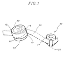
- FIG 1 there is shown a basic arrangement for a conventional helical scanning apparatus to help explain the invention, wherein a magnetic tape 20 is helically wound around a cylindrical head drum assembly 10.
- the supply slant post 12 makes the tape 20 travel downward and the take-up slant post 14 sets the tape toward the tape transporting mechanism 30 including a pinch roller 32 and a capstan 34.
- the head drum assembly 10 is divided into an upper drum part 16 and a lower drum part 18.
- the upper drum part 16 rotates counterclockwise and carries two video heads mounted on the lower surface thereof.
- the video heads are precisely 180 ° apart, opposite each other on the same diameter of the drum assembly 10. They protrude slightly to press into the surface of the tape 20.
- the lower part 18 of the drum assembly 10 is stationary and has a guide band 22 machined into the surface thereof.
- the guide band 22 serves to guide the tape 20 at an angle "eT" of, e.g., 5.93539°, to the drum assembly 10. The angle is called a "lead angle".
- the video heads alternate in recording a sequence of video fields. Since a one-half turn takes approximately 1/60 second for one field, a full turn takes 1/30 second in the NTSC standard.
- the rotation speed is 30 revolutions per second (rps), or 1800 revolutions per minute (rpm) for the head drum assembly 10.
- each video head crosses the width of the tape at a shallow angle. Each path starts near the lower edge of the tape and finishes near the upper edge thereof.
- the tape 20 is in contact with the head drum assembly 10 covering an angle of a little more than 180 and the tape 20 moves along the guide band 22 at a standard speed, e. g., 33.35 mm/sec, in a playback mode or recording mode, through the use of the tape transport mechanism 30 including the pinch roller 32 and the capstan 34.
- Magnetic recording and/or reproducing is made on diagonal paths or tracks across the tape as the tape travels across the heads at the lead angle.
- the track is inclined at an angle of, e.g., 5.9694 with respect to a longitudinal direction of the magnetic tape.
- On each diagonal track there is a single vertical field containing 262.5 horizontal lines ("262.5H") of video information, in case of the NTSC standard.
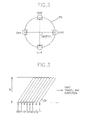
- FIG 2 shows a plan view of the head drum assembly in accordance with the invention, which is capable of performing a multi-track scanning on the tape 20.
- the drum assembly 50 includes a head arrangement having 2N number of video heads mounted thereon.
- the 2N video heads are arranged in N number of pairs with a diametrically opposite relationship and are angularly separated one another by 360 ° /2N.
- the number N corresponds to the speed multiplying factor of the tape transport mechanism 30.
- the number N is chosen to be "2"; and, therefore, only four video heads CH1, CH2, CH3 and CH4 are shown therein.
- the video heads CH1, CH2, CH3 and CH4 are angularly separated one another by 360°/2N, i.e. 90°, and the video head pairs CH1, CH3 and CH2, CH4 are arranged in pairs with a diametrically opposite relationship, respectively.
- the video heads CH1, CH2, CH3 and CH4 have one of two azimuth angles different from each other in an alternate fashion wherein a first azimuth angle is inclined in a first direction perpendicular to the head scanning direction and a second azimuth angle is inclined in a second direction opposite the first direction.
- FIG. 3 illustrates the relationship between the video heads on the drum assembly 10 and the tape 20.
- each video head sequentially lays down its corresponding track to scan the track for each 360°/2N, i.e. 90°, rotation of the head drum assembly 50. Therefore, one track is traced by each of the video heads, to thereby scan four field video information marked T1 to T4 during the period of each pass of the head drum assembly 50. Accordingly, it achieves the multi-track scanning of the magnetic tape 20 at a time during the duration of each pass of the head drum assembly 50.
- a lead angle "6 D "of the head drum assembly 50 should be changed as follows: wherein e T is the track angle inclined with respect to a longitudinal direction of the magnetic tape, W is the effective tape width, N is the speed multiplying factor and L is the distance of the tape movement per track.
- the drum diameter can be derived as: Accordingly, wherein D is the diameter of the drum assembly, N is the speed multiplying factor and 0 D is the lead angle of the drum assembly 50.
- the slant angle and the center coordinate for the slant posts 12 and 14 are also deformed to match with the configuration of the head drum assembly.
- One of the methods, for instance, is disclosed in an article by Nakamura Katsushi, "Design Method for a Tape Scanning System", Design and Estimation of a VTR Tape Scanning System, pp 11-14, published by Matsushita Electronics Co., Ltd. in Japan (April 30, 1990), which is incorporated herein by reference.
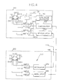
- the magnetic recording and reproducing system comprises a reproducing apparatus 100 for reproducing a prerecorded video signal on a first magnetic tape 115 loaded therein and a recording apparatus 200 for recording the reproduced video signal from the reproducing apparatus 100 on a second magnetic tape 215 loaded therein.
- the reproducing apparatus 100 includes a first rotatable head drum assembly 110 for reproducing only, and a reproducing circuit 120; and the recording apparatus 200 includes a second rotatable head drum assembly 210 for recording only, and a reproducing circuit 220.
- the first and the second rotatable head drum assemblies 110 and 210 are of the same configuration as the head drum assembly 50 described in FIG. 2.
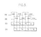
- the reproducing circuit 120 is equipped with a drum speed detector 135 for generating a pulse signal at each rotation of the drum assembly 110 and a switching pulse generator 140 for controlling the switching operation of a pair of change-over switches SW11 and SW12.
- the first square wave signal is provided as a first switching control signal to a first change-over switch SW11 for delivering video signals T1, T3, T5, T7, as shown in FIG.
- the first change-over switch SW11 selectively passes the reproduced video signals T1, T5 and T3, T7 to a first demodulator 150 by changing its movable contacts between its fixed contacts X and Y in accordance with high and low logic levels of the first control signal, respectively.
- the second change-over switch SW12 selectively passes the reproduced video signals T2, T6 and T4, T8 to a second demodulator 160 by changing its movable contact between its fixed contacts X and Y in accordance with high and low logic levels of the second control signal, respectively.
- the reproduced video signals T1, T5 and T3, T7 and the reproduced video signals T2, T6 and T4, T8 are subjected to a frequency demodulation process by the demodulators 150 and 160 and in turn provided to the recording apparatus 200 through lines 170 and 180, respectively.
- the demodulated video signals on lines 170 and 180 are supplied to a first and a second modulators 250 and 260 in the recording apparatus 200, respectively.
- Each of the first and the second modulators 250 and 260 performs a frequency modulation to produce a modulated video signal adapted for recording.
- the modulated video signals from the first and the second modulators 250 and 260 are applied to a pair of video heads CH21 and CH23 and another pair of video heads CH22 and CH24 on the second head drum assembly 210 through a pair of recording amplifiers AMP21 and AMP23 and another pair of recording amplifiers AMP22 and AMP24, respectively.
- a sequence of the reproduced video signals T1 to T8 from the first magnetic tape 115 by the reproducing video heads CH11 to CH14 in the reproducing apparatus 100 can be recorded on the second magnetic tape 215 by the recording video heads CH21 to CH24 in the recording apparatus 200.
- an audio signal may be linearly reproduced or recorded as it is because the frequency of the audio signal becomes linearly increased in proportion to the increased tape movement speed.
Landscapes
- Television Signal Processing For Recording (AREA)
- Recording Or Reproducing By Magnetic Means (AREA)
Applications Claiming Priority (2)
| Application Number | Priority Date | Filing Date | Title |
|---|---|---|---|
| KR1019930024376A KR970004613B1 (ko) | 1993-11-16 | 1993-11-16 | 고속복사전용 브이씨알 시스템 |
| KR9324376 | 1993-11-16 |
Publications (2)
| Publication Number | Publication Date |
|---|---|
| EP0653746A2 true EP0653746A2 (fr) | 1995-05-17 |
| EP0653746A3 EP0653746A3 (fr) | 1996-02-28 |
Family
ID=19368200
Family Applications (1)
| Application Number | Title | Priority Date | Filing Date |
|---|---|---|---|
| EP94118034A Withdrawn EP0653746A3 (fr) | 1993-11-16 | 1994-11-15 | Système de balayage hélicoidal multipistes. |
Country Status (4)
| Country | Link |
|---|---|
| EP (1) | EP0653746A3 (fr) |
| JP (1) | JPH07182637A (fr) |
| KR (1) | KR970004613B1 (fr) |
| CN (1) | CN1117243A (fr) |
Cited By (1)
| Publication number | Priority date | Publication date | Assignee | Title |
|---|---|---|---|---|
| DE19648502A1 (de) * | 1995-11-23 | 1997-05-28 | Samsung Electronics Co Ltd | Digitale Aufzeichnungs- und Wiedergabevorrichtung für das Hochgeschwindigkeitskopieren eines Bandes |
Family Cites Families (15)
| Publication number | Priority date | Publication date | Assignee | Title |
|---|---|---|---|---|
| JPS55105829A (en) * | 1979-02-02 | 1980-08-13 | Toshiba Corp | Reproducing system for video signal |
| JPS57183187A (en) * | 1981-05-02 | 1982-11-11 | Matsushita Electric Ind Co Ltd | Duplication system for magnetic video recording tape |
| JPS58139339A (ja) * | 1982-02-12 | 1983-08-18 | Matsushita Electric Ind Co Ltd | ビデオテ−プ複製装置 |
| CA1241739A (fr) * | 1983-04-22 | 1988-09-06 | Takeshi Ninomiya | Appareil d'enregistrement et de lecture magnetique de signaux video obtenus d'une camera video a frequence de balayage elevee |
| US4866543A (en) * | 1987-09-11 | 1989-09-12 | Electro Sound, Inc. | Multiple slave video tape reproduction system |
| AU625311B2 (en) * | 1987-09-11 | 1992-07-09 | Sony Corporation | Recording apparatus |
| US4888653A (en) * | 1987-12-28 | 1989-12-19 | Eastman Kodak Company | High speed video tape duplicator |
| JPH01208704A (ja) * | 1988-02-16 | 1989-08-22 | Victor Co Of Japan Ltd | デジタル信号記録再生装置 |
| JPH01277304A (ja) * | 1988-04-28 | 1989-11-07 | Canon Inc | 回転ヘッド型記録または再生装置 |
| JP3000575B2 (ja) * | 1988-08-16 | 2000-01-17 | 松下電器産業株式会社 | 磁気記録再生装置 |
| JPH0287302A (ja) * | 1988-09-21 | 1990-03-28 | Canon Inc | 回転ヘッド型記録及び再生装置 |
| JPH02206013A (ja) * | 1989-02-03 | 1990-08-15 | Matsushita Electric Ind Co Ltd | 磁気記録再生装置と再生コンビネーションヘッド |
| DE69029667T2 (de) * | 1989-10-04 | 1997-05-22 | Mitsubishi Electric Corp | Magnetisches Aufzeichnungs- und Wiedergabegerät |
| JPH04119079A (ja) * | 1990-09-10 | 1992-04-20 | Sony Corp | 情報信号再生方法 |
| KR960003700B1 (ko) * | 1993-11-16 | 1996-03-21 | 대우전자주식회사 | 2배속 고속복사전용 브이씨알 시스템의 데크주행계 |
-
1993
- 1993-11-16 KR KR1019930024376A patent/KR970004613B1/ko not_active Expired - Fee Related
-
1994
- 1994-11-15 EP EP94118034A patent/EP0653746A3/fr not_active Withdrawn
- 1994-11-16 CN CN94120079A patent/CN1117243A/zh active Pending
- 1994-11-16 JP JP6281985A patent/JPH07182637A/ja active Pending
Cited By (2)
| Publication number | Priority date | Publication date | Assignee | Title |
|---|---|---|---|---|
| DE19648502A1 (de) * | 1995-11-23 | 1997-05-28 | Samsung Electronics Co Ltd | Digitale Aufzeichnungs- und Wiedergabevorrichtung für das Hochgeschwindigkeitskopieren eines Bandes |
| US5986829A (en) * | 1995-11-23 | 1999-11-16 | Samsung Electronics Co., Ltd. | Digital recording and reproducing apparatus for high-speed copying of tape |
Also Published As
| Publication number | Publication date |
|---|---|
| KR970004613B1 (ko) | 1997-03-29 |
| EP0653746A3 (fr) | 1996-02-28 |
| KR950015202A (ko) | 1995-06-16 |
| JPH07182637A (ja) | 1995-07-21 |
| CN1117243A (zh) | 1996-02-21 |
Similar Documents
| Publication | Publication Date | Title |
|---|---|---|
| US4183067A (en) | Helical scan VTR with means for displacing head along track direction | |
| US3157739A (en) | Signal recording and reproducing system | |
| US4528605A (en) | Rotary magnetic head scanning control system in a magnetic recording and reproducing apparatus | |
| US4426666A (en) | Video signal recording/reproducing apparatus | |
| US4328518A (en) | Video signal, speed-change reproducing system | |
| US4246616A (en) | System for reproducing a video signal in a slow motion or still picture reproduction | |
| US4603360A (en) | Rotatable cylinder with plural heads having diverse azimuth angle gap arrangements | |
| US3391248A (en) | System and apparatus for recording and reproducing television video signals | |
| US4396954A (en) | Still mode video signal reproducing apparatus | |
| JPS628991B2 (fr) | ||
| US4535367A (en) | Magnetic record still mode reproduction apparatus and method | |
| US4314284A (en) | Video head deflection apparatus for special motion reproduction by helical scan VTR | |
| US4686584A (en) | Video signal reproduction apparatus and method having noise reduction for fast video reproduction | |
| EP0653746A2 (fr) | Système de balayage hélicoidal multipistes | |
| KR860000051B1 (ko) | 정, 역방향 슬로우 비데오 재생장치 | |
| US4463388A (en) | Rotary recording medium capable of performing special reproduction | |
| US5870240A (en) | Video cassette recorder having posts movable vertically | |
| US3215772A (en) | Magnetic recording of signals containing synchronizing information | |
| US5835301A (en) | Multi-track helical scanning system | |
| US4796128A (en) | Rotary head type reproducing apparatus | |
| USRE29999E (en) | System and apparatus for recording and reproducing television video signals | |
| KR910000187B1 (ko) | 왕복 기록 재생방법 | |
| EP0391728B1 (fr) | Appareil d'enregistrement et de reproduction magnétique à balayage hélicoidal de la bande, adapté pour post-enregistrement | |
| GB1593826A (en) | Video signal speed-change reproducing system | |
| US4782403A (en) | Recording apparatus |
Legal Events
| Date | Code | Title | Description |
|---|---|---|---|
| PUAI | Public reference made under article 153(3) epc to a published international application that has entered the european phase |
Free format text: ORIGINAL CODE: 0009012 |
|
| AK | Designated contracting states |
Kind code of ref document: A2 Designated state(s): DE FR GB NL |
|
| PUAL | Search report despatched |
Free format text: ORIGINAL CODE: 0009013 |
|
| AK | Designated contracting states |
Kind code of ref document: A3 Designated state(s): DE FR GB NL |
|
| STAA | Information on the status of an ep patent application or granted ep patent |
Free format text: STATUS: THE APPLICATION IS DEEMED TO BE WITHDRAWN |
|
| 18D | Application deemed to be withdrawn |
Effective date: 19960829 |