EP0653765B1 - Transformateur électrique polyphasé immergé auto-protégé - Google Patents
Transformateur électrique polyphasé immergé auto-protégé Download PDFInfo
- Publication number
- EP0653765B1 EP0653765B1 EP94470036A EP94470036A EP0653765B1 EP 0653765 B1 EP0653765 B1 EP 0653765B1 EP 94470036 A EP94470036 A EP 94470036A EP 94470036 A EP94470036 A EP 94470036A EP 0653765 B1 EP0653765 B1 EP 0653765B1
- Authority
- EP
- European Patent Office
- Prior art keywords
- transformer
- breaker
- sensor
- protection against
- tank
- Prior art date
- Legal status (The legal status is an assumption and is not a legal conclusion. Google has not performed a legal analysis and makes no representation as to the accuracy of the status listed.)
- Expired - Lifetime
Links
- 239000007788 liquid Substances 0.000 claims abstract description 30
- 238000004804 winding Methods 0.000 claims abstract description 14
- 230000007547 defect Effects 0.000 claims abstract description 9
- 230000007850 degeneration Effects 0.000 claims description 3
- 239000012777 electrically insulating material Substances 0.000 claims description 2
- 238000005259 measurement Methods 0.000 claims description 2
- 238000011144 upstream manufacturing Methods 0.000 claims description 2
- 238000004880 explosion Methods 0.000 abstract description 8
- 230000003412 degenerative effect Effects 0.000 abstract description 6
- 230000015556 catabolic process Effects 0.000 abstract description 2
- 230000004075 alteration Effects 0.000 abstract 1
- 239000000110 cooling liquid Substances 0.000 abstract 1
- 230000006378 damage Effects 0.000 description 11
- 239000012528 membrane Substances 0.000 description 4
- 239000000523 sample Substances 0.000 description 4
- RYGMFSIKBFXOCR-UHFFFAOYSA-N Copper Chemical compound [Cu] RYGMFSIKBFXOCR-UHFFFAOYSA-N 0.000 description 3
- 239000004020 conductor Substances 0.000 description 3
- 229910052802 copper Inorganic materials 0.000 description 3
- 239000010949 copper Substances 0.000 description 3
- 238000013461 design Methods 0.000 description 3
- 238000009826 distribution Methods 0.000 description 3
- 238000007654 immersion Methods 0.000 description 3
- 238000009413 insulation Methods 0.000 description 3
- 238000000034 method Methods 0.000 description 3
- 230000008569 process Effects 0.000 description 3
- 230000001681 protective effect Effects 0.000 description 3
- 230000002159 abnormal effect Effects 0.000 description 2
- 230000009471 action Effects 0.000 description 2
- 230000008901 benefit Effects 0.000 description 2
- 238000009835 boiling Methods 0.000 description 2
- 230000009172 bursting Effects 0.000 description 2
- 238000001514 detection method Methods 0.000 description 2
- 230000001627 detrimental effect Effects 0.000 description 2
- 230000000694 effects Effects 0.000 description 2
- 235000021183 entrée Nutrition 0.000 description 2
- 229920001342 Bakelite® Polymers 0.000 description 1
- 229910000831 Steel Inorganic materials 0.000 description 1
- XAGFODPZIPBFFR-UHFFFAOYSA-N aluminium Chemical compound [Al] XAGFODPZIPBFFR-UHFFFAOYSA-N 0.000 description 1
- 229910052782 aluminium Inorganic materials 0.000 description 1
- 230000003042 antagnostic effect Effects 0.000 description 1
- 239000004637 bakelite Substances 0.000 description 1
- 230000015572 biosynthetic process Effects 0.000 description 1
- 230000000903 blocking effect Effects 0.000 description 1
- 239000002826 coolant Substances 0.000 description 1
- 238000001816 cooling Methods 0.000 description 1
- 238000006731 degradation reaction Methods 0.000 description 1
- 238000010586 diagram Methods 0.000 description 1
- 238000009792 diffusion process Methods 0.000 description 1
- 230000004927 fusion Effects 0.000 description 1
- 230000002427 irreversible effect Effects 0.000 description 1
- 230000002045 lasting effect Effects 0.000 description 1
- 239000000463 material Substances 0.000 description 1
- 239000002480 mineral oil Substances 0.000 description 1
- 235000010446 mineral oil Nutrition 0.000 description 1
- 238000012986 modification Methods 0.000 description 1
- 230000004048 modification Effects 0.000 description 1
- 238000012544 monitoring process Methods 0.000 description 1
- 230000002688 persistence Effects 0.000 description 1
- 239000004033 plastic Substances 0.000 description 1
- 230000007480 spreading Effects 0.000 description 1
- 238000003892 spreading Methods 0.000 description 1
- 239000010959 steel Substances 0.000 description 1
- 238000005728 strengthening Methods 0.000 description 1
- 230000001960 triggered effect Effects 0.000 description 1
- 238000003466 welding Methods 0.000 description 1
Images


Classifications
-
- H—ELECTRICITY
- H01—ELECTRIC ELEMENTS
- H01F—MAGNETS; INDUCTANCES; TRANSFORMERS; SELECTION OF MATERIALS FOR THEIR MAGNETIC PROPERTIES
- H01F27/00—Details of transformers or inductances, in general
- H01F27/40—Structural association with built-in electric component, e.g. fuse
- H01F27/402—Association of measuring or protective means
- H01F2027/404—Protective devices specially adapted for fluid filled transformers
-
- H—ELECTRICITY
- H01—ELECTRIC ELEMENTS
- H01H—ELECTRIC SWITCHES; RELAYS; SELECTORS; EMERGENCY PROTECTIVE DEVICES
- H01H85/00—Protective devices in which the current flows through a part of fusible material and this current is interrupted by displacement of the fusible material when this current becomes excessive
- H01H85/02—Details
- H01H85/0241—Structural association of a fuse and another component or apparatus
- H01H2085/0291—Structural association with a current transformer
Definitions
- the present invention relates to electrical transformers self-protected immersed polyphase.
- an “immersed” transformer is a transformer of which the electrical windings and the circuit are cooled by immersion in a dielectric liquid (usually mineral oil) contained in a hermetic tank. Depending on whether the liquid dielectric fills any or part of the tank. we will be in the presence of a transformer submerged “full fill” or “partial fill”.
- protected submerged transformer a transformer of the aforementioned type comprising equipment intended for protect it from the possible consequences of damage internal, such as damage or insulation faults and the extent or persistence of which can lead to bursting of the tank.
- Such a tank strengthening solution attaches actually the effects of a rise in temperature. Moreover, it results in a significant additional cost of the transformer, and its application remains limited to devices of relatively weak power.
- the object of the invention is to propose a global solution to self-protection of submerged transformers using a equipment with autonomous and automatic operation, preserving the risk of explosion, whatever the nature of the internal defect which is the cause.
- the invention relates to a transformer submersible polyphase electric heater, placed in an airtight tank filled with dielectric liquid and provided with equipment self-protection against the risk of explosion of the tank by disconnection from the power supply network.
- the transformer according to the invention is as defined in the attached claims.
- the invention resides essentially in the design of a rupture device automatic, autonomous current flow, without intervention from outside the transformer and not resettable by the user (for security reasons).
- This action device very quick break to avoid arcing phenomena electric when opening circuits, is sensitive to both untimely current overloads and anomalies dielectric liquid reflecting the birth of a local internal defect with relatively slow evolution, at less at its beginning.
- Rapidly developing damage is characterized by large variation in the impedance of the conductor on which they appear, or act. As a rule, they lie rather at the free ends of the windings (inputs-outputs).
- This delay in transmitting the presence of a defect must be compatible with the speed of its process degeneration, i.e. of the order of a second or a few seconds, not beyond, for evolving faults the slowest.
- the temperature of the dielectric liquid does not can be used as a characteristic whose variations are monitor by the sensor.
- the speed of diffusion of the heat within the liquid mass, (in addition to capacity high heat to ensure good cooling), is far too weak indeed in view of the possible speed evolution of the defects to be detected.
- the senor used will therefore be preferably a pressure sensor, or a sound level meter, or a gas bubble detector for example, but not a probe of temperature, because the temperature of the liquid identified at except in extreme cases, the location of the probe would not be instantly representative of temperature to another place within the tank.
- the protective equipment consists of by a unit sensitive to changes in the pressure of the dielectric liquid associated with a unit sensitive to brutal current overloads called massively by the transformer on the supply network.
- the unit sensitive to changes in the pressure of the dielectric liquid essentially comprises a sensor 1 and an actuator 2.
- the sensor, mounted on a mounting plate 3 is here of the mechanical membrane type (not shown), of which the deformation, transmitted by the rod 4, is proportional at the pressure of the dielectric coolant where the membrane is submerged.
- the actuator comprises a breaker 5 and a trigger 6 linked to sensor 1 and requesting the breaker.
- the breaker is formed by two connection supports in electrically insulating plastic material, one, support 7, bearing via bakelite bases 29 distributed over the length, terminals 8, 8 ', 8' 'of output phases U, V, W of three-phase power supply network supplying the transformer, the other support 9, being fitted with terminals corresponding 10, 10 ', 10' 'entry in the windings not represented from the transformer primary.
- the output terminals 8 ... are arranged opposite the input terminals 10 ... on their respective support and cooperate with each other to ensure electrical contacts in the closed position of the switch (fig. 2a).
- the input terminals 10 ... consist of copper studs that are encircled by contacts with shaped copper blades of elastic forks forming the output terminals 8 ...
- the breaker thus designed happens to be perfectly suited to polyphase transformers to serve also of switch, tap changer.
- one of the supports may include in the immediate vicinity of each of its input terminals 10 ... copper electrical connections connected to the winding of the primary corresponding to said input terminal according to different entry points of the current in this winding. These different entry points correspond to values of different voltages applied to the phase supplying the winding.
- translatable jumpers bridging between the input terminal and both of these plates to ensure the adjustment of the transformer to the input voltage imposed on the phases by the network feed.
- These riders can advantageously be carried by a translatable rod parallel to the fixed support 9 and driven by a controlled rack and pinion system manually by an operator.
- the breaker 5 also includes an antagonistic action means elastic, here a leaf spring 11, one end of which is fixed on the mobile support 7 and the other end takes free support on a vertical surface 28 of a fixed base 12.
- an antagonistic action means elastic here a leaf spring 11, one end of which is fixed on the mobile support 7 and the other end takes free support on a vertical surface 28 of a fixed base 12.
- this spring has the role of tending in constantly placing the mobile support7 in the open position
- the movable support 7 also includes a stop for rotation lock 13 which ensures the blocking of the support in the closed position by cooperating with the trigger 6, as we will see better later.
- the stop 13 is formed by a finger fixed perpendicular to the movable support 7 and whose free end 14 is hook shaped.
- the trigger 6 consists, in the example considered, by a rigid movable element 15 leveraging and by a trigger 16.
- the movable element 15 has its fixed point 17 at one end.
- the median point 19 of the lever 15 is fixed at the end of the rod 4 of the membrane 3 of the sensor 1.
- the trigger 16 is pivotally mounted on a spring axis 20.
- a range 21 of the trigger is biased by the end free 18 of element 15, and its other bearing 22. in opposition at the first, is shaped to maintain the end crochet 14 with finger 13.
- the mobile support 7 is, as can be seen, mounted in bearings 23 provided on the fixed base 12 and which carry themselves also the fixed support 9. At the ends of this last, additional bearings 23 'are provided for hold the movable support 7 at its ends.
- These bearings as well as the fixed support 9 are, like the mobile support 7, in an electrically insulating material, for example in Bakelized paper.
- the device which has just been described operates from the as follows:
- the switch 5 In normal operation of the transformer, the switch 5 is in closed position, as shown in figs. 1 and 2a.
- a game is advantageously provided for mounting between the end 18 and the trigger. This game is set for be filled when the overpressure limit is reached.
- the end 18 requests the trigger 16, which by pivoting around its axis 20, will release the finger from retainer 13 at its other end 22.
- the movable support 7 thus unlocked, pivots around its axis in order to disconnect the output terminals 8 ... from the terminals corresponding input 10 ..., thus putting the transformer off-circuit.
- the breaker is then in an irreversible position as shown in Figure 2b.
- the entire device is placed inside of the transformer tank, so that the breaking of electrical contacts once made, it is no longer possible to reset the device without special disassembly intervention of the tank.
- the breaker can act in an extremely short time so that simultaneous opening of the circuits on the phases is not accompanied no, or as little as possible, electrical arcing phenomena when the paired connection terminals 8 ... and 10 ... move away from each other.
- This protection device is completed by a additional protection sensitive to high currents can be suddenly called on the power network by the transformer, for example due to a collapse internal impedance caused by a local short circuit, but with a significant ohmic drop.
- This protection unit is made up of, or preferably two fuses, with stepped cut-off thresholds, and mounted in cascade on each of the phases of the power supply, in series with electrical connections 8 ...- 10 ..., either downstream, or, as shown in the figures, upstream of these connections by relation to the power network.
- these fuses are also fixed on the base 24. They are are in the form of segmented cylindrical bars electrically in three independent parts between them and each relating to a phase of the three-phase supply.
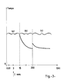
- Fuse 27 for example is intended to operate in a very high current intensity range, identified by the letter (c), going beyond 200 A.
- Fuse 26 mounted in series with the previous one, has a lower operating range (marked by the letter b), ranging from 15 to 200 A, for example.
- the threshold 15 A lower, approximately 3 to 5 times the nominal current of a distribution transformer classic 160 kVA three-phase power.
- Fuse 26 is intended to protect the transformer against fluctuations more or less lasting uncontrolled impedance primary school entrance. This can indeed drop drastically and thus make a brutal call of intensity current, relatively more moderate than that taken into account by the fuse 27 but nevertheless completely detrimental to the transformer outfit.
- the range marked (a) in the figure is the action area of the switch 5 described above. His area of intervention, as we have already explained, is that of low intensities, i.e. that of the nominal operating current of the transformer (for example 3 A.), in which the anomalies internal detrimental to the transformer may occur by very low overcurrents, which therefore pass easily overlooked.
- the retaining finger 13 can be replaced by a hollow imprint made in the support mobile 7 itself.
- the trigger 16 although advantageous, is not an essential intermediary between the lever 15 and the finger 13, which can be linked directly to each other.
- the pressure can be indirectly monitored.
- the pressure 1 can be replaced by a gas detector.
- Such a gas formation detector can be accommodated advantageously in the highest point of the tank. Yes necessary, due to the presence of baffles which may form pockets, we will use several distributed detectors at high points where such pockets are more easily susceptible to train.
- the invention also applies to any other electrical appliance similar, that is to say any device comprising electric windings immersed in a dielectric liquid and which we agree, for the sake of simplification, to name also by the general term "transformer" in the present brief.
Landscapes
- Engineering & Computer Science (AREA)
- Power Engineering (AREA)
- Coils Or Transformers For Communication (AREA)
- Housings And Mounting Of Transformers (AREA)
- Emergency Protection Circuit Devices (AREA)
- Regulation Of General Use Transformers (AREA)
- Cable Accessories (AREA)
- Gas-Insulated Switchgears (AREA)
- Fuses (AREA)
- Secondary Cells (AREA)
- Protection Of Static Devices (AREA)
- Paints Or Removers (AREA)
- Insulating Of Coils (AREA)
Description
- la figure 1 montre une vue d'ensemble du dessous d'un équipement de protection d'un transformateur en position de fermeture ;
- les figures 2 montrent, en vue latérale selon la direction A-A de la figure 1, l'équipement de protection d'abord en position de fermeture (figure 2a), puis en position d'ouverture (fig. 2b);
- la figure 3 donne les caractéristiques de fonctionnement de la batterie de fusibles de protection à l'égard des surcharges massives de courant.
- une position, dite de fermeture du rupteur, visible sur les fig. 1 et 2a, et dans laquelle les contacts entre les bornes de sortie 8... et d'entrée 10... sont assurés:
- une position décalée angulairement de la précédente avec un débattement suffisant pour éloigner les bornes d'entrée des bornes de sortie correspondantes sans risque d'arcages électriques entre-elles. Il s'agit de la position d'ouverture du rupteur, montrée sur la figure 2b.
Claims (10)
- Transformateur électrique polyphasé immergé placé dans une cuve hermétique emplie d'un liquide diélectrique et pourvue d'un équipement d'auto-protection contre les risques d'explosion de la cuve par déconnexion du réseau d'alimentation électrique, caractérisé en ce que ledit équipement est constitué par:d'une part, une unité de protection réagissant aux défectuosités internes à vitesse de dégénérescence lente et immergée dans le liquide diélectrique au sein de la cuve et comprenant:un capteur(1) sensible aux variations d'une caractéristique dudit liquide diélectrique choisie parmi celles, telle la pression, dont la mesure à un endroit quelconque est représentative de l'apparition d'une défectuosité locale n'importe où ailleurs au sein de la cuve, ledit capteur délivrant un signal en réponse à ces variations;un rupteur (5) polyphasé non-réarmable de contact entre les phases de l'alimentation électrique (u, v, w) et les enroulements primaires correspondants du transformateur;et un déclencheur (6) de commande d'ouverture du rupteur (5) sollicité par le signal délivré par le capteur (1), lorsque l'amplitude dudit signal dépasse une valeur seuil de sécurité préétablie;et d'autre part, une unité de protection à l'encontre de surcharges en courant appelées sur le réseau d'alimentation par le transformateur et comprenant au moins un fusible (27) sur chacune des phases (u, v, w) de l'alimentation.
- Transformateur selon la revendication 1, caractérisé en ce que ladite unité de protection à l'encontre de surcharges de courant est constituée, sur chacune des phases de l'alimentation électrique, par une batterie d'au moins deux fusibles (26, 27) ayant des seuils de coupure étagés et montés en série.
- Transformateur selon la revendication 1 ou 2 caractérisé en ce que ladite unité de protection à l'encontre des surcharges de courant est également immergée dans le liquide diélectrique au sein de la cuve.
- Transformateur selon la revendication 1, caractérisé en ce que le capteur (1) est de type mécanique, et délivre un signal sous forme d'une force appliquée au déclencheur (6) pour activer celui-ci lorsque ledit seuil de sécurité est dépassé.
- Transformateur selon la revendication 1 caractérisé en ce que le rupteur (5) est constitué par:deux supports (7, 9) de connexions électriques, en matière isolante de l'électricité, l'un (9) portant les bornes (10, 10', 10'') d'entrée du courant dans les enroulements du primaire du transformateur, l'autre (7) portant les bornes correspondantes (8, 8',8'') de sortie des phases de l'alimentation électrique, lesdites bornes d'entrée et de sortie étant disposées en regard les unes des autres sur leur support respectif et en contact entre elles pour assurer la liaison électrique du transformateur en position de fermeture du rupteur, l'un (9) des supports étant fixe et l'autre (7) étant monté mobile en rotation autour de son axe entre une position de fermeture et une position d'ouverture du rupteur;des moyens à action antagoniste élastique (11) tendant en permanence à placer le rupteur(5) en position d'ouverture en éloignant entre elles les bornes de sortie (8,...) de celles d'entrée (10,...) par rotation du support mobile (7);et un organe (13) de verrouillage en rotation du support mobile (7) assurant le maintien du rupteur (5) en position de fermeture en étant en prise dans le déclencheur (2).
- Transformateur selon la revendication 5, caractérisé en ce que sur le support mobile (7) les bornes (8) sont situées sur des embases porteuses (29) qui les éloignent de l'axe de rotation du support.
- Transformateur selon la revendication 5, caractérisé en ce que ledit support mobile (7) est monté en rotation dans des paliers (23) qui maintiennent également le support fixe (9), lesdits paliers étant portés par une embase (12) fixée à un plateau de base (24) et portant le déclencheur (6) et offrant une surface d'appui (28) aux moyens à action antagoniste élastique (11).
- Transformateur selon la revendication 1, caractérisé en ce que le déclencheur (6) est formé par un élément mobile (15) sollicité par le capteur (1), et par une gâchette (16) pivotante à ressort de retour (20) dont une extrémité (22) coopère avec l'organe (13) de verrouillage de la rotation du support mobile (7) pour maintenir le rupteur (5) en position de fermeture, et l'autre extrémité (21) coopère avec ledit élément mobile (15).
- Transformateur selon la revendication 1 ou 2 , caractérisé en ce que ladite unité de protection à l'encontre des surcharges de courant est montée en amont de l'unité de protection sensible aux caractéristiques du liquide diélectrique, par rapport à l'alimentation électrique.
- Transformateur selon la revendication 5 caractérisé en ce que le rupteur comporte des moyens de commutation permettant d'adapter simultanément les points d'entrée du courant dans les enroulements du primaire à la valeur de la tension appliquée par le réseau électrique sur chaque phase de l'alimentation.
Applications Claiming Priority (2)
| Application Number | Priority Date | Filing Date | Title |
|---|---|---|---|
| FR9313700A FR2712730B1 (fr) | 1993-11-15 | 1993-11-15 | Transformateur électrique imergé protégé. |
| FR9313700 | 1993-11-15 |
Publications (2)
| Publication Number | Publication Date |
|---|---|
| EP0653765A1 EP0653765A1 (fr) | 1995-05-17 |
| EP0653765B1 true EP0653765B1 (fr) | 1999-12-15 |
Family
ID=9452921
Family Applications (1)
| Application Number | Title | Priority Date | Filing Date |
|---|---|---|---|
| EP94470036A Expired - Lifetime EP0653765B1 (fr) | 1993-11-15 | 1994-11-14 | Transformateur électrique polyphasé immergé auto-protégé |
Country Status (9)
| Country | Link |
|---|---|
| EP (1) | EP0653765B1 (fr) |
| AT (1) | ATE187843T1 (fr) |
| DE (1) | DE69422142T2 (fr) |
| EG (1) | EG20461A (fr) |
| ES (1) | ES2142393T3 (fr) |
| FR (1) | FR2712730B1 (fr) |
| MA (1) | MA23366A1 (fr) |
| OA (1) | OA09967A (fr) |
| ZA (1) | ZA948692B (fr) |
Families Citing this family (7)
| Publication number | Priority date | Publication date | Assignee | Title |
|---|---|---|---|---|
| FR2730357A1 (fr) * | 1995-02-08 | 1996-08-09 | Alsthom Gec | Systeme permettant de deconnecter electriquement de son alimentation un appareillage electrique a isolation par un dielectrique liquide |
| FR2747245B1 (fr) * | 1996-04-04 | 1998-05-15 | Gec Alsthom T & D Sa | Systeme de protection d'un transformateur de distribution triphase a isolation dans un dielectrique liquide |
| FI102329B (fi) | 1997-02-06 | 1998-11-13 | Abb Transmit Oy | Kytkin sähköisen laitteen erottamiseksi sähköverkosta |
| FR2782409B1 (fr) * | 1998-08-14 | 2002-11-29 | Schneider Electric Ind Sa | Transformateur immerge auto-protege par un dispositif incluant un disjoncteur et des fusibles |
| FR2822601B1 (fr) * | 2001-03-21 | 2004-12-24 | Transfix Toulon Soc Nouv | Poste de transformation evolutif pour reseaux en coupure d'artere |
| ES2527091T3 (es) | 2007-12-28 | 2015-01-20 | Constructora De Transformadores De Distribución Cotradis, S.L.U. | Equipo eléctrico para red de distribución con sistema de detección, desconexión y eliminación de faltas |
| FR2942353B1 (fr) * | 2009-02-19 | 2011-06-17 | Transfix Toulon Sa Soc Nouv | Procede, dispositif et systeme de protection d'un appareil electrique, ainsi que transformateur et poste comportant un tel dispositif ou systeme |
Family Cites Families (3)
| Publication number | Priority date | Publication date | Assignee | Title |
|---|---|---|---|---|
| US4223364A (en) * | 1978-05-25 | 1980-09-16 | Sangster Harold L | Pressure and temperature responsive protective devices |
| US4435690A (en) * | 1982-04-26 | 1984-03-06 | Rte Corporation | Primary circuit breaker |
| DE3543584A1 (de) * | 1985-12-10 | 1987-06-11 | Volta Werke Electricitaet | Transformator mit sicherungseinrichtung |
-
1993
- 1993-11-15 FR FR9313700A patent/FR2712730B1/fr not_active Expired - Fee Related
-
1994
- 1994-11-03 ZA ZA948692A patent/ZA948692B/xx unknown
- 1994-11-08 MA MA23690A patent/MA23366A1/fr unknown
- 1994-11-11 OA OA60581A patent/OA09967A/fr unknown
- 1994-11-12 EG EG71794A patent/EG20461A/fr active
- 1994-11-14 ES ES94470036T patent/ES2142393T3/es not_active Expired - Lifetime
- 1994-11-14 DE DE69422142T patent/DE69422142T2/de not_active Expired - Lifetime
- 1994-11-14 AT AT94470036T patent/ATE187843T1/de not_active IP Right Cessation
- 1994-11-14 EP EP94470036A patent/EP0653765B1/fr not_active Expired - Lifetime
Also Published As
| Publication number | Publication date |
|---|---|
| OA09967A (fr) | 1995-12-11 |
| DE69422142T2 (de) | 2000-08-24 |
| MA23366A1 (fr) | 1995-07-01 |
| FR2712730B1 (fr) | 1995-12-29 |
| DE69422142D1 (de) | 2000-01-20 |
| EP0653765A1 (fr) | 1995-05-17 |
| FR2712730A1 (fr) | 1995-05-24 |
| ATE187843T1 (de) | 2000-01-15 |
| ES2142393T3 (es) | 2000-04-16 |
| EG20461A (fr) | 1999-05-31 |
| ZA948692B (en) | 1995-07-03 |
Similar Documents
| Publication | Publication Date | Title |
|---|---|---|
| EP1304785B1 (fr) | Système de protection d'un transformateur de distribution polyphasé à isolation dans un diélectrique liquide, comportant au moins un interrupteur sectionneur de phase | |
| EP0258090B1 (fr) | Déclencheur statique d'un disjoncteur électrique à indicateur d'usure des contacts | |
| EP3319194B1 (fr) | Dispositif de protection contre les surtensions transitoires | |
| FR2772524A1 (fr) | Dispositif de protection contre des surintensites, notamment pour la protection rearmable d'un interrupteur controle | |
| WO2017042321A1 (fr) | Dispositif de protection pour un circuit électrique, circuit électrique équipé d'un tel dispositif et procédé de protection d'un tel circuit électrique | |
| BE1012970A5 (fr) | Coupe-circuit pour debrancher un appareil electrique du reseau electrique. | |
| EP0653765B1 (fr) | Transformateur électrique polyphasé immergé auto-protégé | |
| EP2513942B1 (fr) | Ensemble de protection contre les surtensions | |
| EP0981140B1 (fr) | Transformateur immerge auto-protege par un dispositif incluant un disjoncteur et des fusibles | |
| CA2201770A1 (fr) | Systeme de protection d'un transformateur de distribution triphase a isolation dans un dielectrique liquide | |
| EP3244504A1 (fr) | Dispositif de protection contre les surtensions transitoires | |
| EP2221838B1 (fr) | Procédé, dispositif et système de protection d'un appareil électrique, ainsi que transformateur et poste comportant un tel dispositif ou système | |
| EP1051099B1 (fr) | Thermostat a thermistance et interrupteur-relais pour resistances chauffantes d'appareil electromenager | |
| EP1102379B1 (fr) | Système de protection d'un transformateur de distribution triphasé à isolation dans un diélectrique liquide comportant un micro-sectionneur | |
| FR2512269A1 (fr) | Fusible electrique et son element fusible incorpore | |
| EP1267368B1 (fr) | Transformateur de distribution auto-protégé par un disjoncteur déclenchant sur court-circuit secondaire | |
| EP0736945B1 (fr) | Déconnecteur-limiteur de protection pour transformateurs électriques triphasés | |
| EP1156704B1 (fr) | Dispositif formant thermoplongeur pouvant être utilisé notammant dans un radiateur de chauffage à circulation d'eau | |
| FR3064414B1 (fr) | Appareil de coupure de courant electrique comportant un afficheur a cristaux liquides et un mecanisme presseur | |
| EP0027757A1 (fr) | Dispositif de protection pour ligne d'énergie électrique | |
| FR2999794A1 (fr) | Dispositif de declenchement thermique et appareil de coupure du courant comportant un tel dispositif, en particulier un disjoncteur de branchement. | |
| WO2004102764A1 (fr) | Dispositif de protection d'un transformateur de distribution multiphase, a isolation dans un dielectrique liquide | |
| EP2449570B1 (fr) | Module de protection contre les surtensions et ensemble de protection comportant un tel module | |
| FR2764130A1 (fr) | Declencheur d'auto-protection pour transformateur electrique immerge | |
| FR2730357A1 (fr) | Systeme permettant de deconnecter electriquement de son alimentation un appareillage electrique a isolation par un dielectrique liquide |
Legal Events
| Date | Code | Title | Description |
|---|---|---|---|
| PUAI | Public reference made under article 153(3) epc to a published international application that has entered the european phase |
Free format text: ORIGINAL CODE: 0009012 |
|
| AK | Designated contracting states |
Kind code of ref document: A1 Designated state(s): AT BE CH DE DK ES FR GB GR IE IT LI LU MC NL PT SE |
|
| 17P | Request for examination filed |
Effective date: 19951106 |
|
| GRAG | Despatch of communication of intention to grant |
Free format text: ORIGINAL CODE: EPIDOS AGRA |
|
| GRAG | Despatch of communication of intention to grant |
Free format text: ORIGINAL CODE: EPIDOS AGRA |
|
| GRAH | Despatch of communication of intention to grant a patent |
Free format text: ORIGINAL CODE: EPIDOS IGRA |
|
| 17Q | First examination report despatched |
Effective date: 19990427 |
|
| GRAH | Despatch of communication of intention to grant a patent |
Free format text: ORIGINAL CODE: EPIDOS IGRA |
|
| GRAA | (expected) grant |
Free format text: ORIGINAL CODE: 0009210 |
|
| AK | Designated contracting states |
Kind code of ref document: B1 Designated state(s): AT BE CH DE DK ES FR GB GR IE IT LI LU MC NL PT SE |
|
| PG25 | Lapsed in a contracting state [announced via postgrant information from national office to epo] |
Ref country code: SE Free format text: THE PATENT HAS BEEN ANNULLED BY A DECISION OF A NATIONAL AUTHORITY Effective date: 19991215 Ref country code: NL Free format text: LAPSE BECAUSE OF FAILURE TO SUBMIT A TRANSLATION OF THE DESCRIPTION OR TO PAY THE FEE WITHIN THE PRESCRIBED TIME-LIMIT Effective date: 19991215 Ref country code: GR Free format text: LAPSE BECAUSE OF NON-PAYMENT OF DUE FEES Effective date: 19991215 Ref country code: AT Free format text: LAPSE BECAUSE OF FAILURE TO SUBMIT A TRANSLATION OF THE DESCRIPTION OR TO PAY THE FEE WITHIN THE PRESCRIBED TIME-LIMIT Effective date: 19991215 |
|
| REF | Corresponds to: |
Ref document number: 187843 Country of ref document: AT Date of ref document: 20000115 Kind code of ref document: T |
|
| REG | Reference to a national code |
Ref country code: CH Ref legal event code: EP |
|
| REF | Corresponds to: |
Ref document number: 69422142 Country of ref document: DE Date of ref document: 20000120 |
|
| REG | Reference to a national code |
Ref country code: IE Ref legal event code: FG4D |
|
| ITF | It: translation for a ep patent filed | ||
| PG25 | Lapsed in a contracting state [announced via postgrant information from national office to epo] |
Ref country code: PT Free format text: LAPSE BECAUSE OF FAILURE TO SUBMIT A TRANSLATION OF THE DESCRIPTION OR TO PAY THE FEE WITHIN THE PRESCRIBED TIME-LIMIT Effective date: 20000315 Ref country code: DK Free format text: LAPSE BECAUSE OF FAILURE TO SUBMIT A TRANSLATION OF THE DESCRIPTION OR TO PAY THE FEE WITHIN THE PRESCRIBED TIME-LIMIT Effective date: 20000315 |
|
| GBT | Gb: translation of ep patent filed (gb section 77(6)(a)/1977) |
Effective date: 20000309 |
|
| REG | Reference to a national code |
Ref country code: ES Ref legal event code: FG2A Ref document number: 2142393 Country of ref document: ES Kind code of ref document: T3 |
|
| NLV1 | Nl: lapsed or annulled due to failure to fulfill the requirements of art. 29p and 29m of the patents act | ||
| PLBE | No opposition filed within time limit |
Free format text: ORIGINAL CODE: 0009261 |
|
| STAA | Information on the status of an ep patent application or granted ep patent |
Free format text: STATUS: NO OPPOSITION FILED WITHIN TIME LIMIT |
|
| PG25 | Lapsed in a contracting state [announced via postgrant information from national office to epo] |
Ref country code: LU Free format text: LAPSE BECAUSE OF NON-PAYMENT OF DUE FEES Effective date: 20001114 |
|
| PG25 | Lapsed in a contracting state [announced via postgrant information from national office to epo] |
Ref country code: IE Free format text: LAPSE BECAUSE OF NON-PAYMENT OF DUE FEES Effective date: 20001116 |
|
| 26N | No opposition filed | ||
| PG25 | Lapsed in a contracting state [announced via postgrant information from national office to epo] |
Ref country code: MC Free format text: THE PATENT HAS BEEN ANNULLED BY A DECISION OF A NATIONAL AUTHORITY Effective date: 20001130 |
|
| REG | Reference to a national code |
Ref country code: IE Ref legal event code: FD4D |
|
| REG | Reference to a national code |
Ref country code: GB Ref legal event code: IF02 |
|
| PGFP | Annual fee paid to national office [announced via postgrant information from national office to epo] |
Ref country code: DE Payment date: 20101118 Year of fee payment: 17 |
|
| PGFP | Annual fee paid to national office [announced via postgrant information from national office to epo] |
Ref country code: IT Payment date: 20101115 Year of fee payment: 17 |
|
| PGFP | Annual fee paid to national office [announced via postgrant information from national office to epo] |
Ref country code: CH Payment date: 20111114 Year of fee payment: 18 Ref country code: ES Payment date: 20111216 Year of fee payment: 18 |
|
| REG | Reference to a national code |
Ref country code: DE Ref legal event code: R084 Ref document number: 69422142 Country of ref document: DE Effective date: 20111228 |
|
| PGFP | Annual fee paid to national office [announced via postgrant information from national office to epo] |
Ref country code: BE Payment date: 20111114 Year of fee payment: 18 |
|
| PGFP | Annual fee paid to national office [announced via postgrant information from national office to epo] |
Ref country code: FR Payment date: 20121205 Year of fee payment: 19 |
|
| PGFP | Annual fee paid to national office [announced via postgrant information from national office to epo] |
Ref country code: GB Payment date: 20121114 Year of fee payment: 19 |
|
| BERE | Be: lapsed |
Owner name: S.A. *FRANCE TRANSFO Effective date: 20121130 |
|
| REG | Reference to a national code |
Ref country code: CH Ref legal event code: PL |
|
| PG25 | Lapsed in a contracting state [announced via postgrant information from national office to epo] |
Ref country code: LI Free format text: LAPSE BECAUSE OF NON-PAYMENT OF DUE FEES Effective date: 20121130 Ref country code: CH Free format text: LAPSE BECAUSE OF NON-PAYMENT OF DUE FEES Effective date: 20121130 |
|
| PG25 | Lapsed in a contracting state [announced via postgrant information from national office to epo] |
Ref country code: BE Free format text: LAPSE BECAUSE OF NON-PAYMENT OF DUE FEES Effective date: 20121130 Ref country code: IT Free format text: LAPSE BECAUSE OF NON-PAYMENT OF DUE FEES Effective date: 20121114 |
|
| REG | Reference to a national code |
Ref country code: DE Ref legal event code: R119 Ref document number: 69422142 Country of ref document: DE Effective date: 20130601 |
|
| PG25 | Lapsed in a contracting state [announced via postgrant information from national office to epo] |
Ref country code: DE Free format text: LAPSE BECAUSE OF NON-PAYMENT OF DUE FEES Effective date: 20130601 |
|
| REG | Reference to a national code |
Ref country code: ES Ref legal event code: FD2A Effective date: 20140305 |
|
| PG25 | Lapsed in a contracting state [announced via postgrant information from national office to epo] |
Ref country code: ES Free format text: LAPSE BECAUSE OF NON-PAYMENT OF DUE FEES Effective date: 20121115 |
|
| GBPC | Gb: european patent ceased through non-payment of renewal fee |
Effective date: 20131114 |
|
| REG | Reference to a national code |
Ref country code: FR Ref legal event code: ST Effective date: 20140731 |
|
| PG25 | Lapsed in a contracting state [announced via postgrant information from national office to epo] |
Ref country code: GB Free format text: LAPSE BECAUSE OF NON-PAYMENT OF DUE FEES Effective date: 20131114 Ref country code: FR Free format text: LAPSE BECAUSE OF NON-PAYMENT OF DUE FEES Effective date: 20131202 |