EP0653810B1 - Elektrische Verbindung für zweiadrigen leitende Elastomerleiste - Google Patents
Elektrische Verbindung für zweiadrigen leitende Elastomerleiste Download PDFInfo
- Publication number
- EP0653810B1 EP0653810B1 EP94306611A EP94306611A EP0653810B1 EP 0653810 B1 EP0653810 B1 EP 0653810B1 EP 94306611 A EP94306611 A EP 94306611A EP 94306611 A EP94306611 A EP 94306611A EP 0653810 B1 EP0653810 B1 EP 0653810B1
- Authority
- EP
- European Patent Office
- Prior art keywords
- connector
- tube
- core support
- gripper arms
- core
- Prior art date
- Legal status (The legal status is an assumption and is not a legal conclusion. Google has not performed a legal analysis and makes no representation as to the accuracy of the status listed.)
- Expired - Lifetime
Links
- 239000004020 conductor Substances 0.000 claims description 44
- 230000006835 compression Effects 0.000 claims description 3
- 238000007906 compression Methods 0.000 claims description 3
- 230000014759 maintenance of location Effects 0.000 description 8
- 238000000638 solvent extraction Methods 0.000 description 4
- OKTJSMMVPCPJKN-UHFFFAOYSA-N Carbon Chemical compound [C] OKTJSMMVPCPJKN-UHFFFAOYSA-N 0.000 description 3
- 229910052799 carbon Inorganic materials 0.000 description 3
- 230000000295 complement effect Effects 0.000 description 3
- 230000037431 insertion Effects 0.000 description 3
- 238000003780 insertion Methods 0.000 description 3
- 208000027418 Wounds and injury Diseases 0.000 description 2
- 230000006378 damage Effects 0.000 description 2
- 208000014674 injury Diseases 0.000 description 2
- 238000001514 detection method Methods 0.000 description 1
- 239000011159 matrix material Substances 0.000 description 1
- 238000000465 moulding Methods 0.000 description 1
- 230000000630 rising effect Effects 0.000 description 1
Images





Classifications
-
- H—ELECTRICITY
- H01—ELECTRIC ELEMENTS
- H01R—ELECTRICALLY-CONDUCTIVE CONNECTIONS; STRUCTURAL ASSOCIATIONS OF A PLURALITY OF MUTUALLY-INSULATED ELECTRICAL CONNECTING ELEMENTS; COUPLING DEVICES; CURRENT COLLECTORS
- H01R13/00—Details of coupling devices of the kinds covered by groups H01R12/70 or H01R24/00 - H01R33/00
- H01R13/46—Bases; Cases
-
- H—ELECTRICITY
- H01—ELECTRIC ELEMENTS
- H01R—ELECTRICALLY-CONDUCTIVE CONNECTIONS; STRUCTURAL ASSOCIATIONS OF A PLURALITY OF MUTUALLY-INSULATED ELECTRICAL CONNECTING ELEMENTS; COUPLING DEVICES; CURRENT COLLECTORS
- H01R13/00—Details of coupling devices of the kinds covered by groups H01R12/70 or H01R24/00 - H01R33/00
- H01R13/58—Means for relieving strain on wire connection, e.g. cord grip, for avoiding loosening of connections between wires and terminals within a coupling device terminating a cable
- H01R13/5804—Means for relieving strain on wire connection, e.g. cord grip, for avoiding loosening of connections between wires and terminals within a coupling device terminating a cable comprising a separate cable clamping part
- H01R13/5812—Means for relieving strain on wire connection, e.g. cord grip, for avoiding loosening of connections between wires and terminals within a coupling device terminating a cable comprising a separate cable clamping part the cable clamping being achieved by mounting the separate part on the housing of the coupling device
-
- E—FIXED CONSTRUCTIONS
- E05—LOCKS; KEYS; WINDOW OR DOOR FITTINGS; SAFES
- E05F—DEVICES FOR MOVING WINGS INTO OPEN OR CLOSED POSITION; CHECKS FOR WINGS; WING FITTINGS NOT OTHERWISE PROVIDED FOR, CONCERNED WITH THE FUNCTIONING OF THE WING
- E05F15/00—Power-operated mechanisms for wings
- E05F15/40—Safety devices, e.g. detection of obstructions or end positions
- E05F15/42—Detection using safety edges
- E05F15/44—Detection using safety edges responsive to changes in electrical conductivity
- E05F15/443—Detection using safety edges responsive to changes in electrical conductivity specially adapted for vehicle windows or roofs
-
- H—ELECTRICITY
- H01—ELECTRIC ELEMENTS
- H01R—ELECTRICALLY-CONDUCTIVE CONNECTIONS; STRUCTURAL ASSOCIATIONS OF A PLURALITY OF MUTUALLY-INSULATED ELECTRICAL CONNECTING ELEMENTS; COUPLING DEVICES; CURRENT COLLECTORS
- H01R24/00—Two-part coupling devices, or either of their cooperating parts, characterised by their overall structure
- H01R24/28—Coupling parts carrying pins, blades or analogous contacts and secured only to wire or cable
-
- E—FIXED CONSTRUCTIONS
- E05—LOCKS; KEYS; WINDOW OR DOOR FITTINGS; SAFES
- E05Y—INDEXING SCHEME ASSOCIATED WITH SUBCLASSES E05D AND E05F, RELATING TO CONSTRUCTION ELEMENTS, ELECTRIC CONTROL, POWER SUPPLY, POWER SIGNAL OR TRANSMISSION, USER INTERFACES, MOUNTING OR COUPLING, DETAILS, ACCESSORIES, AUXILIARY OPERATIONS NOT OTHERWISE PROVIDED FOR, APPLICATION THEREOF
- E05Y2600/00—Mounting or coupling arrangements for elements provided for in this subclass
- E05Y2600/40—Mounting location; Visibility of the elements
-
- E—FIXED CONSTRUCTIONS
- E05—LOCKS; KEYS; WINDOW OR DOOR FITTINGS; SAFES
- E05Y—INDEXING SCHEME ASSOCIATED WITH SUBCLASSES E05D AND E05F, RELATING TO CONSTRUCTION ELEMENTS, ELECTRIC CONTROL, POWER SUPPLY, POWER SIGNAL OR TRANSMISSION, USER INTERFACES, MOUNTING OR COUPLING, DETAILS, ACCESSORIES, AUXILIARY OPERATIONS NOT OTHERWISE PROVIDED FOR, APPLICATION THEREOF
- E05Y2900/00—Application of doors, windows, wings or fittings thereof
- E05Y2900/50—Application of doors, windows, wings or fittings thereof for vehicles
- E05Y2900/53—Type of wing
- E05Y2900/55—Windows
-
- H—ELECTRICITY
- H01—ELECTRIC ELEMENTS
- H01R—ELECTRICALLY-CONDUCTIVE CONNECTIONS; STRUCTURAL ASSOCIATIONS OF A PLURALITY OF MUTUALLY-INSULATED ELECTRICAL CONNECTING ELEMENTS; COUPLING DEVICES; CURRENT COLLECTORS
- H01R2103/00—Two poles
Definitions
- This invention relates to an electrical connector for making electrical connection to spaced conductive cores disposed within a flexible tube.
- One such detection means designed for this very purpose comprises a flexible hollow tube having a pair of spaced apart flexible conductors extending along the inner wall of the tube. This tube would be placed proximate the upper sill of the automobile window frame, whereby an obstacle captured between the closing window and the window frame, would compress the flexible tube thereby producing contact between the flexible conductors therein. These conductors would be electrically connected to the electrical motor and contact therebetween would cause appropriate command of the motor.
- this known tube includes carbon conductors, which are difficult to provide an interconnection thereto as the carbon conductors can neither be adequately crimped or soldered.
- the object of this invention therefore, is to provide a reliable electrical connector for making electrical connection between a flexible twin core conductor tube and electrical conducting wires.
- a further object of this invention is to provide an electrical connector for making connection to conductors mounted in a flexible tube that is easily assembled and cost-effective, yet reliable.
- the present invention consists in an electrical connector as defined in claim 1.
- EP-A- 0 383 671 discloses an electrical connector according to the preamble of claim 1.
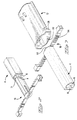
- an electrical connector 2 is shown connected to a twin core flexible tube conductor 4 comprising an elastomeric outer tube 6 and a pair of spaced apart opposed flexible core conductors 8 attached to an inner wall 10 of the tube 6.
- the connector 2 comprises an insulative housing 12, a pair of electrical conducting terminals 14 and a separate core support member 16.
- the connector housing 12 comprises a conductor connection section 18 having a conductor receiving cavity 20, and a complementary receiving section 22 having a connection receiving cavity 24, a connector housing shell 25 surrounding the cavities 20, 24, and a partitioning wall 26 separating the cavities 20 and 24.
- U-shaped retaining members 28 extending outwardly on either side of the connector housing shell 25, the retention members 28 having an inner guide surface 30 and a rearward retention face 32.
- a mounting member 34 having a resilient projection 36 for securely mounting the connector to a bracket of some structure such as an automobile door panel.
- the terminals 14 comprise tab portions 38 extending into the housing cavity 24 from the partitioning wall 26, attached to mid-portions 40 (see Figure 1) which are in-moulded to the partitioning wall 26, the mid portions 40 extending into core contact pins 41 that project into the cavity section 20. Due to the moulding of the partitioning wall 26 over the contact mid-sections 40, the terminals 14 are securely mounted to the housing 12 and the conductor receiving cavity 20 is perfectly sealed off from the complementary connector receiving cavity 24.
- the core support member 16 comprises a central elongate core section 42 having a pair of opposed concave surfaces 44 profiled to receive the flexible core conductors 8 snugly thereagainst, and pin terminal receiving grooves 46 extending from a pin receiving end 48 of the core section 42 to an approximately middle section thereof, the grooves 46 cut into the concave surfaces 44.
- a flange 50 Extending radially outwards from the pin receiving end 48, is a flange 50 having pin receiving cavities 52 therethrough providing access to the grooves 46.
- Gripper means 54 in the form of long arms 55 disposed symmetrically about the flange 50 are attached integrally thereto via thin flexible hinges 56, the arms 54 having a plurality of juxtaposed strain relief projections 58 jutting out of an inner surface 64 thereof. Extending from the arms 54 are latching means 66 cooperable with the connector housing retention flanges 28 for retaining the connector housing thereto.
- the latching means 66 comprise a latching projection 68 and a tool receiving release member 70.
- the core member 16 is first mounted to the conductor 4 by inserting the core section 42 into a cavity area 71 defined by the inner contour of the flexible tube 6 and the conductors 8, whereby the core section 42 is profiled to substantially fill this cavity area 71. Insertion of the core member 16 is effectuated until the flange portion 50 thereof abuts the end of the conducting tube 4 as shown in Figure 3.
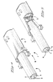
- the assembled conductor tube 4 and core support member 16 can then be aligned to the conductor receiving cavity 20 of the connector housing 12 and then approached together until the core member retention arms 54 abut the housing flange members 28.
- the gripper arms 54 continues urging of the conductor tube 4 towards the housing cavity 20, causes the gripper arms 54 to pivot about the flexible hinges 56 thereby biasing the arms 54 against the flexible tube 6 and allowing the conductor 4 to enter the cavity 20 as shown in Figures 4 and 5.
- the pin contacts 41 are inserted through the flange holes 52 and along the grooves 46 of the core support member 16.
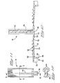
- the pin contacts 41 are of greater thickness than the height of the groove 46 thus projecting outwards of the concave surfaces 44 against which the resilient conductors 8 are biased (see Figure 1).
- the conductors 8 are constituted of a conducting material such as carbon integrated within a flexible elastomeric matrix which results in a very flexible conductor that is resiliently compressed about the projecting portion of the pin contacts 41 that are disposed between the core section 42 and conductors 8. Resilient urging of the conductors 8 against the pin contacts 41 ensures good electrical contact therebetween.
- Opposed inner side wall sections 72 adjacent the core member gripper means 54 ensure that the arms 54 are biased against the tube 6 such that the strain relief projections dig thereinto thereby securely retaining the connector 2 to the tube conductor 4 against a tensile force therealong.
- the core member section 42 not only prevents collapsing of the tube 4 in response to the biasing together of the gripper arms 54, but also provides a supporting means enabling compression of the conductors 8 against the pin contact 41 for good electrical connection therebetween.
- an adequate tool can be placed within the tool receiving release member 70, followed by squeezing the arms 54 together until the latching projections 58 are biased below the connector flange inner surface 30 thereby enabling retraction of the connector housing 12 therefrom.
- the assembled electrical connector and tube conductor as shown in Figures 6 and 7, can be coupled to a complementary connector that is electrically connected to electrical circuitry commanding the motor of an automobile window for example.
- a certain portion of the tube conductor 4 can be placed proximate the sill of the window frame such that an object captured between the rising window and the window frame will squeeze the flexible tube 6 until the conductors 8 enter into electrical contact with each other, thereby affecting the electrical motor command circuitry which can be appropriately designed for safe operation thereof.
- the connector housing 12 can be provided with mounting means 34 as shown in Figure 17 for securely latching the connector 2 to the body work of a vehicle for example.
- the present embodiment provides a reliable connector for making electrical connection between a flexible twin core tube conductor and electrical circuitry, the connector being rapidly and easily assembled yet comprising very secure retention means: by the bias of the gripper arms and strain relief projections that clasp the conductors and tube against an inner core member. Clasping of the connector retention arms against the tube conductor compresses the flexible core conductors against terminals of the connector for good electrical connection therebetween.
Landscapes
- Details Of Connecting Devices For Male And Female Coupling (AREA)
- Connector Housings Or Holding Contact Members (AREA)
Claims (13)
- Elektrischer Verbinder (2) zur Herstellung einer elektrischen Verbindung mit einem Röhrenleiter (4) mit beabstandeten leitenden Adern (8), die in einer Elastomerröhre (6) angeordnet sind, wobei der Verbinder (2) ein Isoliergehäuse (12) und darin befestigte Anschlüsse (14) umfaßt, wobei der Verbinder auch einen zwischen die leitenden Adern (8) einfügbaren Adernstützteil (42) und ein über dem Adernstützteil (42) zum Festhalten der Röhre (6) dazwischen angeordnetes Greifermittel (54) umfaßt; dadurch gekennzeichnet, daß das Greifermittel Greiferarme (54) umfaßt, die gelenkig am Adernstützteil (42) angebracht sind, der in den elektrischen Verbinder (2) einfügbar ist und an diesem verriegelbar ist, woraufhin Stiftkontakte (41) im elektrischen Verbinder (2) elektrisch mit den leitenden Adern (8) verbunden sind.
- Verbinder nach Anspruch 1, dadurch gekennzeichnet, daß die Greiferarme (54) und die Adernstütze (42) einstückig sind.
- Verbinder nach Anspruch 1 oder 2, dadurch gekennzeichnet, daß die Adernstütze (42) so profiliert ist, daß sie im wesentlichen einen durch den Leerraum zwischen den leitenden Adern und mit der Außenröhre (6) entlang der Länge der Adernstütze (42) definierten Hohlraumbereich (71) anfüllt.
- Verbinder nach Anspruch 1, 2 oder 3, dadurch gekennzeichnet, daß die Anschlüsse (14) am Verbindergehäuse (12) angeformt sind.
- Verbinder nach einem vorhergehenden Anspruch, dadurch gekennzeichnet, daß die Anschlüsse (14) einen Adernkontaktteil (41) mit zwischen den Adernstützteil (42) und die leitenden Adern (8) einfügbaren Stiftkontakten (41) aufweisen.
- Verbinder nach Anspruch 5, dadurch gekennzeichnet, daß der Adernstützteil (42) Längsrillen (46) zur Aufnahme der Stiftkontakte (41) aufweist.
- Verbinder nach einem vorhergehenden Anspruch, dadurch gekennzeichnet, daß die Greiferarme (54) Riegelmittel (66) umfassen, die mit Verbindergehäuseriegelmitteln (28) zur Befestigung des Verbindergehäuses daran zusammenwirken können.
- Verbinder nach Anspruch 7, dadurch gekennzeichnet, daß die Riegelmittel (66) einen verjüngten Vorsprung (68, 69) neben Enden der Greiferarme (54) umfassen, und die Verbinderriegelmittel an einem hinteren Ende derselben eine Klammer (28) umfassen, die über den verjüngten Vorsprung (68, 69) schiebbar ist und damit die Greiferarme (54) nachgiebig nach innen gegen die nachgiebige Kompression des Röhrenleiters (4) vorspannt, bis der verjüngte Vorsprung (68, 69) hinter einer Schulter (32) der Klammer (28) verriegelt ist.
- Verbinder nach einem vorhergehenden Anspruch, dadurch gekennzeichnet, daß die Greiferarme (54) mindestens einen längs der Röhre (4) ausstreckbaren Arm (54) umfassen, der entlang einer Innenfläche Vorsprünge (58) aufweist, die quer zur Längsrichtung liegen, um in die Röhre (4) einzugreifen und den Greiferarm (54) entgegen einer Längsziehkraft daran festzuhalten.
- Verbinder nach Anspruch 9, dadurch gekennzeichnet, daß die Greiferarme (54) zwei im wesentlichen symmetrisch um die Adernstütze (42) angeordnete Greiferarme (54) umfassen.
- Verbinder nach einem vorhergehenden Anspruch, dadurch gekennzeichnet, daß das Verbindergehäuse (12) eine sich um und entlang der Adernkontaktstifte (41) der Anschlüsse (14) erstreckende Außenschale (25) umfaßt, die so profiliert ist, daß sie darin die zusammengebauten Greiferarme (54), dem Röhrenleiter (4) und die Adernstütze (42) aufnimmt und dabei so profiliert ist, daß die Greiferarme (54) nachgiebig an die Röhre (4) angedrückt werden.
- Verbinder nach einem vorhergehenden Anspruch, dadurch gekennzeichnet, daß die Greiferarme (54) und Adernstütze (42) so angeordnet sind, daß die leitenden Adern (8) nach ihrem Zusammenbau dazwischen komprimiert sind.
- Verbinder nach einem vorhergehenden Anspruch, dadurch gekennzeichnet, daß die Adernstütze (42) in der Nähe des Endes der Röhre (4), wenn sie damit zusammengebaut ist, eine Anschlüsse aufnehmende Endwand (50) umfaßt, die dahindurch Hohlräume (52) zur Aufnahme und Führung der Anschlüsse (14) zwischen der Adernstütze (42) und den leitenden Adern (8) aufweist.
Applications Claiming Priority (4)
| Application Number | Priority Date | Filing Date | Title |
|---|---|---|---|
| GB939319589A GB9319589D0 (en) | 1993-09-22 | 1993-09-22 | Electrical connector for twin core elastomeric conductive strip |
| GB9319589 | 1993-09-22 | ||
| GB9403361 | 1994-02-22 | ||
| GB9403361A GB9403361D0 (en) | 1994-02-22 | 1994-02-22 | Electrical connector for twin core elastomeric conductive strip |
Publications (2)
| Publication Number | Publication Date |
|---|---|
| EP0653810A1 EP0653810A1 (de) | 1995-05-17 |
| EP0653810B1 true EP0653810B1 (de) | 1998-03-04 |
Family
ID=26303558
Family Applications (1)
| Application Number | Title | Priority Date | Filing Date |
|---|---|---|---|
| EP94306611A Expired - Lifetime EP0653810B1 (de) | 1993-09-22 | 1994-09-08 | Elektrische Verbindung für zweiadrigen leitende Elastomerleiste |
Country Status (5)
| Country | Link |
|---|---|
| US (1) | US5503568A (de) |
| EP (1) | EP0653810B1 (de) |
| JP (1) | JPH07106021A (de) |
| KR (1) | KR950010179A (de) |
| DE (1) | DE69408788T2 (de) |
Families Citing this family (27)
| Publication number | Priority date | Publication date | Assignee | Title |
|---|---|---|---|---|
| GB2303501B (en) * | 1995-07-14 | 1999-05-05 | Standard Prod Ltd | Connector |
| US5681179A (en) * | 1995-12-18 | 1997-10-28 | Lane; Alain Gerard | Modular extension cord system |
| CA2251034C (en) * | 1996-04-09 | 2005-10-18 | The Whitaker Corporation | Connection system for tube conductors |
| US6123567A (en) * | 1996-05-15 | 2000-09-26 | Centerpin Technology, Inc. | Coaxial cable connector |
| US5775934A (en) * | 1996-05-15 | 1998-07-07 | Centerpin Technology, Inc. | Coaxial cable connector |
| AU742223B2 (en) * | 1996-05-15 | 2001-12-20 | Centerpin Technology, Inc. | Coaxial cable connector |
| CN2299227Y (zh) * | 1996-09-03 | 1998-12-02 | 徐培鑫 | 带状装饰灯及其延伸装置 |
| US5851124A (en) * | 1996-09-11 | 1998-12-22 | Young; Bruce Lynn | Locking wire connector |
| EP1043471B1 (de) * | 1997-12-24 | 2013-07-17 | Asmo Co. Ltd. | Automatische öffnungs- und schliessvorrichtung |
| US6244893B1 (en) | 1998-10-30 | 2001-06-12 | Charles Dudley | Stranded wire electrical connector |
| NL1011376C2 (nl) * | 1999-02-23 | 2000-08-24 | Framatome Connectors Belgium | Kabelconnector en werkwijze voor het aansluiten van een kabel op een kabelconnector. |
| US6705884B1 (en) | 1999-08-16 | 2004-03-16 | Centerpin Technology, Inc. | Electrical connector apparatus and method |
| GB0402191D0 (en) | 2004-02-02 | 2004-03-03 | Eleksen Ltd | Linear sensor |
| US7121872B1 (en) | 2005-05-31 | 2006-10-17 | Centerpin Technology Inc. | Electrical connector with interference collar |
| US7867015B1 (en) * | 2010-01-27 | 2011-01-11 | Parker Research Corporation | Strain relief device for protection of power cords |
| CN201708260U (zh) * | 2010-04-07 | 2011-01-12 | 富士康(昆山)电脑接插件有限公司 | 线缆连接器组件 |
| CN201708261U (zh) * | 2010-04-07 | 2011-01-12 | 富士康(昆山)电脑接插件有限公司 | 线缆连接器组件 |
| CN201708331U (zh) * | 2010-05-12 | 2011-01-12 | 富士康(昆山)电脑接插件有限公司 | 线缆连接器组件 |
| DE202011050716U1 (de) * | 2011-07-13 | 2012-07-27 | Gummi-Welz Gmbh U. Co. Kg Gummi-Kunststofftechnik-Schaumstoffe | Schlauchverschluss |
| US9608342B2 (en) | 2013-03-28 | 2017-03-28 | Cameron Stuart Tait | Plug, socket and connection apparatus |
| US9954307B2 (en) | 2013-03-28 | 2018-04-24 | Cameron Stuart Tait | Connector plug and socket having a wire clamping configuration |
| WO2014153596A1 (en) * | 2013-03-28 | 2014-10-02 | Tait Cameron | Plug, socket and connection apparatus |
| USD906976S1 (en) | 2019-02-28 | 2021-01-05 | Molex, Llc | Connector housing |
| USD942949S1 (en) | 2019-02-28 | 2022-02-08 | Molex, Llc | Connector housing |
| USD906977S1 (en) * | 2019-02-28 | 2021-01-05 | Molex, Llc | Connector housing |
| USD894128S1 (en) * | 2019-02-28 | 2020-08-25 | Molex, Llc | Connector housing |
| EP4451483A1 (de) * | 2023-04-20 | 2024-10-23 | Rosenberger Hochfrequenztechnik Gmbh & Co. Kg | Gehäusebaugruppe zur aufnahme wenigstens eines kabels, steckverbinder und steckverbinderanordnung |
Family Cites Families (11)
| Publication number | Priority date | Publication date | Assignee | Title |
|---|---|---|---|---|
| FR2029134A5 (de) * | 1969-01-14 | 1970-10-16 | Mecanismes Comp Ind De | |
| DE2001293C3 (de) * | 1970-01-13 | 1975-11-20 | Fa. Wilhelm Weber, 5880 Luedenscheid | Stecker fur eine bewegliche elektrische Leitung |
| FR2469810A1 (fr) * | 1979-11-07 | 1981-05-22 | Labinal | Element de boitier de connexions electriques |
| EP0128472A2 (de) * | 1983-06-03 | 1984-12-19 | Litton Systems, Inc. | Vor Ort reparierbarer vergossener Steckverbinder |
| GB8615421D0 (en) * | 1986-06-24 | 1986-07-30 | Amp Gmbh | Electrical connector assembly |
| DE3640167A1 (de) * | 1986-11-25 | 1988-06-01 | Spinner Georg | N-stecker |
| DE3813233C2 (de) * | 1987-04-24 | 1997-04-17 | Murjahn Kg Vlm | Glühlampenfassung |
| DE3737501A1 (de) * | 1987-11-05 | 1989-05-18 | Gerhard Hoepke | Abriss- und ausziehsicherung fuer isolierte leitungen an steckkontakten, die in kunststoffisoliergehaeuse eingesteckt und festgerastet werden |
| FR2643171A1 (fr) * | 1989-02-13 | 1990-08-17 | Jaeger | Systeme detecteur d'obstacle comprenant un ensemble de connexion perfectionne |
| DE59105233D1 (de) * | 1990-07-10 | 1995-05-24 | Ruedi Kaelin | Kabel-Steckerverbindung. |
| DE9203261U1 (de) * | 1991-11-14 | 1992-05-07 | Walter Rose Gmbh & Co Kg, 5800 Hagen | Koaxialkabelstecker/-kupplung |
-
1994
- 1994-09-08 EP EP94306611A patent/EP0653810B1/de not_active Expired - Lifetime
- 1994-09-08 DE DE69408788T patent/DE69408788T2/de not_active Expired - Fee Related
- 1994-09-08 KR KR1019940022544A patent/KR950010179A/ko not_active Withdrawn
- 1994-09-12 US US08/304,750 patent/US5503568A/en not_active Expired - Fee Related
- 1994-09-22 JP JP6254555A patent/JPH07106021A/ja active Pending
Also Published As
| Publication number | Publication date |
|---|---|
| JPH07106021A (ja) | 1995-04-21 |
| KR950010179A (ko) | 1995-04-26 |
| EP0653810A1 (de) | 1995-05-17 |
| DE69408788T2 (de) | 1998-07-02 |
| DE69408788D1 (de) | 1998-04-09 |
| US5503568A (en) | 1996-04-02 |
Similar Documents
| Publication | Publication Date | Title |
|---|---|---|
| US5503568A (en) | Electrical connector for twin core elastomeric conductive strip | |
| EP0956620B1 (de) | Verfahren zum abschliessen ein elektrische flachkabel und verbinder dafür | |
| KR950009902B1 (ko) | 전기 커넥터 | |
| US5647775A (en) | Electrical connector with terminal locking means | |
| JP3104173B2 (ja) | シールドコネクタ装置 | |
| US5600885A (en) | Method of fabricating an overmold onto an electrical cable assembly terminated to a cable | |
| US4653825A (en) | Shielded electrical connector assembly | |
| US5685746A (en) | Female terminal for receiving plate-shaped male terminal | |
| US5562478A (en) | Joint connector and a method of assembling a joint connector | |
| CA1213954A (en) | Connector having means for positively seating contacts | |
| US5074808A (en) | Molded strain relief in back shell | |
| US5672073A (en) | Connector having engagement detecting device | |
| US6116954A (en) | Electrical connector for making contact with at least one flat foil conductor | |
| US5518415A (en) | Connector | |
| US6325680B1 (en) | Female contact for an electrical connector | |
| US5267875A (en) | Electrical connector assembly | |
| EP0948090A1 (de) | Wasserdichter Verbinder und Verfahren zu dessen Zusammenbau | |
| US20040110427A1 (en) | Cable end connector and method of assembling the same | |
| EP0762556B1 (de) | Elektrische Verbindereinrichtung | |
| JP3050914B2 (ja) | 電気コネクター | |
| US4067633A (en) | Cam actuated low insertion force connector | |
| US6120333A (en) | Electric connector with terminal retaining means | |
| EP0600402B1 (de) | Elektrischer Verbinder mit verbesserter Kontakthalterung | |
| US5772467A (en) | Terminal free connector and method | |
| AU2003204259B2 (en) | Connector |
Legal Events
| Date | Code | Title | Description |
|---|---|---|---|
| PUAI | Public reference made under article 153(3) epc to a published international application that has entered the european phase |
Free format text: ORIGINAL CODE: 0009012 |
|
| AK | Designated contracting states |
Kind code of ref document: A1 Designated state(s): DE FR GB |
|
| 17P | Request for examination filed |
Effective date: 19951007 |
|
| 17Q | First examination report despatched |
Effective date: 19960808 |
|
| GRAG | Despatch of communication of intention to grant |
Free format text: ORIGINAL CODE: EPIDOS AGRA |
|
| GRAG | Despatch of communication of intention to grant |
Free format text: ORIGINAL CODE: EPIDOS AGRA |
|
| GRAH | Despatch of communication of intention to grant a patent |
Free format text: ORIGINAL CODE: EPIDOS IGRA |
|
| GRAH | Despatch of communication of intention to grant a patent |
Free format text: ORIGINAL CODE: EPIDOS IGRA |
|
| RBV | Designated contracting states (corrected) |
Designated state(s): DE FR GB |
|
| GRAA | (expected) grant |
Free format text: ORIGINAL CODE: 0009210 |
|
| AK | Designated contracting states |
Kind code of ref document: B1 Designated state(s): DE FR GB |
|
| ET | Fr: translation filed | ||
| REF | Corresponds to: |
Ref document number: 69408788 Country of ref document: DE Date of ref document: 19980409 |
|
| PG25 | Lapsed in a contracting state [announced via postgrant information from national office to epo] |
Ref country code: GB Free format text: LAPSE BECAUSE OF NON-PAYMENT OF DUE FEES Effective date: 19980908 |
|
| PLBE | No opposition filed within time limit |
Free format text: ORIGINAL CODE: 0009261 |
|
| STAA | Information on the status of an ep patent application or granted ep patent |
Free format text: STATUS: NO OPPOSITION FILED WITHIN TIME LIMIT |
|
| 26N | No opposition filed | ||
| GBPC | Gb: european patent ceased through non-payment of renewal fee |
Effective date: 19980908 |
|
| PGFP | Annual fee paid to national office [announced via postgrant information from national office to epo] |
Ref country code: FR Payment date: 20030902 Year of fee payment: 10 |
|
| PGFP | Annual fee paid to national office [announced via postgrant information from national office to epo] |
Ref country code: DE Payment date: 20030930 Year of fee payment: 10 |
|
| PG25 | Lapsed in a contracting state [announced via postgrant information from national office to epo] |
Ref country code: DE Free format text: LAPSE BECAUSE OF NON-PAYMENT OF DUE FEES Effective date: 20050401 |
|
| PG25 | Lapsed in a contracting state [announced via postgrant information from national office to epo] |
Ref country code: FR Free format text: LAPSE BECAUSE OF NON-PAYMENT OF DUE FEES Effective date: 20050531 |
|
| REG | Reference to a national code |
Ref country code: FR Ref legal event code: ST |