EP0653890A2 - Flüssigkristallprojektionsanzeigevorrichtung - Google Patents
Flüssigkristallprojektionsanzeigevorrichtung Download PDFInfo
- Publication number
- EP0653890A2 EP0653890A2 EP94117816A EP94117816A EP0653890A2 EP 0653890 A2 EP0653890 A2 EP 0653890A2 EP 94117816 A EP94117816 A EP 94117816A EP 94117816 A EP94117816 A EP 94117816A EP 0653890 A2 EP0653890 A2 EP 0653890A2
- Authority
- EP
- European Patent Office
- Prior art keywords
- beams
- display
- light
- directing
- liquid crystal
- Prior art date
- Legal status (The legal status is an assumption and is not a legal conclusion. Google has not performed a legal analysis and makes no representation as to the accuracy of the status listed.)
- Withdrawn
Links
Images
Classifications
-
- H—ELECTRICITY
- H04—ELECTRIC COMMUNICATION TECHNIQUE
- H04N—PICTORIAL COMMUNICATION, e.g. TELEVISION
- H04N5/00—Details of television systems
- H04N5/74—Projection arrangements for image reproduction, e.g. using eidophor
- H04N5/7416—Projection arrangements for image reproduction, e.g. using eidophor involving the use of a spatial light modulator, e.g. a light valve, controlled by a video signal
- H04N5/7441—Projection arrangements for image reproduction, e.g. using eidophor involving the use of a spatial light modulator, e.g. a light valve, controlled by a video signal the modulator being an array of liquid crystal cells
Definitions
- the present invention relates generally to projection systems, and more particularly to projection systems employing liquid crystal displays.
- LCD projection systems offer the advantages of large image areas, compactness, ease of setup, light weight, and low cost compared with competing technologies.
- An LCD is comprised of thousands of small picture elements, or “pixels”, which are either “on”, “off', or “partially on”.
- An image is displayed by the LCD by the appropriate manipulation, usually by applying an electric field, of the individual pixels.
- TN twisted nematic
- the pixel is "off', then the light ray will be rotated, i.e., its phase will be modulated so that its polarization angle is changed by 90 degrees. If the pixel is "partially on”, then the light ray will be rotated by less than 90 degrees.
- An “on” pixel can be designated to represent either black or white. If the "on” pixel is designated as black, then the “off” pixel is designated as white, and vice versa.
- a “partially on” pixel represents a shade of gray. Polarizers are then provided on the LCD so that the polarization state of the light passing through the pixel is converted into the appropriate amount of transmission (black, white, or gray).
- the optical effect arises from birefringence effects so that "on”, “off', and “partially on” pixels each have a characteristic birefringence color. If the “blue mode” is used, the “off' pixel will have a blue color while the “on” pixel will be cream colored. If the “yellow mode” is used, the “off” pixel will be yellow and the “on” pixel will be blue-gray.
- a film may be added between the STN LCD and one of its polarizers to neutralize the color of the display, i.e., to convert the color display to a black and white display.
- LCD projection systems suffer from low brightness compared to directly viewed cathode ray tube devices; e.g., televisions. It would be desirable to have an LCD projection system having improved brightness.
- the present invention includes a method of projecting an image formed on a polarization-modulating display, such as an LCD.
- the method includes the steps of directing a light beam toward a beam splitting means, such as a polarizing beam splitter, which splits the beam into two beams having different, e.g., orthogonal, polarizations.
- the two beams are then directed, e.g., by mirrors, toward opposite sides of the display, and pass through the display in opposite directions.
- the two beams are then directed, e.g., by the same two mirrors, toward a beam combining means, which may be the polarizing beam splitter, which combines the beams for projection onto a viewing screen.
- the present invention also includes the projection system that performs the method described above.
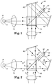
- FIGURE 1 is a schematic view of a projection system according to one embodiment of the present invention.
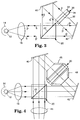
- FIGURE 2 is a schematic view of the projection system of FIGURE 1 when the pixels in the LCD are on.
- FIGURE 3 is a schematic view of the projection system of FIGURE 1 when the pixels in the LCD are off.
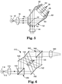
- FIGURE 4 is a schematic view of a projection system according to an alternative embodiment of the present invention which employs beam expanders.
- FIGURE 5 is a schematic view of a projection system according to a second alternative embodiment of the present invention which employs total internal reflection.
- FIGURE 6 is a schematic view of a projection system according to a third alternative embodiment of the present invention.
- a liquid crystal projection system 10 is shown in FIGURE 1.
- a light source 12 emits unpolarized light which is directed toward a collimating lens 16 with the help of a reflector 14. The light from light source 12 is then collimated by lens 16 and directed toward a polarizing beam splitter 20.
- Polarizing beam splitter reflects light of one polarization at face 22 while transmitting light having a polarization substantially orthogonal to the other polarization.
- the light which is reflected at face 22 of polarizing beam splitter 20 is directed toward a mirror 40, where it is reflected toward a liquid crystal display 30.
- Liquid crystal display 30 is comprised of transparent substrates 32 and 34 having an array of pixels 36 provided between them.
- the light beam passes through liquid crystal display 30 and on toward mirror 42, where it is reflected back toward polarizing beam splitter 20.
- Portions of the light beam are then either reflected at face 22 of beam splitter 20 or are transmitted through the beam splitter, depending on which pixels are on, off, or partially on, as will be explained later with reference to FIGURES 2 and 3.
- Portions of the light that are reflected will be directed toward a projection lens 44 for projection onto a viewing screen (not shown).
- Portions of the light that are transmitted will continue back toward lens 16, light source 12, and reflector 14, where they may be recycled back toward beam splitter 20 by the reflector, thereby increasing the brightness of an image formed on the viewing screen for a given power of the light source.
- the light which is not reflected at face 22 (which has a polarization substantially orthogonal to the beam that is reflected) is transmitted through beam splitter 20 toward mirror 42, where it is reflected toward liquid crystal display 30.
- the light beam then travels through liquid crystal display 30 and on toward mirror 40, where it is reflected back toward beam splitter 20.
- the light beam which is originally transmitted through polarizing beam splitter 20 passes through LCD 30 in the opposite direction as the light which is originally reflected at face 22 of the beam splitter.
- Portions of the light beam are then either transmitted through beam splitter 20 or reflected at face 22 of the beam splitter, depending on which pixels are on, off, or partially on. Portions that are transmitted will continue on to projection lens 44 for projection onto the viewing screen. Portions that are reflected will be directed toward lens 16, where they may be recycled back toward beam splitter 20 by reflector 14.
- LCD 30 should be positioned between mirrors 40 and 42 so that the optical path length between the LCD and projection lens 44 are equal regardless of whether the light rays pass through the LCD in one direction and are reflected by mirror 40 or pass through the LCD in the other direction and are reflected by mirror 42. This ensures that the images formed by both sets of light rays will be in focus on the viewing screen.
- LCD 30 is a TN type (direct, multiplex, or active matrix addressed).
- FIGURE 2 an electric field has been applied to pixels 36 of LCD 30, thereby turning the pixels "on". As explained earlier, when pixels 36 are in the "on” state, they do not affect the polarization state of light passing through them in either direction.
- Light emitted from light source 12 is unpolarized, and can therefore be said to be comprised of s-polarized light and p-polarized light.
- the polarization state of p-polarized light and s-polarized light is oriented orthogonally (90°) with respect to each other.
- s-polarized light has its polarization parallel to face 22 of polarizing beam splitter 20.
- Face 22 of polarizing beam splitter 20 is designed to reflect s-polarized light while transmitting p-polarized light.
- light from light source 12 is unpolarized and thus comprised of both s-polarized and p-polarized light.
- the s- and p-polarized light rays are shown in FIGURES 2 and 3 as separate rays for the purposes of illustration only.
- the s-polarized light is reflected at face 22 of beam splitter 20 and directed toward mirror 40, while the p-polarized light is transmitted through the beam splitter toward mirror 42.
- the s-polarized light is then reflected by mirror 40 toward LCD 30, while the p-polarized light is reflected by mirror 42 toward the opposite side of the LCD.
- pixels 36 When pixels 36 are in the "on" state, the polarization state of light passing through them in either direction is unaffected. Thus, the s-polarized light remains s-polarized as it passes through LCD 30, and the p-polarized light remains p-polarized as it passes through the LCD in the opposite direction.
- the s-polarized light is then reflected by mirror 42 back toward beam splitter 20, where it is reflected at face 22 toward projection lens 44 for viewing on a screen.
- the p-polarized light is then reflected by mirror 40 back toward beam splitter 20, where it is transmitted toward projection lens 40 for viewing on the screen.
- Beam splitter 20, mirrors 40 and 42, and LCD 30 must be properly oriented so that the s- and p- components of the light passing through a particular "on" pixel 36 are projected to the same position on the screen.
- FIGURE 3 no electric field has been applied to pixels 36 of LCD, thereby turning the pixels "off".
- pixels 36 when pixels 36 are in the "off" state, light passing through them in either direction is rotated by 90° so that its polarization angle is changed by 90°.
- p-polarized light becomes s-polarized, and vice versa.
- unpolarized light comprised of s-polarized light and p-polarized light, is emitted by light source 12.
- s-polarized light is reflected at face 22 of beam splitter 20 while the p-polarized light is transmitted through the beam splitter.
- the s-polarized light is reflected by mirror 40 toward LCD 30 while the p-polarized light is reflected by mirror 42 toward the opposite side of the LCD.
- the newly p-polarized light (formerly s-polarized) is then reflected by mirror 42 toward beam splitter 20. Because the light is now p-polarized, it passes through beam splitter 20 and back toward light source 12. Thus, the newly p-polarized light is not projected onto the screen, which is appropriate since pixels 36 are in the "off" state.
- the newly p-polarized light may, however, be reflected by reflector 14, or absorbed and re-emitted by light source 12, thereby recycling the unused p-polarized light, and thereby increasing the effective illumination power of the light source for any given power rating of the light source.
- the newly s-polarized light (formerly p-polarized) is then reflected by mirror 40 toward beam splitter 20. Because the light is now s-polarized, it is reflected at face 22 of beam splitter 20 back toward light source 12. Thus, the newly s-polarized light is not projected onto the screen, which is appropriate since the pixels 36 are in the "off" state.
- the newly s-polarized light is, however, reflected by reflector 14, thereby recycling the unused s-polarized light, and thereby increasing the effective illumination power of light source 12 for any given power rating of the light source.
- one advantage of the present invention is that s-polarized and p-polarized light which passes through "off" pixels, and therefore is not projected on the screen, is not merely wasted but is instead partially recycled within the projection system.
- projection system 10 is operating in the "normally black” (NB) mode, i.e., a particular pixel will be black if no voltage potential is applied across it.
- System 10 can be converted to the normally white (NW) mode by the insertion of a half-wave retarder.
- the retarder can preferably be placed on either side of LCD 30, or either of the sides of polarizing beam splitter 20 facing mirrors 40 and 42.
- the retarder should have its fast and slow axes at 45° to the s- and p-polarization directions.
- FIGURE 4 An alternative embodiment of the present invention is shown in FIGURE 4.
- the embodiment shown in FIGURE 4 differs from that of FIGURE 1 in that beam expanders 46 and 48 are provided on both sides of LCD 30. Beam expanders 46 and 48 may be provided adjacent LCD 30, as shown in FIGURE 4. In the alternative, the optical elements which comprise beam expanders 46 and 48 may be repositioned within the projection system as necessary. Beam expanders 46 and 48 allow the projection system to operate with an LCD which has a larger area than the cross-sectional area of the beam splitter. This allows for the use of a smaller beam splitter (e.g., about 5 cm along the diagonal) with a larger LCD (e.g., about 9 em along the diagonal).
- FIGURE 5 Another embodiment of the present invention is shown in FIGURE 5.
- the embodiment shown in FIGURE 5 differs from that of FIGURE 1 in that beam splitter 20 and mirrors 40 and 42 have been replaced with an optical element 50.
- Optical element 50 acts as a polarizing beam splitter (because of face 52) and also directs the polarized beams between the beam splitter face and LCD 30.
- Optical element 50 minimizes light loss within the projection system by the use of total internal reflection of the light within the optical element. The light is reflected to and from LCD 30 by sides 60, 61, 62, and 63 of optical element 50. Loss of light within the projection system can be minimized by providing anti-reflection coatings 54, 56, 64, and 66 on the surfaces of optical element 50 through which light enters.
- This embodiment is also advantageous in that the rigidity of optical element 50 avoids the potential for misalignment which may occur in the embodiment shown in FIGURE 1 where mirrors 40 and 42 are not rigidly fixed to polarizing beam splitter 20.
- This embodiment however, has the disadvantage of being heavier and costlier than the embodiment shown in FIGURE 1.
- FIGURES 1-5 are advantageous because they eliminate the need for providing separate polarizers on both sides of the LCDs.
- Such polarizers remove unwanted components of the source light, and therefore also reduce the amount of light passing through the LCD, thereby reducing the brightness of the projected image.
- These polarizers typically remove at least about one-half of the light incident on them.
- the use of the polarizing beam splitter in the present invention eliminates the need for the separate polarizers and allows both polarization components of the light to be used, instead of using only one and discarding the other. This nearly doubles the efficiency of the projection system, thereby doubling the brightness of the image formed by it.
- the approximately two-fold brightness improvement of the present invention is further enhanced by the recycling of unused light described earlier.
- Light which impinges an "off" pixel is eventually reflected back toward reflector 14, where it may be reflected back into projection system 10.
- the light might impinge an "on" pixel that is used to direct light onto the screen, thereby increasing the brightness of the screen image over that which would be present without the recycled light.
- this light originating only from the dark pixels of the image, is seldom considered a candidate for reuse in brightness enhancing techniques.
- the amount of the increase depends both on the geometry of the projection system and the content of the image or the LCD. Unlike other light recycling schemes in the prior art, this does not require the added expense of a quarter-wave retarder.
- Light source 12, reflector 14, and collimating lens 16 preferably provide collimated light.
- Preferred light sources include a metal halide high intensity discharge (HID) lamp or a tungsten halogen lamp.
- Polarizing beam splitter 20 is preferably a broad band cube having anti-reflection coatings on four of its faces, such as a one inch cube #BB1 available from Meadowlands Optics, Longmont, CO, or cube #10 FC16PB.3, available from Newport/Klinger, Irvine, CA, both of which cover the entire visible spectrum (400 nm to 700 nm).
- Mirrors 40 and 42 can be first surface metal mirrors, broad band dielectric mirrors, or any other type of mirror. Most pre-manufactured LCDs have polarizers provided on both of their sides. If such pre-manufactured LCDs are used, these polarizers must be removed.
- the LCD 30 has been described above as being a TN type, other types of LCDs can be used, such as ferroclectric (FE) LCDs, Super Twisted Nematic (STN) LCDs, or Triple Super Twisted Nematic (TSTN) LCDs.
- STN and TSTN LCDs may require the addition of a retardation plate.
- the brightness of the LCD may also be enhanced by providing microlens arrays on both sides of the LCD to increase the amount of light passing through the pixels, as is known in the art.
- FIGURE 6 Another embodiment of a liquid crystal projection system according to the present invention is shown as projection system 110 in FIGURE 6. In this embodiment, however, the unused light is not recycled back into the system.
- a light source 112 emits unpolarized light which is directed toward a collimating lens 116 with the help of reflector 114. The light from light source 112 is then collimated by lens 116 and directed toward a polarizing beam splitter 120.
- Polarizing beam splitter reflects light of one polarization at face 122 while transmitting light having a polarization substantially orthogonal to the other polarization.
- the light which is reflected at face 122 of polarizing beam splitter 120 is directed toward a mirror 140, where it is reflected toward a liquid crystal display 130.
- the light beam passes through liquid crystal display 130 and on toward mirror 152, where it is reflected toward a polarizing beam splitter 160.
- Portions of the light beam are then either reflected at face 162 of beam splitter 160 or are transmitted through the beam splitter, depending on which pixels are on, off, or partially on.
- the portions of the light that are reflected will be directed toward a projection lens 144 for projection onto a viewing screen (not shown).
- the light which is not reflected at face 122 (which has a polarization substantially orthogonal to the beam that is reflected) is transmitted through polarizing beam splitter 120 toward mirror 142, where it is reflected toward LCD 130.
- the light beam then travels through LCD 130 and on toward mirror 150, where it is reflected toward beam splitter 160.
- the light beam which is originally transmitted through polarizing beam splitter 120 passes through LCD 130 in the opposite direction as the light which is originally reflected at face 122 of the beam splitter.
- Portions of the light beam are then either transmitted through beam splitter 160 or reflected at face 162 of the beam splitter, depending on which pixels are on, off, or partially on. The portions of the light that are transmitted will continue on toward projection lens 144 for projection onto the viewing screen.
- LCD 30 can be provided with red, green, and blue (RGB) mosaic filters built within or atop the LCD.
- RGB red, green, and blue
- Another method of providing a color to the projected image is to use time-multiplexed color using a high speed black and white LCD.
- a revolving RGB filter wheel is provided in the optical path and the LCD is refreshed in synchrony with the position of the wheel.
- LCD 30 could also be comprised of a registered stack of three LCDs with intervening polarizers, each layer removing one of the yellow-magenta-cyan (YMC) primary colors.
- YMC yellow-magenta-cyan
- Another method of providing color is to split the original white light with a set of dichroic mirrors into three separate color beams, preferably red, green, and blue. These beams are then used to illuminate three separate LCDs which are modulated to give the respective color-separated images.
- a second set of dichroic mirrors recombines the red, green, and blue beams in imagewise registration for co-projection onto the screen.
- each LCD having a pair of reflecting mirrors positioned in a different plane.
- One dichroic mirror set lies between the polarizing beam splitter and one of the reflecting mirrors in each pair.
- the other dichroic mirror set lies between the polarizing beam splitter and the other of the reflecting mirrors in each pair.
- the components should be arranged so that the optical path lengths for each of the red, green, and blue beams from the polarizing beam splitter to the first set of dichroic mirrors, to one of the reflecting mirrors in each pair, through the LCD, to the other of the reflecting mirrors in each pair, and finally to the second set of dichroic mirrors, are equal.
- all three LCDs should be in the exact center of their respective optical paths described in the previous sentence.
- polarizing beam splitter 20 can be any means for splitting a beam into two beams having substantially orthogonal polarizations.
- the two light beams can be recombined by the same polarizing beam splitter or by a separate means for recombining the beams.
- the two polarizations have been described as linear polarizations, the invention can have utility with any two substantially orthogonal polarizations, such as right hand circularly polarized and left hand circularly polarized light.
- the display has been described as an LCD, the invention has utility with any polarization-modulating display.
Landscapes
- Chemical & Material Sciences (AREA)
- Crystallography & Structural Chemistry (AREA)
- Engineering & Computer Science (AREA)
- Multimedia (AREA)
- Signal Processing (AREA)
- Liquid Crystal (AREA)
- Projection Apparatus (AREA)
Applications Claiming Priority (2)
| Application Number | Priority Date | Filing Date | Title |
|---|---|---|---|
| US08/153,304 US5428469A (en) | 1993-11-16 | 1993-11-16 | Liquid crystal display projection systems employing polarizing beam splitters and passing light through display cell from both directions |
| US153304 | 1993-11-16 |
Publications (2)
| Publication Number | Publication Date |
|---|---|
| EP0653890A2 true EP0653890A2 (de) | 1995-05-17 |
| EP0653890A3 EP0653890A3 (de) | 1995-07-12 |
Family
ID=22546622
Family Applications (1)
| Application Number | Title | Priority Date | Filing Date |
|---|---|---|---|
| EP94117816A Withdrawn EP0653890A3 (de) | 1993-11-16 | 1994-11-11 | Flüssigkristallprojektionsanzeigevorrichtung. |
Country Status (3)
| Country | Link |
|---|---|
| US (1) | US5428469A (de) |
| EP (1) | EP0653890A3 (de) |
| JP (1) | JPH07191295A (de) |
Cited By (3)
| Publication number | Priority date | Publication date | Assignee | Title |
|---|---|---|---|---|
| EP0880725A4 (de) * | 1995-10-13 | 2000-01-05 | Unic View Ltd | Projektor |
| EP1744198A1 (de) * | 2005-07-16 | 2007-01-17 | Cairn Research Limited | Objektbeleuchtung mittels Raumlichtmodulatoren |
| CN100397908C (zh) * | 1997-08-20 | 2008-06-25 | 索尼公司 | 投影式显示装置 |
Families Citing this family (14)
| Publication number | Priority date | Publication date | Assignee | Title |
|---|---|---|---|---|
| US5729306A (en) * | 1994-09-30 | 1998-03-17 | Sharp Kabushiki Kaisha | Light splitting and synthesizing device and liquid crystal display apparatus including the same |
| US5995284A (en) * | 1996-03-29 | 1999-11-30 | 3M Innovative Properties Company | Polarized illumination system for LCD projector |
| US5940149A (en) * | 1997-12-11 | 1999-08-17 | Minnesota Mining And Manufacturing Company | Planar polarizer for LCD projectors |
| JP4040853B2 (ja) * | 2001-09-07 | 2008-01-30 | アルプス電気株式会社 | 照光装置 |
| SE524047C2 (sv) * | 2002-03-07 | 2004-06-22 | Flir Systems Ab | Förfarande och anordning för bi-monokulär bildöverföring |
| JP4216092B2 (ja) * | 2002-03-08 | 2009-01-28 | 株式会社半導体エネルギー研究所 | 液晶表示装置 |
| US7097315B2 (en) * | 2002-11-07 | 2006-08-29 | Microsensor Technology | Polarization conversion and recycling method and apparatus |
| JP3935139B2 (ja) * | 2002-11-29 | 2007-06-20 | 株式会社東芝 | 半導体記憶装置 |
| US7463417B2 (en) * | 2006-02-13 | 2008-12-09 | 3M Innovative Properties Company | Optical articles from curable compositions |
| US8422132B2 (en) * | 2008-12-02 | 2013-04-16 | Shanghai Lexvu Opto Microelectronics Technology Co., Ltd. | Integrated planar polarizing device |
| GB0907965D0 (en) * | 2009-05-08 | 2009-06-24 | King S College London | Imaging system |
| US9335555B1 (en) * | 2014-10-18 | 2016-05-10 | National Taiwan Normal University | Device for converting unpolarized incident light into polarized emitting light |
| DE102016211691B4 (de) | 2016-06-29 | 2024-04-25 | Volkswagen Aktiengesellschaft | Vorrichtung und Verfahren zum Erzeugen einer Ausgangslichtemission |
| CN107765495B (zh) * | 2016-08-18 | 2019-10-25 | 深圳光峰科技股份有限公司 | 一种显示系统 |
Family Cites Families (20)
| Publication number | Priority date | Publication date | Assignee | Title |
|---|---|---|---|---|
| US4090219A (en) * | 1974-12-09 | 1978-05-16 | Hughes Aircraft Company | Liquid crystal sequential color display |
| US4127322A (en) * | 1975-12-05 | 1978-11-28 | Hughes Aircraft Company | High brightness full color image light valve projection system |
| US4500172A (en) * | 1981-12-28 | 1985-02-19 | Hughes Aircraft Company | Two color liquid crystal light valve image projection system with single prepolarizer |
| US4850685A (en) * | 1984-10-22 | 1989-07-25 | Seiko Epson Corporation | Projection-type color display device |
| JPH061303B2 (ja) * | 1984-11-20 | 1994-01-05 | ソニー株式会社 | 偏光照明装置 |
| US4647966A (en) * | 1985-11-22 | 1987-03-03 | The United States Of America As Represented By The Secretary Of The Navy | Stereoscopic three dimensional large screen liquid crystal display |
| US4786146A (en) * | 1987-02-11 | 1988-11-22 | Hughes Aircraft Company | Color sequential illumination system for a liquid crystal light valve |
| US4826311A (en) * | 1987-07-24 | 1989-05-02 | Hughes Aircraft Company | Prism assembly with three periscopes and projection lenses for a single light valve full-color projector |
| US5300942A (en) * | 1987-12-31 | 1994-04-05 | Projectavision Incorporated | High efficiency light valve projection system with decreased perception of spaces between pixels and/or hines |
| NL8802104A (nl) * | 1988-08-26 | 1990-03-16 | Philips Nv | Beeldprojektie-inrichting. |
| US5235444A (en) * | 1988-08-26 | 1993-08-10 | U.S. Philips Corporation | Image projection arrangement |
| US5042921A (en) * | 1988-10-25 | 1991-08-27 | Casio Computer Co., Ltd. | Liquid crystal display apparatus |
| US4913529A (en) * | 1988-12-27 | 1990-04-03 | North American Philips Corp. | Illumination system for an LCD display system |
| FR2642927B1 (fr) * | 1989-02-07 | 1993-12-24 | Thomson Csf | Dispositif de visualisation a haute definition, couleur |
| JPH03163985A (ja) * | 1989-11-22 | 1991-07-15 | Pioneer Electron Corp | 液晶プロジェクタ |
| KR930003307B1 (ko) * | 1989-12-14 | 1993-04-24 | 주식회사 금성사 | 입체용 프로젝터 |
| US5115305A (en) * | 1990-07-05 | 1992-05-19 | Baur Thomas G | Electrically addressable liquid crystal projection system with high efficiency and light output |
| FR2665773B1 (fr) * | 1990-08-10 | 1993-08-20 | Thomson Csf | Dispositif de projection d'images utilisant deux composantes orthogonales de polarisation de la lumiere. |
| JPH04120586A (ja) * | 1990-09-11 | 1992-04-21 | Sharp Corp | 画像表示装置 |
| JPH04175744A (ja) * | 1990-11-08 | 1992-06-23 | Sharp Corp | 液晶プロジェクション装置 |
-
1993
- 1993-11-16 US US08/153,304 patent/US5428469A/en not_active Expired - Lifetime
-
1994
- 1994-11-11 EP EP94117816A patent/EP0653890A3/de not_active Withdrawn
- 1994-11-16 JP JP6281851A patent/JPH07191295A/ja active Pending
Cited By (4)
| Publication number | Priority date | Publication date | Assignee | Title |
|---|---|---|---|---|
| EP0880725A4 (de) * | 1995-10-13 | 2000-01-05 | Unic View Ltd | Projektor |
| CN100397908C (zh) * | 1997-08-20 | 2008-06-25 | 索尼公司 | 投影式显示装置 |
| EP1744198A1 (de) * | 2005-07-16 | 2007-01-17 | Cairn Research Limited | Objektbeleuchtung mittels Raumlichtmodulatoren |
| GB2428487B (en) * | 2005-07-16 | 2010-03-24 | Cairn Res Ltd | Illumination of objects using spatial light modulators |
Also Published As
| Publication number | Publication date |
|---|---|
| EP0653890A3 (de) | 1995-07-12 |
| JPH07191295A (ja) | 1995-07-28 |
| US5428469A (en) | 1995-06-27 |
Similar Documents
| Publication | Publication Date | Title |
|---|---|---|
| US4969730A (en) | Image projection arrangement | |
| KR100241641B1 (ko) | 이미지 투사 장치 | |
| US5428469A (en) | Liquid crystal display projection systems employing polarizing beam splitters and passing light through display cell from both directions | |
| US6490087B1 (en) | Optical systems for reflective LCD's | |
| US5621486A (en) | Efficient optical system for a high resolution projection display employing reflection light valves | |
| JP2765471B2 (ja) | 投写型液晶表示装置 | |
| JP4052282B2 (ja) | プロジェクタ | |
| KR100240909B1 (ko) | 이미지 투사 장치 | |
| US5726719A (en) | Projection-type color display device | |
| US5084807A (en) | Illumination system for LCD projection television | |
| KR20040042884A (ko) | 프로젝터 | |
| US6089718A (en) | Projection display device | |
| JP2004505300A (ja) | 等長の色成分光路を備えた電子投影機 | |
| US5235444A (en) | Image projection arrangement | |
| US5833338A (en) | Projector | |
| JPH10186548A (ja) | 投写型表示装置 | |
| EP0361559B1 (de) | Bildprojektionsvorrichtung | |
| JPH05100331A (ja) | 液晶表示装置 | |
| JPH10111539A (ja) | 投射型表示装置 | |
| JP3318760B2 (ja) | 表示装置 | |
| US20050213219A1 (en) | Means of compensation to increase the contrast ratio of LCoS based video projection systems | |
| JPH04127118A (ja) | 投写型表示装置 | |
| JPH06222303A (ja) | 投射型液晶表示装置 | |
| JPH0772497A (ja) | 画像投影装置 | |
| IL115638A (en) | Projector |
Legal Events
| Date | Code | Title | Description |
|---|---|---|---|
| PUAI | Public reference made under article 153(3) epc to a published international application that has entered the european phase |
Free format text: ORIGINAL CODE: 0009012 |
|
| AK | Designated contracting states |
Kind code of ref document: A2 Designated state(s): DE ES FR GB IT NL |
|
| PUAL | Search report despatched |
Free format text: ORIGINAL CODE: 0009013 |
|
| AK | Designated contracting states |
Kind code of ref document: A3 Designated state(s): DE ES FR GB IT NL |
|
| 17P | Request for examination filed |
Effective date: 19951213 |
|
| 17Q | First examination report despatched |
Effective date: 19971215 |
|
| STAA | Information on the status of an ep patent application or granted ep patent |
Free format text: STATUS: THE APPLICATION IS DEEMED TO BE WITHDRAWN |
|
| 18D | Application deemed to be withdrawn |
Effective date: 19980428 |