EP0654593B1 - Zündzeitsteuerungsystem für Brennkraftmaschinen - Google Patents
Zündzeitsteuerungsystem für Brennkraftmaschinen Download PDFInfo
- Publication number
- EP0654593B1 EP0654593B1 EP94118430A EP94118430A EP0654593B1 EP 0654593 B1 EP0654593 B1 EP 0654593B1 EP 94118430 A EP94118430 A EP 94118430A EP 94118430 A EP94118430 A EP 94118430A EP 0654593 B1 EP0654593 B1 EP 0654593B1
- Authority
- EP
- European Patent Office
- Prior art keywords
- engine
- fuel
- ignition timing
- amount
- control system
- Prior art date
- Legal status (The legal status is an assumption and is not a legal conclusion. Google has not performed a legal analysis and makes no representation as to the accuracy of the status listed.)
- Expired - Lifetime
Links
Images


Classifications
-
- F—MECHANICAL ENGINEERING; LIGHTING; HEATING; WEAPONS; BLASTING
- F02—COMBUSTION ENGINES; HOT-GAS OR COMBUSTION-PRODUCT ENGINE PLANTS
- F02P—IGNITION, OTHER THAN COMPRESSION IGNITION, FOR INTERNAL-COMBUSTION ENGINES; TESTING OF IGNITION TIMING IN COMPRESSION-IGNITION ENGINES
- F02P5/00—Advancing or retarding ignition; Control therefor
- F02P5/04—Advancing or retarding ignition; Control therefor automatically, as a function of the working conditions of the engine or vehicle or of the atmospheric conditions
- F02P5/145—Advancing or retarding ignition; Control therefor automatically, as a function of the working conditions of the engine or vehicle or of the atmospheric conditions using electrical means
- F02P5/15—Digital data processing
- F02P5/1502—Digital data processing using one central computing unit
- F02P5/1504—Digital data processing using one central computing unit with particular means during a transient phase, e.g. acceleration, deceleration, gear change
-
- F—MECHANICAL ENGINEERING; LIGHTING; HEATING; WEAPONS; BLASTING
- F02—COMBUSTION ENGINES; HOT-GAS OR COMBUSTION-PRODUCT ENGINE PLANTS
- F02D—CONTROLLING COMBUSTION ENGINES
- F02D37/00—Non-electrical conjoint control of two or more functions of engines, not otherwise provided for
- F02D37/02—Non-electrical conjoint control of two or more functions of engines, not otherwise provided for one of the functions being ignition
-
- F—MECHANICAL ENGINEERING; LIGHTING; HEATING; WEAPONS; BLASTING
- F02—COMBUSTION ENGINES; HOT-GAS OR COMBUSTION-PRODUCT ENGINE PLANTS
- F02D—CONTROLLING COMBUSTION ENGINES
- F02D41/00—Electrical control of supply of combustible mixture or its constituents
- F02D41/02—Circuit arrangements for generating control signals
- F02D41/04—Introducing corrections for particular operating conditions
- F02D41/047—Taking into account fuel evaporation or wall wetting
-
- F—MECHANICAL ENGINEERING; LIGHTING; HEATING; WEAPONS; BLASTING
- F02—COMBUSTION ENGINES; HOT-GAS OR COMBUSTION-PRODUCT ENGINE PLANTS
- F02D—CONTROLLING COMBUSTION ENGINES
- F02D41/00—Electrical control of supply of combustible mixture or its constituents
- F02D41/02—Circuit arrangements for generating control signals
- F02D41/04—Introducing corrections for particular operating conditions
- F02D41/12—Introducing corrections for particular operating conditions for deceleration
- F02D41/123—Introducing corrections for particular operating conditions for deceleration the fuel injection being cut-off
- F02D41/126—Introducing corrections for particular operating conditions for deceleration the fuel injection being cut-off transitional corrections at the end of the cut-off period
-
- F—MECHANICAL ENGINEERING; LIGHTING; HEATING; WEAPONS; BLASTING
- F02—COMBUSTION ENGINES; HOT-GAS OR COMBUSTION-PRODUCT ENGINE PLANTS
- F02B—INTERNAL-COMBUSTION PISTON ENGINES; COMBUSTION ENGINES IN GENERAL
- F02B2275/00—Other engines, components or details, not provided for in other groups of this subclass
- F02B2275/18—DOHC [Double overhead camshaft]
-
- Y—GENERAL TAGGING OF NEW TECHNOLOGICAL DEVELOPMENTS; GENERAL TAGGING OF CROSS-SECTIONAL TECHNOLOGIES SPANNING OVER SEVERAL SECTIONS OF THE IPC; TECHNICAL SUBJECTS COVERED BY FORMER USPC CROSS-REFERENCE ART COLLECTIONS [XRACs] AND DIGESTS
- Y02—TECHNOLOGIES OR APPLICATIONS FOR MITIGATION OR ADAPTATION AGAINST CLIMATE CHANGE
- Y02T—CLIMATE CHANGE MITIGATION TECHNOLOGIES RELATED TO TRANSPORTATION
- Y02T10/00—Road transport of goods or passengers
- Y02T10/10—Internal combustion engine [ICE] based vehicles
- Y02T10/40—Engine management systems
Definitions
- This invention relates to an ignition timing control system for internal combustion engines, and more particularly to an ignition timing control system for an internal combustion engine equipped with a fuel injection amount control system which calculates a fuel injection amount so as to compensate for an amount of fuel (liquid fuel) adhering to the inner wall surface of the intake pipe of the engine after being injected into the intake pipe.
- a fuel supply amount control method for internal combustion engines which eliminates the above inconvenience, has been known, for example, from Japanese Patent Publication (Kokoku) No.
- the above-mentioned proposed method has eliminated a drawback of a conventional fuel injection amount control method which is based on the premise that injected fuel is drawn in a sufficient amount into the combustion chamber of the engine, more specifically, a drawback that an insufficient amount of fuel is supplied to the engine due to a larger amount of fuel adhering to the inner surface of the intake pipe immediately after fuel cut, i.e. interruption of fuel supply to the engine has been completed.
- the proposed fuel supply amount control method which controls the fuel injection amount to be supplied to the engine in a manner compensating for the adherent fuel amount and the carried-off fuel amount, when the engine is recovered from a fuel-cut state into a fuel supply state (hereinafter referred to as "the recovery from F/C"), the following inconvenience arises:
- the adherent fuel amount is regarded as "0". Accordingly, at the recovery from F/C, a value of adherent fuel amount x carry-off ratio (ratio of an amount of fuel drawn into the combustion chamber of the engine during the present cycle to an amount of fuel having stayed in the intake pipe up to the immediately preceding cycle) becomes "0", and hence a larger amount of fuel than an amount actually required by the engine is injected, which includes an amount of fuel newly adhering to the wall surface of the intake pipe. As a result, no lean spike occurs, so that the fluctuation of the engine torque is not reduced at the recovery from F/C, and hence the engine undergoes a shock which is not suppressed.
- US-A-4543634 provides a system for preventing after-burns following abrupt closure of a throttle valve to obviate increased heat loss and possible engine overheating. This is done by controlling the ignition timing to an optimal value when a throttle closed signal is not output, controlling ignition timing for a maximum fixed ignition advance angle when the throttle closed signal is output and, upon resumption of fuel injection, progressively returning the ignition timing to the optimum ignition advanced angle at a rate commensurate with the engine rotational speed.
- EP-A 295650 discloses an air-to-fuel ratio control apparatus suitable for gasoline engine in automobiles. This document concerns compensation for air-to-fuel ratios with sufficiently high precision even immediately following a change into a transient driving stage. This is done by providing means for determining the adhesion rate of fuel and the time constant of evaporation of the fuel in a fuel injection and suction system and by determining the amount of fuel to be supplied on the basis of the adhesion rate, the time constant of evaporation and the condition of the engine.
- the present invention provide an ignition timing control system according to claim 1.
- the adherent amount of fuel adhering to the inner wall surface of the intake passage, and the carried-off amount of fuel to be carried off from the adherent fuel into each of the at least one combustion chamber of the engine are calculated based on operating conditions of the engine detected by the engine operating condition-detecting means.
- the retard amount-calculating means calculates the retard amount, based on the pressure within the intake passage detected by the engine operating condition-detecting means.
- the retard amount-calculating means calculates the retard amount, based on the pressure within the intake passage and a rotational speed of the engine detected by the engine operating condition-detecting means.
- the ignition timing control system includes retard amount-decrementing means for sequentially decrementing the retard amount.
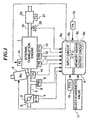
- Fig. 1 there is illustrated the whole arrangement of an internal combustion engine and an ignition timing control system therefor, according to an embodiment of the invention.
- reference numeral 1 designates a DOHC straight type four-cylinder engine (hereinafter simply referred to as “the engine”), each cylinder being provided with a pair of intake valves, not shown, and a pair of exhaust valves, not shown.
- This engine is constructed such that it is capable of changing operating characteristics of the intake valves and exhaust valves, for example, the valve opening period and the valve lift (generically referred to hereinafter as “the valve timing") between a high speed valve timing (hereinafter referred to as “the high speed V/T”) adapted for engine operation in a high engine speed region and a low speed valve timing (hereinafter referred to as "the low speed V/T”) adapted for engine operation in a low engine speed region.
- the high speed V/T high speed valve timing
- the low speed V/T low speed valve timing
- an intake pipe 2 Connected to an intake port, not shown, of the cylinder block of the engine 1 is an intake pipe 2 across which is arranged a throttle body 3 accommodating a throttle valve 3' therein.
- a throttle valve opening ( ⁇ TH) sensor 4 is connected to the throttle valve 3' for generating an electric signal indicative of the sensed throttle valve opening ⁇ TH and supplying same to an electric control unit (hereinafter referred to as "the ECU") 5.
- Fuel injection valves (INJ) 6, only one of which is shown, are inserted into the intake pipe 2 at locations intermediate between the cylinder block of the engine 1 and the throttle valve 3' and slightly upstream of respective intake valves, not shown.
- the fuel injection valves 6 are connected to a fuel pump, not shown, via a fuel supply pipe 7 and electrically connected to the ECU 5 to have their valve opening periods controlled by signals therefrom.
- an intake pipe absolute pressure (PBA) sensor 9 is provided in communication with the interior of the intake pipe 2 via a conduit 8 opening into the intake pipe 2 at a location between the throttle valve 3' and the fuel injection valves 6, for supplying an electric signal indicative of the sensed absolute pressure PBA within the intake pipe 2 to the ECU 5.
- PBA intake pipe absolute pressure
- An intake air temperature (TA) sensor 10 is inserted into the intake pipe 2 at a location downstream of the conduit 8, for supplying an electric signal indicative of the sensed intake air temperature TA to the ECU 5.
- An engine coolant temperature (TW) sensor 11 formed of a thermistor or the like is inserted into a coolant passage filled with a coolant and formed in the cylinder block, for supplying an electric signal indicative of the sensed engine coolant temperature TW to the ECU 5.
- a crank angle (CRK) sensor 12 and a cylinder-discriminating (CYL) sensor 13 are arranged in facing relation to a camshaft or a crankshaft of the engine 1, neither of which is shown.
- the CRK sensor 12 generates a CRK signal pulse whenever the crankshaft rotates through a predetermined angle (e.g. 30 degrees) smaller than half a rotation (180 degrees) of the crankshaft of the engine 1, while the CYL sensor 13 generates a pulse (hereinafter referred to as "the CYL signal pulse") at a predetermined crank angle of a particular cylinder of the engine, both of the CRK signal pulse and the CYL signal pulse being supplied to the ECU 5.
- a predetermined angle e.g. 30 degrees
- the CYL signal pulse a pulse at a predetermined crank angle of a particular cylinder of the engine
- Each cylinder of the engine has a spark plug (IG) 15 electrically connected to the ECU 5 to have its ignition timing controlled by a signal therefrom. Further, an atmospheric pressure (PA) sensor 16 is arranged at a suitable location of the engine 1 for supplying an electric signal indicative of the sensed atmospheric pressure PA to the ECU 5.
- IG spark plug
- PA atmospheric pressure
- an electromagnetic valve 17 for making changeover of the valve timing, which has opening and closing operations thereof controlled by a signal from the ECU 5.
- the electromagnetic valve 17 selects either high or low hydraulic pressure applied to a valve timing changeover device, not shown. Responsive to this high or low hydraulic pressure selected, the valve timing changeover device operates to change the valve timing to either the high speed V/T or the low speed V/T.
- the hydraulic pressure applied to the valve timing changeover device is detected by a hydraulic pressure (oil pressure) (Poil) sensor 18 which supplies an electric signal indicative of the sensed hydraulic pressure POIL to the ECU 5.
- a catalytic converter (three-way catalyst) 20 is arranged in an exhaust pipe 19 connected to an exhaust port, not shown, of the engine 1, for purifying noxious components, such as HC, CO, NOx, which are present in exhaust gases.
- a catalyst temperature (TC) sensor 21 which is formed of a thermistor or the like, is inserted into a housing wall of the catalytic converter 20, for supplying an electric signal indicative of the sensed temperature TC of the catalytic converter 20 to the ECU 5.
- a linear output type air-fuel ratio sensor (hereinafter referred to as "the LAF sensor") 22 is arranged in the exhaust pipe 19 at a location upstream of the catalytic converter 20.
- the LAF sensor 22 supplies an electric signal which is substantially proportional to the concentration of oxygen present in exhaust gases to the ECU 5.
- the ECU 5 is comprised of an input circuit 5a having the functions of shaping the waveforms of input signals from various sensors as mentioned above, shifting the voltage levels of sensor output signals to a predetermined level, converting analog signals from analog-output sensors to digital signals, and so forth, a central processing unit (hereinafter referred to as the "the CPU") 5b, memory means 5c formed of a ROM (read only memory) storing various operational programs which are executed by the CPU 5b, and various maps and tables, referred to hereinafter, and a RAM (random access memory) for storing results of calculations therefrom, etc., the aforementioned output circuit 5d which outputs driving signals to the fuel injection valves 6, the spark plugs 15, the fuel pump, the electromagnetic valve 17, etc.
- the CPU central processing unit
- memory means 5c formed of a ROM (read only memory) storing various operational programs which are executed by the CPU 5b, and various maps and tables, referred to hereinafter, and a RAM (random access memory) for storing results of calculations therefrom
- Fig. 2 shows a timing chart showing the relationship in timing between CRK signal pulses from the CRK sensor 12, CYL signal pulses from the CYL sensor 13, TDC-discriminating signal pulses from the ECU 5, and injection timing of fuel by the fuel injection valves 6.
- Twenty-four CRK signal pulses are generated per two rotations of the crankshaft at regular intervals with respect to the top dead center position of each of the four cylinders (#1 to #4 CYL), i.e. one CRK signal pulse whenever the crankshaft rotates through 30 degrees.
- the ECU 5 generates a TDC-discriminating signal pulse in synchronism with a CRK signal pulse generated at the top dead center position of each cylinder.
- the TDC-discriminating signal pulses indicate reference crank angle positions of the respective cylinders and are each generated whenever the crankshaft rotates through 180 degrees.
- the ECU 5 measures time intervals of generation of the CRK signal pulses to calculate CRME values, which are added together over a time period of generation of two TDC-discriminating signal pulses i.e. over a time period of one rotation of the crankshaft to calculate an ME value, and then calculates the engine rotational speed NE, which is the reciprocal of the ME value, based on the ME value.
- CYL signal pulses are each generated as briefly described above, at a predetermined crank angle position of a particular cylinder (cylinder #1 in the illustrated example), e.g. when the #1 cylinder is in a position 90 degrees before a TDC position thereof corresponding to the end of the compression stroke of the cylinder, to thereby allot a particular cylinder number (e.g. #1 CYL) to a TDC-discriminating signal pulse generated immediately after a CYL signal pulse is generated.
- a particular cylinder number e.g. #1 CYL
- the ECU 5 detects crank angle stages (hereinafter referred to as "the stages") in relation to the reference crank angle position of each cylinder, based on the TDC-discriminating signal pulses and the CRK signal pulses. More specifically, the ECU 5 determines, for instance, that the #1 cylinder is in a #0 stage when a CRK signal pulse is generated, which corresponds to a TDC-discriminating signal pulse generated at the end of compression stroke of the #1 cylinder immediately following a CYL signal pulse. The ECU sequentially determines thereafter that the #1 cylinder is in a #1 stage, in a #2 stage, ....and in a # 23 stage, based on CRK signal pulses generated thereafter.
- the stages crank angle stages
- an injection stage of a cylinder at which injection should be started is set depending on operating conditions of the engine 1, more particularly by executing an injection stage-determining routine, not shown. Further, the valve opening period (fuel injection period TOUT) of each fuel injection valve 6 is controlled by the use of a status number (SINJ(k)) determined in relation to the injection stage.
- the status number SINJ(k) is set to "2" during the valve opening period of the fuel injection valve 6, and changed to "3" immediately upon termination of injection.
- the status number SINJ(k) is reset to "0" simultaneously when the explosion stroke starts, to set the next fuel injection valve 6 into a standby state for injection. Thereafter, when the cylinder reaches the next injection stage (e.g. the #13 stage), the status number SINJ(k) is set to "1", and after a predetermined injection delay time period elapses, the status number SINJ(k) is again set to "2" to start fuel injection via the next fuel injection valve 6. Immediately upon termination of the fuel injection, the status number SINJ(k) is again set to "3", and upon start of the explosion stroke, it is again reset to "0".
- the injection delay time period (corresponding to the time period over which the status number SINJ(k) is equal to "1") is provided for controlling the injection timing such that the fuel injection is completed at desired injection termination timing.
- a required amount of fuel which is required by the engine i.e. which should be supplied to the combustion chamber is calculated based on operating conditions of the engine 1 including the intake pipe absolute pressure PBA and the engine rotational speed NE. Then, a final fuel injection amount to be injected by the fuel injection valve 6 is determined with the adherent fuel amount TWP adhering to the wall surface of the intake pipe 2 taken into account.
- the ignition timing of the spark plug 15 is controlled based on operating conditions of the engine 1, and at the recovery from F/C, a retard value of the injection timing and a predetermined number of TDC pulses are determined based on the intake pipe absolute pressure PBA.
- Fig. 3 shows a routine for carrying out an adherent fuel-dependent correction, which is executed in synchronism with generation of each TDC-discriminating signal pulse.
- Fig. 4 shows details of the LPARA-determining routine for determining the above-mentioned adherent fuel-determining parameters, which is executed in synchronism with generation of each TDC-discriminating signal pulse.
- a basic direct supply ratio A is determined by retrieving an A map.
- the A map is set, e.g. as shown in Fig. 5, such that map values A(0,0) to A(6,6) are provided in a manner corresponding to predetermined values PBA0 to PBA6 of the intake pipe absolute pressure PBA and predetermined values TW0 to TW6 of the engine coolant temperature TW.
- the basic direct supply ratio A is determined by being read from the A map, and additionally by interpolation, if required.
- a basic carry-off ratio B is determined by retrieving a B map.
- the B map is set similarly to the A map, e.g. as shown in Fig. 6, such that map values B(0,0) to B(6,6) are provided in a manner corresponding to the predetermined values PBA0 to PBA6 of the intake pipe absolute pressure PBA and the predetermined values TW0 to TW6 of the engine coolant temperature TW.
- the basic carry-off ratio B is determined by being read from the B map, and additionally by interpolation, if required.
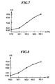
- an engine speed-dependent correction coefficient KA for the final direct supply Ae is determined by retrieving a KA table.
- the KA table is set, e.g. as shown in Fig. 7, such that table values KA0 to KA4 are provided in a manner corresponding to predetermined values NE0 to NE4 of the engine rotational speed NE.
- the engine speed-dependent correction coefficient KA is determined by being read from the KA table, and additionally by interpolation, if required.
- an engine speed-dependent correction coefficient KB for the final carry-off ratio Be is determined by retrieving a KB table.
- the KB table is set similarly to the KA table, e.g. as shown in Fig. 8, such that table values KB0 to KB4 are provided in a manner corresponding to the predetermined values NE0 to NE4 of the engine rotational speed NE.
- the engine speed-dependent correction coefficient KB is determined by being read from the KB table, and additionally by interpolation, if required.
- step S303 an HPARA-determining routine, not shown, is executed to determine adherent fuel-determining parameters suitable for the high speed V/T, i.e. a final direct supply ratio Ae and a final carry-off ratio Be of gasoline as injected fuel for use in fuel injection control during the high speed V/T in a similar manner to the LPAKA-determining routine.
- K1 and K2 represent other correction coefficients and correction variables, respectively, which are set depending on operating conditions of the engine to such values as optimize operating characteristics of the engine, such as the fuel consumption and the accelerability.
- steps S306 et seq. are executed for each of the cylinders (#1CYL to #4CYL).
- a TiM map, not shown, is used for determining the TiM value.
- KTOTAl represents the sum of all correction coefficients which are determined based on engine operating parameter signals from various sensors.
- TTOTAL represents the sum of all addend correction variables (e.g. atmospheric pressure-dependent correction variable TPA) which are determined based on engine operating parameter signals from various sensors.
- TPA atmospheric pressure-dependent correction variable
- a correction term TV for a so-called ineffective time period elapsed before the fuel injection valve 6 opens is not included in the TTOTAL value.
- TWP(k) represents an estimated amount of fuel adhering to the inner wall surface of the intake pipe 2, which is calculated according to a routine described hereinafter with reference to Fig. 9, and hence the term (Be x TWP(k)) represents a fuel amount carried off the adherent fuel into the combustion chamber. This carried-off amount from the adherent fuel need not be newly supplied by injection, and hence is subtracted from the required fuel amount TREQ(k) according to the equation (4).
- a step S307 it is determined whether or not the desired fuel injection period TNET(k) calculated as above is equal to or smaller than "0". If TNET ⁇ 0, a final fuel injection period TOUT(k) is set to "0" to forcibly interrupt the fuel supply at a step S308, followed by terminating the program.
- TOUT(k) TNET(k)/Ae x KLAF + TV
- KLAF represents an air-fuel ratio correction coefficient determined based on an output from the LAF sensor 22, and TV the aforementioned correction term for the ineffective time period of the fuel injection valve 6.
- the fuel injection period is calculated for the #1 cylinder, and then the steps S306 to S309 in Fig. 3 are repeatedly carried out similarly, to determine the final fuel injection period TOUT for the #2 cylinder to #4 cylinder as well.
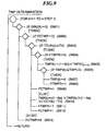
- Fig. 9 shows a TWP-determining routine for determining the adherent fuel amount TWP, which is executed for each cylinder whenever the crankshaft rotates through a predetermined angle (e.g. 30 degrees).
- step S901 it is determined at a step S901 whether or not the status number SINJ(k) (see Fig. 2) is equal to "3", which indicates termination of fuel injection. If SINJ(k) is not equal to "3", the program proceeds to a step S913, wherein a calculation-permitting flag FCTWP is set to "0" to allow the calculation of the adherent fuel amount TWP to be started in the next or a subsequent loop.
- step S902 determines whether or not the flag FCTWP is equal to "0". If FCTWP is equal to "0”, it is determined at a step S903 whether or not the final fuel injection period TOUT(k) is smaller than the ineffective time period TV. If TOUT(k) ⁇ TV, which means that no fuel is to be injected, such as during a fuel cut state of the engine, it is determined at a . step S904 whether or not a flag FTWPR is equal to "0", i.e. whether or not the adherent fuel amount TWP is negligible or zero.
- step S906 it is determined at a step S906 whether or not the adherent fuel amount TWP(k) is equal to or smaller than a predetermined very small value TWPLG. If TWP(k) ⁇ TWPLG, it is judged that the adherent fuel amount TWP(k) is negligible or zero. Then, at a step S907, the adherent fuel amount TWP(k) is set to "0", and the flag FTWPR is set to "1" at a step S908.
- the flag FCTWP is set to "1" to indicate completion of the calculation of the adherent fuel amount TWP, followed by terminating the program.
- TWP(k) (1 - Be) x TWP(k)(n-1) + (1 - Ae) x (TOUT(k) - TV) where TWP(k)(n-1) represents an immediately preceding value of the adherent fuel amount TWP(k).
- the first term on the right side represents an amount of fuel which has not been carried off from the adherent fuel and remains on the inner wall surface of the intake pipe 2 during the present cycle
- the second term on the right side represents an amount of fuel corresponding to a portion of fuel injected in the present loop which has not been drawn into the combustion chamber and newly adhered to the inner wall surface of the intake pipe 2.
- the flag FTWPR is set to "1" at a step S911 to indicate that the adherent fuel amount TWP is present, and further the flag FCTWP is set to "1" at a step S912 to indicate completion of the calculation of the adherent fuel amount TWP, followed by terminating the program.
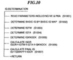
- Fig. 10 shows an air-fuel ratio feedback control routine expressed according to the SPD, which is executed in synchronism with generation of each TDC-discriminating signal pulse.
- step S1001 various engine operating parameters including the engine rotational speed NE and the intake pipe absolute pressure PBA, etc. are read.
- step S1002 a basic ignition timing map is retrieved based on the read engine rotational speed NE and intake pipe absolute pressure PBA, to thereby determine a value of basic ignition timing IGMAP.
- the basic ignition timing map is set such that map values are provided in a manner corresponding to predetermined values of the engine rotational speed NE and predetermined values of the intake pipe absolute pressure PBA.
- the basic ignition timing IGMAP is determined by being read from the basic ignition timing map, and additionally by interpolation, if required.
- an engine coolant-dependent correction coefficient IGTW is determined at a step S1003, an intake air temperature-dependent correction coefficient IGTA at a step S1004, and a knocking correction coefficient IGKNOCK at a step S1005, respectively.
- These correction coefficients are determined by retrieving respective corresponding maps.
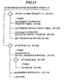
- a flag FFC is set to "0" and at the same time a flag FFCLAST is set to "1", i.e. whether or not the engine has been recovered from a fuel cut state.
- the flag FFC is set to "1” and “0”, respectively, when the engine is in a fuel cut state and in a non-fuel cut state in the present loop, and the flag FFCLAST is to "1" and "0", respectively, when the engine was in a fuel cut state and in a non-fuel cut state in the last loop.
- the determination as to whether the engine is in a fuel cut state is executed, e.g.
- a TDCAFC table is retrieved to determine a value TDCAFCN which indicates a predetermined number of TDC-discriminating signal pulses, (e.g. 16) for determining a retard amount for the ignition time after the recovery from F/C, based on the intake pipe absolute pressure PBA.
- the TDCAFCN value i.e. the number of TDC-discriminating signal pulses after the recovery from F/C, which has been calculated at the step S1102, is set as a value AFRTDC.
- the IG value calculated by the equation (11) is applied as the ignition timing per TDC position of the engine after recovery from F/C whenever a TDC-discriminating signal pulse is generated.
- a limit value IGLimit of the calculated IG value is provided in view of the possibility that the IGRTD value assumes too large a value. That is, at a step S1108, limit checking is executed by determining whether or not the calculated theoretical ignition timing IG is equal to or smaller than the limit value IGLimit. If the theoretical ignition timing IG is equal to or smaller than the limit value IGLimit, the program proceeds to a step S1109, wherein the theoretical ignition timing IG is set to the limit value IGLimit. Then, at a step S1110, the AFRTDC value is decremented by "1", followed by completing the present routine.
- the retard value IGRTD of the ignition timing and the predetermined number TDCAFCN of TDC-discriminating signal pulses are determined based on the intake pipe absolute pressure PBA, they may be determined based on the intake pipe absolute pressure PBA and the engine rotational speed NE.
Landscapes
- Engineering & Computer Science (AREA)
- Chemical & Material Sciences (AREA)
- Combustion & Propulsion (AREA)
- Mechanical Engineering (AREA)
- General Engineering & Computer Science (AREA)
- Theoretical Computer Science (AREA)
- Signal Processing (AREA)
- Electrical Control Of Air Or Fuel Supplied To Internal-Combustion Engine (AREA)
- Combined Controls Of Internal Combustion Engines (AREA)
- Electrical Control Of Ignition Timing (AREA)
Claims (5)
- Zündzeitsteuerungssystem für eine Brennkraftmaschine (1) mit einer Einlasspassage (2), die eine Innenwandfläche aufweist, und mindestens einer Verbrennungskammer, wobei das Zündzeitsteuerungssystem mit einem Kraftstoffeinspritzmengensteuerungssystem zum Berechnen einer der Maschine zuzuführenden Kraftstoffmenge auf der Basis von Betriebsbedingungen der Maschine verbunden ist, das die berechnete Kraftstoffmenge auf der Basis einer haftenden Kraftstoffmenge korrigiert, die an der Innenwandfläche der Einlasspassage (2) haftet, und einer abgetragenen Kraftstoffmenge, die vom haftenden Kraftstoff in jede der mindestens einen Verbrennungskammer der Maschine (1) abgetragen werden soll, und das die korrigierte Kraftstoffmenge in die Einlasspassage (2) einspritzt, wobei das Zündzeitsteuerungssystem umfasst:dadurch gekennzeichnet, dass das System zusätzlich eine Zündzeit-Begrenzungseinrichtung (5) zum Setzen der von der Zündzeit-Korrektureinrichtung korrigierten Zündzeit auf einen vorbestimmten Wert aufweist, wenn die Zündzeit kleiner als der vorbestimmte Wert ist.eine Maschinenbetriebsbedingung-Detektiereinrichtung (9, 10, 11, 12, 13, 16) zum Detektieren von Betriebsbedingungen der Maschine (1) einschließlich zumindest des Drucks innerhalb der Einlasspassage (2);eine Kraftstoffzufuhrrückkehr-Detektiereinrichtung (5, 12, 13) zum Detektieren, ob die Maschine von einem kraftstoffabgeschnittenen Zustand, wo die Kraftstoffzufuhr zur Maschine unterbrochen ist, zu einem Kraftstoffzufuhrzustand, wo der Maschine der Kraftstoff zugeführt wird, zurückgekehrt ist;eine Zündzeit-Berechnungseinrichtung (5) zum Berechnen der Zündzeit auf der Basis von Betriebsbedingungen der Maschine, die von der Maschinenbetriebsbedingung-Detektiereinrichtung detektiert werden;eine Verzögerungsmenge-Berechnungseinrichtung (5) zum Berechnen einer Verzögerungsmenge, durch welche die Zündzeit der Maschine verzögert werden soll, auf der Basis von Betriebsbedingungen der Maschine, die von der Maschinenbetriebsbedingung-Detektiereinrichtung detektiert werden, wenn von der Kraftstoffrückkehr-Detektiereinrichtung detektiert wird, dass die Maschine vom kraftstoffabgeschnittenen Zustand zum Kraftstoffzufuhrzustand zurückgekehrt ist; undeine Zündzeit-Korrektureinrichtung (5) zum Korrigieren der zu verzögernden Zündzeit um die Verzögerungsmenge, die von der Verzögerungsmenge-Berechnungseinrichtung berechnet wird, wenn von der Kraftstoffrückkehr-Detektiereinrichtung detektiert wird, dass die Maschine vom kraftstoffabgeschnittenen Zustand zum Kraftstoffzufuhrzustand zurückgekehrt ist,
- Zündzeitsteuerungssystem nach Anspruch 1, wobei die haftende Kraftstoffmenge, die an der Innenwandfläche der Einlasspassage (2) haftet, und die abgetragene Kraftstoffmenge, die vom haftenden Kraftstoff in jede der mindestens einen Verbrennungskammer der Maschine (1) abgetragen werden soll, berechnet werden auf der Basis von Betriebsbedingungen der Maschine, die von der Maschinenbetriebsbedingung-Detektiereinrichtung (9, 10, 11, 12, 13, 16) detektiert werden.
- Zündzeitsteuerungssystem nach Anspruch 1, wobei die Verzögerungsmenge-Berechnungseinrichtung (5) die Verzögerungsmenge auf der Basis des Drucks innerhalb der Einlasspassage (2) berechnet, der von der Maschinenbetriebsbedingung-Detektiereinrichtung (9) detektiert wird.
- Zündzeitsteuerungssystem nach Anspruch 1 wobei die Verzögerungsmenge-Berechnungseinrichtung (5) die Verzögerungsmenge auf der Basis des Drucks innerhalb der Einlasspassage (2) und einer Drehzahl der Maschine (1) berechnet, die von der Maschinenbetriebsbedingung-Detektiereinrichtung (12, 13) detektiert werden.
- Zündzeitsteuerungssystem nach einem der vorhergehenden Ansprüche, das eine Verzögerungsmenge-Verringerungseinrichtung (5) zum sequentiellen Verringern der Verzögerungsmenge einschließt.
Applications Claiming Priority (3)
| Application Number | Priority Date | Filing Date | Title |
|---|---|---|---|
| JP317388/93 | 1993-11-24 | ||
| JP31738893 | 1993-11-24 | ||
| JP5317388A JPH07145771A (ja) | 1993-11-24 | 1993-11-24 | 内燃機関の点火時期制御装置 |
Publications (3)
| Publication Number | Publication Date |
|---|---|
| EP0654593A2 EP0654593A2 (de) | 1995-05-24 |
| EP0654593A3 EP0654593A3 (de) | 1997-04-16 |
| EP0654593B1 true EP0654593B1 (de) | 2003-03-05 |
Family
ID=18087701
Family Applications (1)
| Application Number | Title | Priority Date | Filing Date |
|---|---|---|---|
| EP94118430A Expired - Lifetime EP0654593B1 (de) | 1993-11-24 | 1994-11-22 | Zündzeitsteuerungsystem für Brennkraftmaschinen |
Country Status (4)
| Country | Link |
|---|---|
| US (1) | US5509389A (de) |
| EP (1) | EP0654593B1 (de) |
| JP (1) | JPH07145771A (de) |
| DE (1) | DE69432209T2 (de) |
Families Citing this family (13)
| Publication number | Priority date | Publication date | Assignee | Title |
|---|---|---|---|---|
| US6357418B1 (en) | 1999-05-10 | 2002-03-19 | Kokusan Denki Co., Ltd. | Internal combustion engine control system and apparatus therefor |
| US6123063A (en) * | 1999-04-29 | 2000-09-26 | Autotronic Controls Corporation | Stacker ignition system |
| DE10141929A1 (de) * | 2001-08-28 | 2003-03-27 | Volkswagen Ag | Verfahren zum Starten eines Ottomotors |
| JP4269279B2 (ja) | 2004-02-10 | 2009-05-27 | 株式会社デンソー | 内燃機関の制御装置 |
| JP4605137B2 (ja) * | 2006-10-12 | 2011-01-05 | トヨタ自動車株式会社 | 内燃機関の燃料カット制御装置 |
| JP4597156B2 (ja) * | 2007-03-19 | 2010-12-15 | トヨタ自動車株式会社 | トルクディマンド型の内燃機関の制御装置 |
| DE102008030869B4 (de) * | 2008-06-30 | 2010-07-01 | Continental Automotive Gmbh | Verfahren und Vorrichtung zum Starten einer Brennkraftmaschine |
| JP5637222B2 (ja) * | 2011-01-20 | 2014-12-10 | トヨタ自動車株式会社 | 内燃機関の制御装置 |
| US9790876B2 (en) * | 2013-03-14 | 2017-10-17 | Cummins Ip, Inc. | Advanced exhaust gas recirculation fueling control |
| JP6269518B2 (ja) * | 2014-01-22 | 2018-01-31 | トヨタ自動車株式会社 | エンジン制御装置 |
| US9506408B2 (en) * | 2014-06-02 | 2016-11-29 | Ford Global Technologies, Llc | Method of fuel injection for a variable displacement engine |
| US9797358B2 (en) * | 2015-12-03 | 2017-10-24 | GM Global Technology Operations LLC | System and method for controlling an engine to remove soot deposits from the fuel injectors of the engine |
| EP3692250B1 (de) * | 2017-10-03 | 2024-10-16 | Volvo Lastvagnar AB | Verfahren zur kühlung von einer komponente, wie eines sensors, die innerhalb eines abschnitts eines abgasnachbehandlungssystems eines fahrzeugs angeordnet ist |
Family Cites Families (12)
| Publication number | Priority date | Publication date | Assignee | Title |
|---|---|---|---|---|
| DE2738886C2 (de) * | 1977-08-29 | 1992-10-22 | Robert Bosch Gmbh, 7000 Stuttgart | Verfahren und Einrichtung zur Steuerung des Betriebsverhaltens einer Brennkraftmaschine mit Fremdzündung beim Beginn, im und nach dem Schubbetrieb |
| JPS54145819A (en) * | 1978-05-04 | 1979-11-14 | Nippon Denso Co Ltd | Engine control |
| JPS5546057A (en) * | 1978-09-29 | 1980-03-31 | Hitachi Ltd | Electronic engine controller |
| JPS5828593A (ja) * | 1981-08-13 | 1983-02-19 | Toyota Motor Corp | エンジンの電子制御装置 |
| JPS63314339A (ja) * | 1987-06-17 | 1988-12-22 | Hitachi Ltd | 空燃比制御装置 |
| DE3802274A1 (de) * | 1988-01-27 | 1989-08-03 | Bosch Gmbh Robert | Steuer-/regelsystem fuer instationaeren betrieb einer brennkraftmaschine |
| JPH01142545U (de) * | 1988-03-25 | 1989-09-29 | ||
| US5003950A (en) * | 1988-06-15 | 1991-04-02 | Toyota Jidosha Kabushiki Kaisha | Apparatus for control and intake air amount prediction in an internal combustion engine |
| JPH07116963B2 (ja) * | 1988-09-19 | 1995-12-18 | 株式会社日立製作所 | 空燃比の補正方法、及び、同補正装置 |
| JP2793273B2 (ja) * | 1989-07-26 | 1998-09-03 | 松下電工株式会社 | コーナ水切り部の構造 |
| US5261370A (en) * | 1992-01-09 | 1993-11-16 | Honda Giken Kogyo Kabushiki Kaisha | Control system for internal combustion engines |
| US5386694A (en) * | 1992-08-24 | 1995-02-07 | Honda Giken Kogyo Kabushiki Kaisha | Control system for internal combustion engines |
-
1993
- 1993-11-24 JP JP5317388A patent/JPH07145771A/ja active Pending
-
1994
- 1994-11-22 DE DE69432209T patent/DE69432209T2/de not_active Expired - Lifetime
- 1994-11-22 EP EP94118430A patent/EP0654593B1/de not_active Expired - Lifetime
- 1994-11-22 US US08/343,104 patent/US5509389A/en not_active Expired - Lifetime
Also Published As
| Publication number | Publication date |
|---|---|
| JPH07145771A (ja) | 1995-06-06 |
| US5509389A (en) | 1996-04-23 |
| EP0654593A3 (de) | 1997-04-16 |
| DE69432209T2 (de) | 2003-09-04 |
| EP0654593A2 (de) | 1995-05-24 |
| DE69432209D1 (de) | 2003-04-10 |
Similar Documents
| Publication | Publication Date | Title |
|---|---|---|
| EP0676539B1 (de) | Kraftstoffeinspritzsteuersystem für Verbrennungsmotoren | |
| US4391253A (en) | Electronically controlling, fuel injection method | |
| EP0691463B1 (de) | Brennstoffeinspritzsteuerungssystem für Innenverbrennungsmotoren | |
| JP2678985B2 (ja) | 内燃エンジンの空燃比制御装置 | |
| EP0661434B1 (de) | Regeleinrichtung für Brennkraftmaschinen | |
| EP0654593B1 (de) | Zündzeitsteuerungsystem für Brennkraftmaschinen | |
| US5199403A (en) | Air fuel ratio control system for variable valve timing type internal combustion engines | |
| EP0551207B1 (de) | Steuerungssystem für Innenverbrennungsmotoren | |
| US5690074A (en) | Fuel injection control system for internal combustion engines | |
| US4478194A (en) | Fuel supply control method for internal combustion engines immediately after cranking | |
| JP2673325B2 (ja) | 内燃エンジンの制御装置 | |
| US5494019A (en) | Control system for internal combustion engines | |
| US5572978A (en) | Fuel injection control system for internal combustion engines | |
| US5869744A (en) | Oxygen concentration-detecting device for internal combustion engines | |
| US5163403A (en) | Ignition timing control system for internal combustion engines | |
| US5517968A (en) | Automobile engine control system | |
| JPH02298642A (ja) | 自動変速機付車両用エンジンの制御装置 | |
| US5186155A (en) | Air-fuel ratio control method for internal combustion engines | |
| US5661974A (en) | Control system with function of protecting catalytic converter for internal combustion engines for vehicles | |
| US5765526A (en) | Fuel supply control system for internal combustion engines | |
| JP4040530B2 (ja) | 内燃機関の点火時期制御装置 | |
| JP4166814B2 (ja) | 内燃機関の点火時期制御装置 | |
| JP2006233769A (ja) | 内燃機関の加速制御装置 | |
| JPH0617732A (ja) | 内燃エンジンの点火時期制御装置 | |
| JPS63162951A (ja) | 内燃機関の点火時期および空燃比制御方法 |
Legal Events
| Date | Code | Title | Description |
|---|---|---|---|
| PUAI | Public reference made under article 153(3) epc to a published international application that has entered the european phase |
Free format text: ORIGINAL CODE: 0009012 |
|
| AK | Designated contracting states |
Kind code of ref document: A2 Designated state(s): DE FR GB |
|
| PUAL | Search report despatched |
Free format text: ORIGINAL CODE: 0009013 |
|
| AK | Designated contracting states |
Kind code of ref document: A3 Designated state(s): DE FR GB |
|
| 17P | Request for examination filed |
Effective date: 19970327 |
|
| 17Q | First examination report despatched |
Effective date: 19990114 |
|
| GRAG | Despatch of communication of intention to grant |
Free format text: ORIGINAL CODE: EPIDOS AGRA |
|
| GRAG | Despatch of communication of intention to grant |
Free format text: ORIGINAL CODE: EPIDOS AGRA |
|
| GRAH | Despatch of communication of intention to grant a patent |
Free format text: ORIGINAL CODE: EPIDOS IGRA |
|
| GRAG | Despatch of communication of intention to grant |
Free format text: ORIGINAL CODE: EPIDOS AGRA |
|
| GRAH | Despatch of communication of intention to grant a patent |
Free format text: ORIGINAL CODE: EPIDOS IGRA |
|
| GRAH | Despatch of communication of intention to grant a patent |
Free format text: ORIGINAL CODE: EPIDOS IGRA |
|
| GRAA | (expected) grant |
Free format text: ORIGINAL CODE: 0009210 |
|
| AK | Designated contracting states |
Designated state(s): DE FR GB |
|
| REG | Reference to a national code |
Ref country code: GB Ref legal event code: FG4D |
|
| REF | Corresponds to: |
Ref document number: 69432209 Country of ref document: DE Date of ref document: 20030410 Kind code of ref document: P |
|
| ET | Fr: translation filed | ||
| PLBE | No opposition filed within time limit |
Free format text: ORIGINAL CODE: 0009261 |
|
| STAA | Information on the status of an ep patent application or granted ep patent |
Free format text: STATUS: NO OPPOSITION FILED WITHIN TIME LIMIT |
|
| 26N | No opposition filed |
Effective date: 20031208 |
|
| PGFP | Annual fee paid to national office [announced via postgrant information from national office to epo] |
Ref country code: FR Payment date: 20041109 Year of fee payment: 11 |
|
| PG25 | Lapsed in a contracting state [announced via postgrant information from national office to epo] |
Ref country code: FR Free format text: LAPSE BECAUSE OF NON-PAYMENT OF DUE FEES Effective date: 20060731 |
|
| REG | Reference to a national code |
Ref country code: FR Ref legal event code: ST Effective date: 20060731 |
|
| PGFP | Annual fee paid to national office [announced via postgrant information from national office to epo] |
Ref country code: GB Payment date: 20071121 Year of fee payment: 14 |
|
| GBPC | Gb: european patent ceased through non-payment of renewal fee |
Effective date: 20081122 |
|
| PG25 | Lapsed in a contracting state [announced via postgrant information from national office to epo] |
Ref country code: GB Free format text: LAPSE BECAUSE OF NON-PAYMENT OF DUE FEES Effective date: 20081122 |
|
| PGFP | Annual fee paid to national office [announced via postgrant information from national office to epo] |
Ref country code: DE Payment date: 20091119 Year of fee payment: 16 |
|
| REG | Reference to a national code |
Ref country code: DE Ref legal event code: R119 Ref document number: 69432209 Country of ref document: DE Effective date: 20110601 Ref country code: DE Ref legal event code: R119 Ref document number: 69432209 Country of ref document: DE Effective date: 20110531 |
|
| PG25 | Lapsed in a contracting state [announced via postgrant information from national office to epo] |
Ref country code: DE Free format text: LAPSE BECAUSE OF NON-PAYMENT OF DUE FEES Effective date: 20110531 |