EP0654728A2 - Graphische Einstellung von Parameterbereichen für Betriebsausführungssteuerung - Google Patents
Graphische Einstellung von Parameterbereichen für Betriebsausführungssteuerung Download PDFInfo
- Publication number
- EP0654728A2 EP0654728A2 EP94308537A EP94308537A EP0654728A2 EP 0654728 A2 EP0654728 A2 EP 0654728A2 EP 94308537 A EP94308537 A EP 94308537A EP 94308537 A EP94308537 A EP 94308537A EP 0654728 A2 EP0654728 A2 EP 0654728A2
- Authority
- EP
- European Patent Office
- Prior art keywords
- ranges
- coordinates
- satisfied
- positions
- data stream
- Prior art date
- Legal status (The legal status is an assumption and is not a legal conclusion. Google has not performed a legal analysis and makes no representation as to the accuracy of the status listed.)
- Withdrawn
Links
Images


Classifications
-
- G—PHYSICS
- G06—COMPUTING OR CALCULATING; COUNTING
- G06F—ELECTRIC DIGITAL DATA PROCESSING
- G06F3/00—Input arrangements for transferring data to be processed into a form capable of being handled by the computer; Output arrangements for transferring data from processing unit to output unit, e.g. interface arrangements
- G06F3/14—Digital output to display device ; Cooperation and interconnection of the display device with other functional units
-
- G—PHYSICS
- G06—COMPUTING OR CALCULATING; COUNTING
- G06F—ELECTRIC DIGITAL DATA PROCESSING
- G06F3/00—Input arrangements for transferring data to be processed into a form capable of being handled by the computer; Output arrangements for transferring data from processing unit to output unit, e.g. interface arrangements
- G06F3/01—Input arrangements or combined input and output arrangements for interaction between user and computer
- G06F3/048—Interaction techniques based on graphical user interfaces [GUI]
- G06F3/0484—Interaction techniques based on graphical user interfaces [GUI] for the control of specific functions or operations, e.g. selecting or manipulating an object, an image or a displayed text element, setting a parameter value or selecting a range
- G06F3/04847—Interaction techniques to control parameter settings, e.g. interaction with sliders or dials
-
- G—PHYSICS
- G06—COMPUTING OR CALCULATING; COUNTING
- G06F—ELECTRIC DIGITAL DATA PROCESSING
- G06F3/00—Input arrangements for transferring data to be processed into a form capable of being handled by the computer; Output arrangements for transferring data from processing unit to output unit, e.g. interface arrangements
- G06F3/01—Input arrangements or combined input and output arrangements for interaction between user and computer
- G06F3/03—Arrangements for converting the position or the displacement of a member into a coded form
- G06F3/033—Pointing devices displaced or positioned by the user, e.g. mice, trackballs, pens or joysticks; Accessories therefor
- G06F3/0354—Pointing devices displaced or positioned by the user, e.g. mice, trackballs, pens or joysticks; Accessories therefor with detection of two-dimensional [2D] relative movements between the device, or an operating part thereof, and a plane or surface, e.g. 2D mice, trackballs, pens or pucks
Definitions
- This invention generally relates to a graphical user interface for displaying data on a display of a data processing system in an object-oriented software program. More particularly, it relates to a control for changing a plurality of parameter ranges.
- GUI Graphical User Interface
- the values of scaled parameters are controlled by the use of a slider or a knob in a graphical user interface.
- Such parameters can be changed to a value within a given range, e.g., from zero to a predetermined maximum value, or to encompass a range of values by manipulating the appearance of the slider or knob in the GUI.
- the parameters are independent of each other, there is generally one control for each parameter.
- the user will bring a pointer, typically controlled by a mouse, to a particular portion of the slider or a knob, and manipulate the slider or knob appearance.
- Other user interfaces allow the user to specify exact numerical values by means of data entry fields in a window or dialog box.
- This invention teaches such a control.
- the present invention provides a method for controlling operation execution in a data processing system, comprising the steps of: presenting a control window and a control element movable therein on a display coupled to a data processing system; determining coordinates of both a first and a second position of a control element movable within the control window, the coordinates of each position having a first and a second component; adjusting a first range for a first parameter according to the first components of the coordinates of the first and second positions and adjusting a second range for a second parameter according to the second components of the coordinates of the first and second positions; specifying a first operation to be executed if at least one portion of a data stream has first and second parameters satisfying the respective first and second ranges; monitoring the data stream to determine if the first and second ranges are satisfied; and executing the first operation on the data processing system if the first and second ranges are determined to be satisfied.
- the invention provides a control system for controlling operation execution in a data processing system, comprising: means for presenting a control window and a control element movable therein on a display coupled to a data processing system; means for determining coordinates of both a first and second position of a control element movable within the control window, the coordinates of each position having a first and a second component; means for adjusting a first range for a first parameter according to the first components of the coordinates of the first and second positions and for adjusting a second range for a second parameter according to the second components of the coordinates of the first and second positions; means for specifying a first operation to be executed if at least one portion of a data stream has first and second parameters satisfying the respective first and second ranges; means for monitoring the data stream to determine if the first and second ranges are satisfied; and means for executing the first operation on the data processing system if the first and second ranges are determined to be satisfied.
- the present invention provides a single control for manipulating a plurality of scaled parameters in a graphical user interface, enabling simplification of the graphical user interface by eliminating the need for additional controls to control each scaled parameter.
- a plurality of ranges is set for each of plurality of a parameters in a graphical user interface.
- the invention preferably provides a method and a system for simultaneously specifying a first and a second range for a first and a second parameter respectively.
- a control window whose axes represent the two parameters and a control element movable therein, typically by means of a pointing device, are presented on a display coupled to a computer system.
- the coordinates of a first and a second position of the control element are determined.
- the first range is adjusted according to the first components of the coordinates of the first and second positions and the second range according to the second components of the coordinates of the first and second positions.
- a first operation is designated which will be executed if a data stream of the first and second parameters satisfies the first and second ranges.
- the data stream is monitored to determine if the first and second ranges are satisfied.
- the first operation is executed on the computer system if the first and second ranges are satisfied.
- the user interface displays a highlighted region within the control window representing the first and second ranges having a first and a second vertex colocated at the first and the second positions respectively.
- the invention also allows multiple ranges to be specified for the first and second parameters within the control window. The multiple ranges can be combined so that the first operation is executed if the data stream satisfies all, some or one of the ranges. Further, other operations can be specified for each additional range. Each set of ranges is displayed within the control window, preferably in a distinct manner for easy identification.
- the invention may be run on a variety of computers or collection of computers under a number of different operating systems.
- the computer could be, for example, a personal computer, a mini computer or mainframe computer, or a workstation in a network such as a Local Area Network or Wide Area Network or larger teleprocessing system.
- computers in the IBM PS/2 (TM) series of computers could be used in the present invention.
- IBM PS/2 series of computers the reader is referred to Technical Reference Manual Personal Systems/2 Model 50, 60 Systems IBM Corporation, Part No. 68X2224 Order Number S68X-2224 and Technical Reference Manual Personal Systems/2 (Model 80) IBM Corporation Part No. 68X 2256 Order Number S68X-2254.
- IBM's OS/2 2.0 TM
- OS/2 2.0 Technical Library, Programming Guide Vol. 1, 2, 3 Version 2.00 Order Nos. 10G6261, 10G6495, 10G6494.
- a computer 10 comprising a system unit 11, a keyboard 12, a mouse 13 and a display 14 are depicted.
- the screen 16 of display device 14 is used to present the visual changes to the data object.
- the graphical user interface supported by the operating system allows the user to use a point and shoot method of input by moving the pointer 15 at a particular location in the GUI displayed on the screen 16 and press one of the mouse buttons to perform a user command or selection.
- FIG. 2 shows a block diagram of the components of the personal computer shown in FIG. 1.
- the system unit 11 includes a system bus or plurality of system buses 21 to which various components are coupled and by which communication between the various components is accomplished.
- the microprocessor 22 is connected to the system bus 21 and is supported by read only memory (ROM) 23 and random access memory (RAM) 24 also connected to system bus 21.
- ROM read only memory
- RAM random access memory
- a microprocessor in the IBM multimedia PS/2 series of computers is one of the Intel family of microprocessors including the 386 or 486 microprocessors.
- microprocessors including but not limited to, Motorola's family of microprocessors such as the 68000, 68020 or the 68030 microprocessors and various Reduced Instruction Set Computer (RISC) microprocessors manufactured by IBM, Hewlett Packard, Sun, Intel, Motorola and others may be used in the specific computer.
- RISC Reduced Instruction Set Computer
- the ROM 23 contains among other code the Basic Input-Output system (BIOS) which controls basic hardware operations such as the interaction and the disk drives and the keyboard.
- BIOS Basic Input-Output system
- the RAM 24 is the main memory into which the operating system and application programs are loaded.
- the memory management chip 25 is connected to the system bus 21 and controls direct memory access operations including, passing data between the RAM 24 and hard disk drive 26 and floppy disk drive 27.
- the CD ROM 32 also coupled to the system bus 21 is used to store a large amount of data, e.g., a multimedia program or presentation.
- the keyboard controller 28, the mouse controller 29, the video controller 30, and the audio controller 31 are also connected to this system bus 21 .
- the keyboard controller 28 provides the hardware interface for the keyboard 12
- the mouse controller 29 provides the hardware interface for mouse 13
- the video controller 30 is the hardware interface for the display 14
- the audio controller 31 is the hardware interface for the speakers 15.
- digital signal processor 33 which is incorporated into the audio controller 31.
- a sensor controller card 35 is coupled to the system bus and converts the electrical signals from sensor 37 into messages usable by the computer system.
- the sensor 37 could measure any bright variety of parameter, for example, it could be a thermocouple to measure temperature.
- An I/O controller 40 such as a Token Ring Adapter enables communication over a network 42 to other similarly configured data processing systems.
- the operating system 44 controls the graphical user interface presented by the computer on the display and the access of other application programs to user input from the input devices.
- Some operating systems may operate in cooperation with a presentation manager to manage the graphical user interface.
- a presentation manager For example, Windows 3.1TM, a presentation manager, operates over the Disk Operating System (DOS) for the IBM compatible computers.
- OS/2TM is a single software product which includes both presentation manager and operating system functions.
- the block 44 represents the code which performs both sets of functions no matter how they may be configured.
- the objects e.g., the operating system, operating system utilities, applications and data files are represented by icons or windows on the system display.
- the user may move the cursor or pointer to an icon position to open or otherwise manipulate the object.
- the user would move the mouse pointer to an icon in a GUI which represented the application and double click on the left mouse button.
- One of the preferred implementations of the present invention is that of a set of instructions of a code module resident in the random access memory 24.
- the control can be implemented as part of the operating system, or as a separate application program.
- the set of instructions may be stored in another computer memory, for example, in the hard disk drive 26, an optical disk for eventual use in the CD ROM drive 32 or in a floppy disk for eventual use in the floppy disk drive 27.
- the control is a part of the operating system, a new control type would be defined together with the new control type's characteristics and behaviors.
- an application wanted to use such control it would create a child window or object and classify it as this type of control.
- a separate data space would be stored in RAM describing the scaled parameters which would be controlled and any required information relating to the control characteristics or behaviors.
- the control could be implemented in two different ways depending on the capabilities of the base operating system. If the operating system keeps track of the location of objects in its display space, such as windows, icons, pointers, etc., the application could use these operating system facilities to help create and track position of windows and pointer which comprise the various parts of the control. If the operating system did not keep track of window position and objects in the display space, the programmer would have to write his own routines to keep track of the control components.
- the control window 100 includes an x-axis 101 and a y-axis 103. While these axes can represent any type of parameter, typically, the x-axis 101 represents the passage of time. Thus, the lower and upper limits on the x-axis may represent a duration of time, rather than a process that starts at T1 and ends at T2.
- the y-axis 103 may be used to represent a range of a parameter which varies with time such as speed, temperature, amount of disk spaced used, CPU utilization and so forth.
- both the y and x axes may represent ranges of their respective parameters bounded by absolute values. Alternatively, they may represent a difference normalized to a starting value or some other default so that the parameters can be measured according to some delta or percentage versus a starting value period.
- a control element 104 such as a mouse pointer
- a separate icon or symbol may serve as the control element and be manipulated, e.g., grabbed and dragged, by the mouse or other pointing device.
- the mouse pointer was last positioned at position 105, a mouse button 104 depressed or similar action to designate that 105 is one of the points and has been moved to position 107, where the selection action occurs again.
- ranges 111, 113 for the parameters represented by the x and y axis 101, 103 are specified.
- positions 115 and 117 could also be used to specify ranges 111 and 113.
- a more detailed user interface is presented in FIG. 4.
- dialog box 150 a control window 155 is presented. Along the x-axis 153, time is represented and along the y-axis 155, a value of a parameter, for example, temperature, is represented.
- a first set of ranges or threshold 157 has been set and is shown highlighted within the control window.
- a second set of ranges 159 is in the process of being set by the user. The mouse pointer 161 is shown at a second position before selection. Upon selection of that position, the second set of ranges 159 will also be highlighted, preferably in a distinct manner from the first set of ranges 157. Highlighting each set of ranges in a different manner provides a means of visually discerning each respective range.
- the two sets of ranges 157, 159 encompass entirely different ranges, according to the invention, the two ranges may intersect.
- entry fields for an identifier 163 for the set of ranges called a threshold number in the figure, and for an action 165, a threshold action in the figure, to be executed by the computer system should the particular set of ranges be satisfied.
- a field 166 shows the variable along the y-axis which is being set. This field could be expanded if a second parameter were associated with the x-axis.
- An output field 167 shows the exact boundaries of the current set of ranges.
- a relations field 175 has fields for the number of the range which the current set of ranges may have a relationship with, and the relationship itself such as and, or, nor, exclusive or, etc.. In this case, the number of the relations field is set to zero, which means that the second set of ranges has no relationship to any other threshold. However, if the number field were set to "one" and the function field were set to "or", the data stream that satisfied either the first or second set of ranges as shown in FIG. 4 would result in the action listed in the action field 165.
- the user interface allows the simultaneous setting of ranges for two parameters by manipulating the control element via the mouse or other pointing device. However, for finer control, the user may type in numerical values in the value field 167. If the user does type in numerical values, the ranges 157, 158 will be altered accordingly.
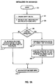
- step 200 by creating an empty dialog box, i.e., with none of its fields filled, in step 201.
- the threshold list is initialized.
- the process for initializing the threshold list is specified in greater detail in connection with FIG. 5B below.
- step 205 a test is performed to determine whether there are any existing sets of parameter ranges. If there are, for each parameter range set in the list, display it on the screen within the control window.
- step 209 using the data for the first set of parameter ranges, the data fields in the lower half of the dialog box are filled in. If there are not any existing parameter ranges, the lower half of the dialog box is filled in with zeros or default data in step 211.
- step 213 the interface waits to begin accepting user input into the dialog box.
- step FIG. 5B the process for initializing the threshold list is described.
- the process begins in step 250 and creates an empty threshold list, in step 251.
- a pointer to the list is created and that pointer points to a null value, usually zero, because the list is initially empty.
- the pointer will always point to the first element in the list.
- step 253 the next set of parameter ranges from permanent storage, is read into the empty threshold list. As the process begins, the first set of parameter ranges will be read into the threshold list.
- step 255 a test is performed to determine whether there are anymore parameter range sets, if so, in step 257, the next set of parameter ranges from the file is read into the threshold list created in step 251.
- Step 253 reads data into a temporary storage buffer in RAM.
- Step 257 creates an element, copies the data into that element, and adds the element to the list. If there are no more parameter range sets, in step 259, the process of initializing the interface is notified that the threshold list is initialized.
- step 300 the process by which a user interacts with the interface to establish a set of parameter ranges is described.
- the process begins in step 300 where the system is waiting for user input, step 301. If user input is detected in step 303, a test is performed to determine whether the user has entered data into any of the data fields in the lower half of the dialog box. If so, in step 305, the appropriate parameter range is modified as well as the depiction of the parameter range within the control window to reflect the new data. In step 307, the process resumes waiting for user input. If the user input was not data in the data fields, the process returns to step 309 to determine whether the user pressed the left mouse button.
- step 311 the position of the hot-spot of the mouse pointer at the time the mouse button is pressed is recorded, this point defines one of the corners of the set of parameter ranges. A symbol such as a small square may be displayed in the control window at this point. If the user presses the mouse button in some region than the dialog box or in an inappropriate area of the dialog box, then the presentation manager knows to pass that input on to some other program, such as the desktop manager, or the presentation manager may cause the data field nearest the mouse pointer to be highlighted. When the user clicks in the appropriate region again, the program treats it as if nothing happened in between this click and the first click in the region.
- step 311 After a first position of the mouse pointer is recorded in step 311, the test performed in step 313 detects a second depression of the left mouse button. In step 315, a second position of mouse pointer is recorded. This point defines the second corner of the parameter ranges. In step 317, a rectangle is drawn from the first position to the second position and possibly shaded to note that it is a completed parameter set. If desired the system may keep track of the mouse position and draw a dotted line between the first position and the current position of the mouse pointer. These steps are not illustrated in the figure.
- step 321 determines that the user pressed the right mouse button and the step in step 323 determines that the mouse pointer is on an existing range
- step 325 the data for that set of parameter ranges is read, and in step 327 that data is displayed in the data fields. If the test in step 329 determines that the user pressed "save”, then in step 331 that set of parameter ranges is saved into a database or data file. The process continues to wait for user input until the user closes the dialog box.
- FIG. 7 depicts one state machine used to determine whether conditions are met.
- the x-axis is time and the y-axis is some data "D" time which will be measured as an interval of time and that "D" will be measured with respect to whether it falls within the range specified.
- the home state 400 is the initial state of the state machine when the data stream begins to be parsed. As long as "D" is not in the range, path 401 is taken returning the state machine to the home state.
- path 403 is taken which starts the timer and monitors the data in the monitor state 404. If “D” exits the range before the allotted time interval has been satisfied, state machine returns along path 405 to the home state 400. If, however, "D" stays within the range and time "T” is satisfied, the state machine returns to home state along path 407, where the threshold structure and the values of "T” and “D” are sent to the monitoring module and the timer is stopped.
- the monitoring program handles the determination of the actual alarms based on the relationships which the range may have with other ranges. For example, if there was an "and" relationship, the monitoring program would look to a second state machine to determine whether the range conditions of a second set of parameters were satisfied before alerting users or taking other actions.
- Each data structure would include a plurality of data fields for the containing information about the set of parameter ranges. These fields would include a type field 450, which would determine whether the ranges were absolute values, represented intervals within the parameters, e.g., five minutes or a change in temperature of 50 C or percentage changes. There would also be an x-range field 451 for the lower and upper values of the parameter along the x-axis and a y-range field 453 for the lower and upper values of the parameter portrayed along the y-axis.
- the action field 454 which would contain the action to perform when the ranges are satisfied or exceeded.
- presentation fields 455, 456 containing information about the color or shading style by which this set of parameter ranges should be portrayed within the control window.
- the relation list field 457 would provide a pointer to the list of relation list types which allows this range to be related to other parameter ranges.
- the threshold id field 458 would contain a number or name which is unique to this set of parameter ranges.
- Other optional fields include a descriptive text field 459 which would describe a set of parameters and could be displayed within the parameter range on the control window and a unit of measurement field 460 containing, for example, "meters”, “megabytes”, or other units of measure as appropriate.
- FIG. 8 also shows a relation list type data structure which allows the set of parameter ranges to be combined with other parameter range sets.
- the relation field 471 would include information on the type of the relationship to the other parameter ranges such as and, or, nor, exclusive or and so forth.
- the threshold id field 472, would contain the id of the related threshold.
- the actual interface may be a list, a tree or other sorted data structure of elements of type "threshold-type".
- a threshold i.e., a set of ranges is satisfied
- data is sent to the monitor module. That data consists of the threshold elements data structures which comprises the sets of parameter ranges which were satisfied as well as the actual data measured.
Landscapes
- Engineering & Computer Science (AREA)
- Theoretical Computer Science (AREA)
- General Engineering & Computer Science (AREA)
- Human Computer Interaction (AREA)
- Physics & Mathematics (AREA)
- General Physics & Mathematics (AREA)
- Digital Computer Display Output (AREA)
- User Interface Of Digital Computer (AREA)
- Position Input By Displaying (AREA)
Applications Claiming Priority (2)
| Application Number | Priority Date | Filing Date | Title |
|---|---|---|---|
| US15786293A | 1993-11-19 | 1993-11-19 | |
| US157862 | 1993-11-19 |
Publications (1)
| Publication Number | Publication Date |
|---|---|
| EP0654728A2 true EP0654728A2 (de) | 1995-05-24 |
Family
ID=22565596
Family Applications (1)
| Application Number | Title | Priority Date | Filing Date |
|---|---|---|---|
| EP94308537A Withdrawn EP0654728A2 (de) | 1993-11-19 | 1994-11-18 | Graphische Einstellung von Parameterbereichen für Betriebsausführungssteuerung |
Country Status (4)
| Country | Link |
|---|---|
| US (1) | US5680560A (de) |
| EP (1) | EP0654728A2 (de) |
| JP (1) | JPH07200227A (de) |
| KR (1) | KR0140548B1 (de) |
Cited By (2)
| Publication number | Priority date | Publication date | Assignee | Title |
|---|---|---|---|---|
| WO1999034280A1 (en) * | 1997-12-29 | 1999-07-08 | Koninklijke Philips Electronics N.V. | Graphical user interface for weighting input parameters |
| EP1457867A1 (de) * | 2003-03-14 | 2004-09-15 | Koninklijke Philips Electronics N.V. | System zur Einstellung einer Kombination von Steuerungsparametern |
Families Citing this family (18)
| Publication number | Priority date | Publication date | Assignee | Title |
|---|---|---|---|---|
| US5877758A (en) * | 1996-11-22 | 1999-03-02 | Microsoft Corporation | System and method for using a slider control for controlling parameters of a display item |
| WO2000063841A1 (en) * | 1999-04-21 | 2000-10-26 | Spss Inc. | Computer method and apparatus for creating visible graphics by using a graph algebra |
| US6850254B1 (en) | 1999-12-02 | 2005-02-01 | International Business Machines Corporation | System and method for defining parameter relationship on user interfaces |
| US6661434B1 (en) * | 2000-04-13 | 2003-12-09 | International Business Machines Corporation | Method and system for displaying status of critical indicators on diverse display devices |
| US6600499B1 (en) * | 2000-04-13 | 2003-07-29 | International Business Machines Corp. | Method and system for displaying status of critical indicators on diverse display devices and indicating changes in status |
| US6636243B1 (en) * | 2000-04-13 | 2003-10-21 | International Business Machines Corp. | Method and system for displaying status of critical indicators on diverse display devices and indicating a history of status changes |
| JP2004501464A (ja) * | 2000-06-22 | 2004-01-15 | コーニンクレッカ フィリップス エレクトロニクス エヌ ヴィ | パラメータ制御システム |
| US7237205B2 (en) * | 2000-07-12 | 2007-06-26 | Home-Medicine (Usa), Inc. | Parameter evaluation system |
| US6949073B2 (en) * | 2002-10-03 | 2005-09-27 | Home-Medicine.Com, Inc. | Dyspnea monitor, and telemedicine system and method |
| US8043224B2 (en) | 2000-07-12 | 2011-10-25 | Dimicine Research It, Llc | Telemedicine system |
| US6603477B1 (en) | 2000-08-11 | 2003-08-05 | Ppg Industries Ohio, Inc. | Method of rendering a graphical display based on user's selection of display variables |
| JP4387611B2 (ja) * | 2001-06-07 | 2009-12-16 | 富士通マイクロエレクトロニクス株式会社 | 描画装置及び描画方法 |
| US20030095144A1 (en) * | 2001-11-21 | 2003-05-22 | Trevino Scott E. | Method and apparatus for prescribing an imaging scan and determining user input validity |
| US20060250352A1 (en) * | 2005-05-05 | 2006-11-09 | Mice Technoligies, Inc. | System and method for improved cursor functionality |
| US20060293767A1 (en) * | 2005-06-28 | 2006-12-28 | Eischeid Todd M | Policy based automation rule selection control system |
| PL2197647T3 (pl) | 2007-09-27 | 2013-03-29 | Henkel Corp | Dwuskładnikowy, wodorozcieńczalny, półtrwały środek antyadhezyjny o wysokim połysku do podłoży poliestrowych |
| US8665375B2 (en) * | 2009-06-22 | 2014-03-04 | Wsi Corporation | Apparatus and method for tracking the location of a pointing element in a cropped video field |
| KR20120019244A (ko) * | 2010-08-25 | 2012-03-06 | 삼성전자주식회사 | 휴대 단말기의 복합 속성 제어 방법 및 이를 지원하는 휴대 단말기 |
Family Cites Families (17)
| Publication number | Priority date | Publication date | Assignee | Title |
|---|---|---|---|---|
| JPS57171990A (en) * | 1981-04-16 | 1982-10-22 | Toyo Jozo Co Ltd | Novel compound a11725n1 and its preparation |
| JPH0640197B2 (ja) * | 1986-02-12 | 1994-05-25 | 富士写真フイルム株式会社 | 写真焼付露光量決定方法 |
| JP2606819B2 (ja) * | 1986-02-13 | 1997-05-07 | カシオ計算機株式会社 | グラフ表示装置 |
| JPS62203258A (ja) * | 1986-03-03 | 1987-09-07 | Casio Comput Co Ltd | グラフ表示機能を備えた小型電子式計算機 |
| JPH0812206B2 (ja) * | 1986-03-07 | 1996-02-07 | ヒューレット・パッカード・カンパニー | 測定器制御装置 |
| JPH0229866A (ja) * | 1988-07-20 | 1990-01-31 | Hitachi Ltd | 臨床検査システムの異常検体表示方法 |
| US5016170A (en) * | 1988-09-22 | 1991-05-14 | Pollalis Spiro N | Task management |
| US5337405A (en) * | 1990-10-02 | 1994-08-09 | Hewlett-Packard Company | Guided data presentation |
| US5247284A (en) * | 1991-04-30 | 1993-09-21 | International Business Machines Corporation | Graphical method of inputing time values |
| US5375199A (en) * | 1991-06-04 | 1994-12-20 | Digital Equipment Corporation | System monitoring method and device including a graphical user interface to view and manipulate system information |
| JP2714273B2 (ja) * | 1991-06-28 | 1998-02-16 | 株式会社東芝 | プラント監視装置およびプロセス入力点選択支援装置 |
| US5270806A (en) * | 1991-10-07 | 1993-12-14 | Xerox Corporation | Image editing system and method having improved multi-dimensional editing controls |
| US5365360A (en) * | 1991-11-15 | 1994-11-15 | International Business Machines Corporation | Method and apparatus for presenting information contained within a data icon by assigning attributes to various dimensions of the data icon |
| JPH05314269A (ja) * | 1992-05-11 | 1993-11-26 | Toshiba Corp | グラフ作成装置 |
| JPH05324238A (ja) * | 1992-05-26 | 1993-12-07 | Fujitsu Ltd | グラフによる数量決定方法 |
| US5479592A (en) * | 1994-03-01 | 1995-12-26 | Stenhouse; Michael S. | Method of simultaneously analyzing a plurality of performance statistics of an athlete |
| US5500938A (en) * | 1994-03-07 | 1996-03-19 | International Business Machines, Corporation | Method and apparatus for directly selecting and signalling start and stop times in an electronic calendar |
-
1994
- 1994-10-19 KR KR1019940026720A patent/KR0140548B1/ko not_active Expired - Fee Related
- 1994-10-26 JP JP6262934A patent/JPH07200227A/ja active Pending
- 1994-11-18 EP EP94308537A patent/EP0654728A2/de not_active Withdrawn
-
1995
- 1995-09-27 US US08/534,520 patent/US5680560A/en not_active Expired - Fee Related
Cited By (4)
| Publication number | Priority date | Publication date | Assignee | Title |
|---|---|---|---|---|
| WO1999034280A1 (en) * | 1997-12-29 | 1999-07-08 | Koninklijke Philips Electronics N.V. | Graphical user interface for weighting input parameters |
| EP1457867A1 (de) * | 2003-03-14 | 2004-09-15 | Koninklijke Philips Electronics N.V. | System zur Einstellung einer Kombination von Steuerungsparametern |
| WO2004081782A1 (en) * | 2003-03-14 | 2004-09-23 | Koninklijke Philips Electronics N.V. | System for adjusting a combination of control parameters |
| US8938676B2 (en) | 2003-03-14 | 2015-01-20 | Koninklijke Philips N.V. | System for adjusting a combination of control parameters |
Also Published As
| Publication number | Publication date |
|---|---|
| JPH07200227A (ja) | 1995-08-04 |
| KR950015136A (ko) | 1995-06-16 |
| KR0140548B1 (ko) | 1998-07-01 |
| US5680560A (en) | 1997-10-21 |
Similar Documents
| Publication | Publication Date | Title |
|---|---|---|
| US5680560A (en) | Method and device for graphically setting multiple parameter ranges | |
| US5384910A (en) | Method and apparatus for facilitating operator reconfiguration of a graphical user interface in a data processing system | |
| US5808611A (en) | Positioning for multiple icons in an object-oriented interface | |
| EP0660220B1 (de) | Verschiebungs- und Entladungsoperationen in einer graphischen Benutzerschnittstelle | |
| KR950014983B1 (ko) | 컴퓨터 디스플레이 스크린상에 윈도우를 능률적으로 디스플레이시키는 방법 | |
| US8140971B2 (en) | Dynamic and intelligent hover assistance | |
| US5680562A (en) | Computer system with graphical user interface including automated enclosures | |
| US5706448A (en) | Method and system for manipulating data through a graphic user interface within a data processing system | |
| US6816176B2 (en) | Temporarily moving adjacent or overlapping icons away from specific icons being approached by an on-screen pointer on user interactive display interfaces | |
| US6844887B2 (en) | Alternate reduced size on-screen pointers for accessing selectable icons in high icon density regions of user interactive display interfaces | |
| US6201539B1 (en) | Method and system for customizing a data processing system graphical user interface | |
| US6452617B1 (en) | Adjusting a click time threshold for a graphical user interface | |
| US5220675A (en) | Method and system for customizing a user interface in an integrated environment | |
| US5960199A (en) | Model trace view for object-oriented systems | |
| EP1086418B1 (de) | Verfahren zur dynamischen darstellung der kommandos eines toolbars in abhängigkeit von deren benutzung | |
| US5767850A (en) | Relocatable menu icon for accessing an application in a graphical user interface | |
| US7269797B1 (en) | Mechanism to organize windows in a graphic application | |
| US20020154173A1 (en) | Graphical user interface for direct control of display of data | |
| US20040098406A1 (en) | System for iteratively designing an object heterarchy in an object-oriented computing environment | |
| US5621879A (en) | Window management information input/output system | |
| US5818449A (en) | System and method for renaming a window title | |
| US20030043213A1 (en) | Computer controlled user interactive display interface implementation for modifying the scope of selectivity of an on-screen pointer | |
| GB2360921A (en) | Tabbed notebook having a common registry | |
| KR20040018663A (ko) | 디스플레이 시스템의 아이콘 제어방법 | |
| JPH0498310A (ja) | コンピュータのメニュー方式マンマシンインタフェースシステム |
Legal Events
| Date | Code | Title | Description |
|---|---|---|---|
| PUAI | Public reference made under article 153(3) epc to a published international application that has entered the european phase |
Free format text: ORIGINAL CODE: 0009012 |
|
| AK | Designated contracting states |
Kind code of ref document: A2 Designated state(s): DE FR GB |
|
| 17P | Request for examination filed |
Effective date: 19950907 |
|
| STAA | Information on the status of an ep patent application or granted ep patent |
Free format text: STATUS: THE APPLICATION HAS BEEN WITHDRAWN |
|
| 18W | Application withdrawn |
Withdrawal date: 19960927 |