EP0654747B2 - Banddrucker - Google Patents
Banddrucker Download PDFInfo
- Publication number
- EP0654747B2 EP0654747B2 EP94118529A EP94118529A EP0654747B2 EP 0654747 B2 EP0654747 B2 EP 0654747B2 EP 94118529 A EP94118529 A EP 94118529A EP 94118529 A EP94118529 A EP 94118529A EP 0654747 B2 EP0654747 B2 EP 0654747B2
- Authority
- EP
- European Patent Office
- Prior art keywords
- data
- character string
- bar code
- incremented
- Prior art date
- Legal status (The legal status is an assumption and is not a legal conclusion. Google has not performed a legal analysis and makes no representation as to the accuracy of the status listed.)
- Expired - Lifetime
Links
Images


Classifications
-
- B—PERFORMING OPERATIONS; TRANSPORTING
- B41—PRINTING; LINING MACHINES; TYPEWRITERS; STAMPS
- B41J—TYPEWRITERS; SELECTIVE PRINTING MECHANISMS, i.e. MECHANISMS PRINTING OTHERWISE THAN FROM A FORME; CORRECTION OF TYPOGRAPHICAL ERRORS
- B41J3/00—Typewriters or selective printing or marking mechanisms characterised by the purpose for which they are constructed
- B41J3/01—Typewriters or selective printing or marking mechanisms characterised by the purpose for which they are constructed for special character, e.g. for Chinese characters or barcodes
-
- B—PERFORMING OPERATIONS; TRANSPORTING
- B41—PRINTING; LINING MACHINES; TYPEWRITERS; STAMPS
- B41J—TYPEWRITERS; SELECTIVE PRINTING MECHANISMS, i.e. MECHANISMS PRINTING OTHERWISE THAN FROM A FORME; CORRECTION OF TYPOGRAPHICAL ERRORS
- B41J3/00—Typewriters or selective printing or marking mechanisms characterised by the purpose for which they are constructed
- B41J3/407—Typewriters or selective printing or marking mechanisms characterised by the purpose for which they are constructed for marking on special material
- B41J3/4075—Tape printers; Label printers
-
- G—PHYSICS
- G06—COMPUTING OR CALCULATING; COUNTING
- G06K—GRAPHICAL DATA READING; PRESENTATION OF DATA; RECORD CARRIERS; HANDLING RECORD CARRIERS
- G06K1/00—Methods or arrangements for marking the record carrier in digital fashion
- G06K1/12—Methods or arrangements for marking the record carrier in digital fashion otherwise than by punching
Definitions
- the present invention relates to a tape printing device for printing desired bar codes on a tape.
- Japanese Patent Application Kokai No. HEI-5-177898 has proposed a tape printer including a keyboard, a display, and a print mechanism.
- the print mechanism is capable of printing characters, such as letters, symbols, and the like, on different width tapes (for example, 12 mm and 18 mm wide tapes) that are housed in cassettes.
- the tape mechanism is capable of printing bar codes on the tape with and in addition to the characters.
- the tape printer described in Japanese Patent Application Kokai No. HEI-5-177898 is well-suited printing file names on tapes that can be adhered to the back of files as identification labels.
- JP-A-5 185 695 has proposed a tape printer for printing numbered character strings, made from inputted strings of numbers, on a tape while numbering processes are performed to increment numbering of successive character strings.
- This publication has proposed a structure also capable of performing numbering processes by incrementing or counting up at a line order of alphabetic characters.
- the printer described in Japanese Patent Application Kokai No. HEI-5-177898 allows printing bar codes based on effective characters that are made from inputted numbers, characters, and the like.
- the printer described in Japanese Patent Application Kokai No. HEI-5-185695 allows performing numbering processes on numbered character strings (made from strings of numbers), but not on bar codes.
- the bar code printer comprises input means for inputting data indicative of a bar code desired to be printed on a tape, storage means for temporarily storing the inputted data print data generation means for producing print data for the desired bar code and printing means for receiving the print data and for printing images of the desired bar code on a print tape.
- US-A-4939674 discloses a label generation apparatus which enables the user to define a label of arbitrary size, shape and characteristics.
- the label indicia are generated in both machine-readable and human-readable form, where the machine-readable includes bar codes and the human-readable includes alpha-numeric.
- the generation includes the facility to transmit the coding for the indicia and to match the data in an input data file.
- the label indicia can be numbered according to any predetermined ordering that is required by the user. This can be a sequential numbering, an ordered series, or correspondence to any input data file provided by the user. Thus, label count and label indicia value record are maintained separately since the label numbering may not be sequential and may not match the label count.
- a first tape print device will be described with reference to Figs. 1 through 24, which does not represent the invention.
- the tape printer includes: an input unit A; a data storage unit B; a displaying unit C; a printing unit D; a print data generating unit E; and an incrementing unit F.
- the input unit A is for inputting data of a character string made from a plurality of characters, such as letters, numbers and symbols, indicative of a bar code desired to be printed on a tape and various commands.
- the data storage unit B is for temporarily storing the inputted data of the character string indicative of the desired bar code.
- the displaying unit C is for receiving the data stored in the data storage unit B and for displaying the data.
- the printing unit D has a print head equipped with a plurality of printing elements for printing dot images.
- the print data generating unit E is for receiving the data from the data storage unit B, producing dot image data for printing, and outputting the dot image data to the printing unit D.
- the data of the character string indicative of the desired bar code is constructed from a common character string and a countable character string. Every time when the printing unit D performs a printing operation for printing the data from the data storage unit B, the incrementing unit F increments the countable character string. The incrementing unit F updates the data of the countable character string stored in the storage unit B with the data of the incremented countable character string.
- the incrementing unit F thus repeatedly increments the countable character string of the data stored in the storage unit B while not incrementing the common character string, based on which the print data generating unit E repeatedly generates dot image data to cause the printing unit D to repeatedly print the data onto a tape.
- the tape is printed with a plurality of bar codes, with their countable character string being serially incremented.
- the plurality of bar codes with their countable character strings being serially incremented, are printed on the tape, by merely inputting data of the first one of the plurality of bar codes.
- the tape print device may further include a numbering part setting unit G.
- This numbering part setting unit G is for receiving a predetermined command for executing the numbering or incrementing process and for setting a part of the character string of the data stored in the data storage unit B, that are desired to be subjected to the numbering processes to be attained by the incrementing unit F.
- the setting unit G sets data indicative of start and stop positions of the part desired to be subjected to the numbering process, between which both the common character string and the countable character string of the character string for the bar code are entirely located.
- the setting unit G then stores the data for the start and stop positions in the data storage unit B.
- the incrementing unit F increments only the countable character string, even though the setting unit G thus sets the entire part of the character string to be subjected to the incrementing process.
- the tape print device may preferably calculate a check digit data relating to the inputted data of the character string composed of the common character string and the countable character string.
- the incrementing unit F may preferably calculate the check digit data relating to the common character string and the incremented countable character string.
- the data storage unit B stores, as the updated bar code data, the data for the common character string and the incremented countable character string as well as the check digit data thus calculated for the incremented countable character string and the common character string.
- This example is a tape printer capable of printing, on a print tape, character strings or bar codes representative of character strings. It is noted that a character string is made from a series of a plurality of characters, such as alphabetic letters, numbers and symbols.
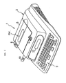
- a keyboard 3 is disposed in front of a body frame 2 of a tape printing apparatus 1
- a printing mechanism PM is provided at the rear of the keyboard 3 and within the body frame 2
- Reference numeral 4 denotes a release button for opening a cover frame 6 when a tape containing cassette CS, to be loaded in the printing mechanism PM, is put in or removed.
- Reference numeral 5 denotes a cut operating button for manually cutting a print tape 19.
- keyboard 3 there are arranged such keys as character keys for inputting character code data of characters (i.e., alphabetic letters, numbers, and symbols,) a space key, a return key, cursor move keys (cursor move right key, cursor move left key, cursor move up key and cursor move down key) for moving a cursor K rightwardly, leftwardly, upwardly and downwardly, a size setting key for setting a desired size of characters to be printed, a bar code key for instructing input of bar code data, a numbering part setting key for setting a part of the inputted character string or the inputted bar code desired to be subjected to a numbering process, a bar code standard format setting key, a print key for commanding printing, an execution key for finalizing various types of setting, a cancel key for canceling the content which has been set, and a power key for turning power on/off.
- character keys for inputting character code data of characters (i.e., alphabetic letters, numbers, and symbols,)
- a space key a
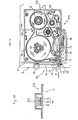
- the rectangular, tape containing cassette CS is removably loaded in the printing mechanism PM.
- a tape spool 8 around which a transparent laminate film 7 is wound
- a ribbon supply spool 10 around which a print ribbon 9 is wound
- a take-up spool 11 for taking up the print ribbon 9
- a supply spool 13 around which a double coated tape 12 with the same width as the laminate film 7 is wound with its peeling paper on the outside
- a joining roller 14 for causing the double-coated tape 12 to adhere to the laminate film 7.
- the double-coated tape 12 is a tape having adhesive layers formed on both sides of its base tape and having peeling paper attached to the adhesive layer on one side.
- a thermal head 15 (print head) is installed upright in the position where the laminate film 7 and the print ribbon 9 overlap each other.
- a platen roller 16 for pressing the laminate film 7 and the print ribbon 9 against the thermal head 15 and a feed roller 17 for pressing the laminate film 7 and the double coated tape 12 against the joining roller 14 to thereby form the print tape 19 are pivotally supported for rotation on a support member 18 which is pivotally mounted for rotation on the body frame 2.
- a manual cutting mechanism 30 for cutting the print tape 19 will be described in detail below.
- a plate-formed auxiliary frame 31 in upright position and a stationary blade 32 is fixedly attached to the auxiliary frame 31 so as to face in an upward direction.
- An operating lever 34 extended in the direction from front to rear is supported for rotation, at its portion closer to the front end, on a pivot shaft 33 fixedly attached to the auxiliary frame 31.
- a movable blade 35 is fixedly attached to the operating lever 34 in front of the pivot shaft 33 such that it opposes the stationary blade 32.
- the rear end portion of the operating lever 34 is positioned under the cut operating button 5.
- the operating lever 34 is resiliently urged by a spring member, not shown, in the direction to separate the movable blade 35 from the stationary blade 32.
- the print tape 19 having a character string or a bar code printed thereon passes through the space between the stationary blade 32 and the movable blade 35 and sticks out of the body frame 2. Then, if the cut operating button 5 is pressed down, the movable blade 35 is caused to approach the stationary blade 32 by the movement of the operating lever 34 and, then, the print tape 19 is cut by the blades 32 and 35.
- each tape containing cassette CS As the print tape 19 to be fed from the tape containing cassette CS (i.e., the double-coated tape 12 and the laminate film 7 mounted in the cassette CS), there are provided those of five tape widths, 6 mm, 9 mm, 12 mm, 18 mm, and 24 mm.
- On the bottom wall of each tape containing cassette CS there is provided a projecting piece 20.
- the projecting piece 20 formed on each tape cassette CS is for indicating a tape width of a tape 19 to be obtained from the tape cassette CS, i.e., the width of the double-coated tape 12 and the laminate film 7 mounted in the cassette CS. Because the width is either one of the five tape widths, the projecting piece 20 formed on each tape cassette CS is formed of three projecting claws, for distinguishing in combination one from the five tape widths.
- a cassette sensor 42 at a position confronting the projecting piece 20 when the tape cassette CS is loaded in the printing mechanism portion PM.
- the cassette sensor 42 is for detecting the condition of the projecting claws of the projecting piece 20 to thereby detect the tape width of a tape to be obtained from the tape cassette CS actually loaded in the printing mechanism portion PM.
- the cassette sensor 42 is made from three photocouplers S, each having a light-emitting diode paired with a photodetector. Each of the three photocouplers is located at a position capable of receiving a corresponding one of the three projecting claws of the projecting piece 20. Each photosensor therefore detects whether or not the corresponding projecting claw is inserted between the light-emitting diode and the photodetector.
- the control system of the tape printing apparatus 1 is structured as shown in the block diagram of Fig. 4.
- An input/output interface 50 of a controller C is connected with the keyboard 3, the cassette switch 42, a display controller (LCDC) 23 having a video RAM 24 for outputting display data to the liquid crystal display (LCD) 22, a drive circuit 46 for an alarming buzzer 45, a drive circuit 48 for driving the thermal head 15, and a drive circuit 49 for driving the tape feed motor 47.
- LCDC display controller
- the controller C includes a CPU 52 and the input/output interface 50, a CGROM 53, ROMs 54 and 55, and a RAM 60 connected to the CPU 52 with a bus 51 such as a data bus.
- the CGROM 53 stores dot pattern data for displaying each of a plurality of characters, such as alphabetic letters, numbers and symbols, correspondently to a plurality of code data inputtable through operation of the-character keys, on the key board 3.
- the ROM (dot pattern data memory) 54 stores dot pattern data for printing a plurality of characters, such as alphabetic letters, numbers and symbols, correspondently to the plurality of code data inputtable through operation of the character keys on the key board 3.
- the dot pattern data of each character is stored for each of a plurality of typefaces (such as Gothic type and Ming-cho type), at each of seven print character sizes (16, 24, 32, 48, 64, 96, and 128 dot sizes).
- the ROM 54 further stores dot pattern data for printing a plurality of bar code modular data.
- the ROM 55 stores various programs including a display drive control program for controlling the display controller 23 according to character code data, which represent characters, such as letters, numbers, symbols and the like, that are inputted through the keyboard 3; a print drive control program for serially retrieving data from a print data buffer 66 and driving the tape feed motor 47, the thermal head 15, and the like; and a tape print control program (to be described later), which is special characteristic of the present invention.
- the tape print control program includes a subroutine for controlling bar code data conversion processes for converting the bar code data (character code data of an effective character string stored in the text memory 61) into bar code modular data, based on a desired bar code standard format, such as code standard formats of CODE-39 and EAN-12 (Europe Article Number-13).
- the RAM 60 is formed with a text memory 61, a pointer buffer 62, a bar code buffer 63, a bar code parameter memory 64, a count memory 65, and the print data buffer 66.
- the bar code buffer 63 is for preparing bar code data made from character code data of an effective character string representative of a desired bar code.
- the effective character string is made from: a character string which is inputted from the key board 3 and which is made from a plurality of characters, such as letters, numbers, symbols; and other characters prepared for producing the desired bar code.
- the text memory 61 is for temporarily storing text data.
- the text data is made from character code data of a normal character string inputted from the keyboard 3 or the bar code data prepared in the bar code buffer 33.
- a pointer value TP for indicating an address in the text memory 61 is stored in the pointer buffer 62.
- the bar code parameter memory 64 is for storing data indicating: name of a bar code standard format by which a bar code is desired to be produced; an effective digit number of an effective character string convertable into a desired bar code modular data according to the desired bar code standard format, necessity or unnecessity of calculating a check digit for the inputted characters for the desired bar code according to the desired bar code standard format.
- the count memory 65 is for storing data (count number I) indicating the number of times numbering processes are desired to be repeatedly performed.
- the print data buffer 66 is for temporarily storing print dot pattern data for the desired bar code or the desired normal character string for printing.
- the print dot pattern data for the normal character string is produced based on the character code data of the inputted characters stored in the text memory 61 and the dot pattern data stored in the ROM 54.
- the print dot pattern data for the bar code is produced based on the dot pattern data stored in the ROM 54 and bar code modular data which are produced based on the character code data (bar code data) of the effective character string stored in the text memory 61 through the subroutine for the bar code data conversion process.
- This control starts when the power source is turned on by manipulating the power source key on the keyboard 3.
- the memories 61 through 66 in the RAM 60 are cleared, an initial setting process for initializing the print mechanism PM is executed, and a text data inputting screen is displayed on the display 22 for inputting text data (character code data of a normal character string) desired to be printed on a tape.
- a bar code input screen is first displayed on the display 22 (S25) for inputting a bar code.
- An initial code for the bar code is first stored in the bar code buffer 63, and the initial mark SM is displayed (S26).
- the initial code is stored in the third storage address of the bar code buffer 63 as shown in Fig. 13, and a triangular initial mark SM is displayed at the left lead position of the bar code input screen as shown in Fig. 19.
- bar code parameter data BCPD including data on effective digit number, check digit, and name of bar code standard format with which the bar code data is desired to be produced, will be stored in the lead storage address of the bar code buffer 63.
- Check digit information data CDI for checking the necessity or unnecessity of calculating check digit data will be stored in the second storage address of the bar code buffer 63, as will be described below.
- a screen for setting the standard format of the bar code is displayed on the display 22 (S45).
- a frame is formed in the display 22, and titles such as "Standard Format Name", "C/D” (check digit), and "Effective Digit Number” are displayed directly above the frame.
- a default standard format (“CODE 39”, for example) is displayed at the position labeled "Standard Format Name”.
- a default data (“Necessity”, for example) is displayed for "C/D”
- a default data (“2", for example) is displayed for "Effective Digit Number”.
- a block cursor BK is provided for setting each one of the "Standard Format Name", "C/D" (check digit), and "Effective Digit Number".
- Fig. 20 shows the case where a block cursor BK is located for setting the standard format name.
- the default standard format "CODE 39" is reversely displayed. More specifically, colors at which characters and background are displayed in the block cursor BK are reversed to those at which characters and background are displayed normally outside of the block cursor BK.
- the block cursor BK moves to the preceding or succeeding category, the results are displayed (S51), and the program returns to S46.
- the block cursor BK will proceed to the position of "C/D” (check digit) to reversely display "Necessity” when the cursor move right key is manipulated and further to the position of "Effective Digit Number” to reversely display "2" if the cursor move right key is manipulated again.
- the setting data preceding or succeeding the setting data presently displayed within the block cursor BK is displayed (S52) and the program returns to S46.
- the block cursor BK is positioned to display the setting data "CODE 39" therein, the displayed content will change to "EAN-13" when the cursor move up key is manipulated and back to "CODE 39" if the cursor move up key is manipulated again.
- the execution key when the execution key is manipulated (i.e., S46 is YES, S47 and S48 are NO, and S49 is YES), the three displayed setting data are stored in respective predetermined storage regions of the bar code parameter memory 64 of the RAM 60 and, based on these setting data, bar code parameter data BCPD and check digit information data CDI are stored in the bar code buffer 63 (S53). Then, this control is ended and the program returns to S32 of the bar code data input process control of Fig. 6. For example, manipulating the execution key when the "CODE 39", “Necessity", and "8" are displayed as shown in Fig. 20, these three setting data are stored separately in the bar code parameter memory 64. It is noted that when the setting data of the bar code standard format name of "CODE 39" is set, the start code * (SAC) is stored in the bar code buffer 63 at an address following the address at which the initial code is stored.
- SAC start code *
- the bar code input screen is displayed on the display 22 (S32), whereupon the program returns to S27.
- the standard of "CODE 39" is set, as shown in Fig. 19, the start mark "*" is displayed on the display 22 after the initial mark SM.
- the cancel key is manipulated during the bar code standard setting process control of Fig. 7 (i.e., S46 is YES, S47 through S49 are NO, and S50 is YES)
- S46 is YES
- S47 through S49 are NO
- S50 is YES
- the check digit data is set to be necessarily calculated, and the effective digit number of "8" is set.
- the start code (*), the stop code (*), the check digit code, and a character string, constructed from five (5) characters inputted from the key board 3, make up an effective character string of the eight (8) effective digit number.
- the step S33 judges whether the number of the characters inputted from the key board 3 exceeds the number "5" corresponding to the effective digit number "8".
- the calculated check digit value (C/D) of [-(hyphen)], the stop code * (SOC), and the end code are added to the character string "A B C 1 2", and are stored in the bar code buffer 63 as shown in Fig. 13. All the bar code data are then stored in the text memory 61 as text data as shown in Fig. 14.
- the simplified bar code symbol BK is displayed on the display 22 together with an initial mark SM and an end mark EM corresponding to the end code, as shown in Fig. 21.
- the cursor right move key is operated to move the cursor K to number "3" after when the numbering part setting key is manipulated.
- Manipulating the execution key thereafter causes the number string "1 2 3" to be reversely displayed.
- the lead code and the tail code are therefore stored in the text memory 61 inserted respectively before and after the number string to be subjected to numbering, that is, "1 2 3", as shown in Fig. 15.
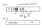
- the lead mark TM and the tail mark LM are displayed inserted respectively before and after the character string "1 2 3" to be subjected to numbering as shown in Fig. 18.
- this numbering setting key when numbering processes are desired to be performed on bar code data, this numbering setting key allows collective setting of the character string to undergo numbering.
- the part “A B C” (letter string) is a common character string desired to be printed common with each numbered bar code.
- the letter string “A B C” should not be incremented in the numbering process.
- the part “1 2” (number string) is a countable character string desired to be incremented through the numbering process.
- the entire character string “A B C 1 2" is collectively set to subjected to the numbering process.
- print process control (refer to Fig. 9) is executed (S19).
- the print dot image data is produced based on the bar code modular data and the dot pattern data stored in the ROM 54.
- print dot image data is stored in the print data buffer 66 (S73).
- the print dot image data is then outputted from the print data buffer 66 to the print mechanism PM (S74) for printing. More specifically, the print drive control is achieved for serially retrieving the data from the print data buffer, and the motor 47 and the thermal head 15 are driven to perform the printing operation.
- the program enters a waiting period until the print mechanism PM ends printing operations for printing the print dot image data onto the print tape 19 (i.e., S80 is YES). Then, this control ends, and the program returns to S11 of Fig. 5.
- a process control for setting a target number up to which the numbering processes are desired to be repeatedly performed is executed (S72).
- a set screen is displayed on the display 22 for setting the numbering process target number.
- S73 and S74 are executed to generate print dot image data for the text data presently stored in the text memory 61. Then, the print mechanism PM performs printing processes on the print tape 19 based on the print dot image data.
- the address of the tail code (refer to TP0 of Fig. 15) is set to the pointer value TP (S86), at the start of this control (S85). Further, the pointer value TP is decremented by one (refer to TP1 of Fig. 15) (S87). Thus, the pointer TP indicates the tail character (lowest digit) of the part of the character string desired to be subjected to numbering process.
- the data stored at the address indicated by the pointer TP is retrieved (S88) from the text memory 61. If the data is not the lead code (i.e., S89 is NO), and if the data is not a number code (i.e., S90 is NO), the program returns to S87. On the other hand, if the retrieved data is a number code (i.e., S89 is NO and S90 is YES) and if the number code represents a number other than the number "9" (i.e., S91 is NO), the number represented by the number code is incremented, in accordance with the number arrangement order defined in the ASCII code. The number code is then replaced (S94) with the incremented number code, whereupon this control is ended and the program returns to S77 of the print process control of Fig. 9.
- the retrieved data is a number code (i.e., S89 is NO and S90 is YES) and the code is for the number "9" (i.e., S91 is YES)
- the code is replaced with a code for the number "0" (S93).
- S93 the number is not at the highest digit of the number string (i.e., S93 is NO)
- S87 et seq are executed.
- the address of the lowest digit is set to the pointer value TP (S95), and S88 et seq are executed.
- the count value I of the number of the numbering processes is decremented by one.
- the program goes into standby until the print mechanism completes printing operations (i.e., S79 is NO).
- S73 et seq are executed again for printing the incremented character string presently stored in the text memory.
- the count value I is reduced to the number "0" (i.e., S78 is YES) and printing operations are completed (i.e., S80 is YES)
- this control is ended, and the program returns to S11 of Fig. 5.
- the character string shown in Fig. 15 is stored in the text memory 61, and the number string "1 2 3" is set as the character string to be subjected to the numbering process.
- the target number for the numbering process is set to "2”
- the character string "J K 1 2 3 X Y Z" and a character string "J K 1 2 4 X Y Z" which is the result of the number string "1 2 3" being incremented by one, are serially printed into labels on the print tape 19 as shown in Fig. 23.
- the tail code address (refer to TP0 in Fig. 16) is set to the pointer value TP (S100). Then, this pointer value TP is decremented by one (refer to TP1 in Fig. 16) (S101). As a result, the pointer TP becomes to indicate the tail character code (end code) of the character string to be subjected to numbering.
- the data stored at the address indicated by the pointer TP is retrieved (S102) from the text memory 61. If this data is not the lead code (i.e., S103 is NO), and if this data is not a number code (i.e., S104 is NO), the program returns to S101. If the retrieved data is a number code (i.e., S103 is NO and S104 is YES), and if the number code is not the number code for the number "9" (i.e., S105 is NO), the number code is incremented in accordance with the number arrangement order defined in ASCII code (S108). Then, this control and incrementing process control are ended, and the program returns to S77 of the print process control of Fig. 9.
- the number code is replaced with the number code for the number "0" (S106).
- S101 et seq are executed.
- the address of the lowest digit of the number string is set in the pointer value TP (S109) and S102 et seq are executed. That is, when all the numbers constituting the number string are replaced to "0", the processes of the execution of S102 through S104, a NO determination in S105, and the execution of S108 increment the number of the lowest digit of the number string into "1".
- the manner of calculating the check digit value in S111 is predetermined depending on the standard format of the bar code. For example, when the bar code standard format "CODE-39" has been set, the calculation is attained in accordance with a well-known modulo 43 system. In the modulo 43 system, the following steps of calculation are attained.
- the value of the check digit for "A B C 1 3" is ".(period)"
- the value of the check digit for "A B C 1 2" is "-(hyphen)”.
- the number string is described as the countable character string while the letter string is described as the common character string.
- the countable character string can be made to include not only numbers but also alphabetic letters so that numbering processes can be performed while incrementing the alphabetic letters in the arrangement order based on the code font, for example ASCII.
- the present embodiment provides a tape print device capable of printing both a normal character string and a bar code onto a single tape label.
- a plurality of pairs of the normal character strings and the bar codes are printed on the tape while being simultaneously incremented. Accordingly, it is possible to easily obtain a plurality of tape labels, on which the serially incremented pairs of normal character string and bar code are printed.
- the normal character string may be made from an article identification number and/or article category-representing letter string, and represents the content of the bar code.
- Such labels can be attached to various articles as identification labels.
- the labels can be read out not only by the bar code reader but also by human visual inspection. Accordingly, it becomes possible to enhance efficiency of management control of the articles.
- the tape print device of the embodiment includes an input unit; a bar code data conversion unit; a display; a data storage unit; a print data conversion unit; a print data storage unit; a target number setting unit; a numbering part setting unit; a bar cord incrementing unit; a number string incrementing unit; and a printing unit.
- the input unit is for inputting letters and numbers and various commands.
- the bar code data conversion unit is for converting the inputted numbers into bar code data.
- the display is for displaying data indicative of a normal character string constructed from the inputted letters and numbers and the bar code data converted by the bar code data conversion unit from the inputted numbers.
- the data storage unit is for storing the data of the inputted normal character string and the bar code data converted by the bar code data conversion unit from the inputted numbers.
- the print data conversion unit is for converting the data of the normal character string and the bar code data stored in the data storage unit into dot pattern data for printing.
- the print data storage unit is for storing the dot pattern data.
- the target number setting unit is for setting a target number up to which both the normal character string data and the bar code data are desired to be serially incremented.
- the numbering part setting unit is for setting a part of each of the normal character string data and the bar code data desired to be serially incremented.
- the bar code incrementing unit is for serially incrementing the bar code data stored in the data storage unit and for repeatedly replacing the bar code data with the incremented bar code data from an initial value up to the target number set by the target number setting unit.
- the number string incrementing unit is for serially incrementing the code data of the number string among the normal character string stored in the data storage unit and for repeatedly replacing the number string code data with the incremented number string code data from the initial value up to the target number set by the target number setting unit.
- the printing unit is controlled by the dot pattern data stored in the print data storage unit to repeatedly print both the normal character string and the bar code symbol up to the set target number.
- This example is an application of the embodiment to a tape printer capable of printing on a print tape both a bar code produced through a JAN (Japan Article Number) bar code standard format and a character string representative of the bar code and constructed from characters, such as alphabetic letters, numbers and symbols.
- JAN Joint Article Number
- the overall structure of the tape printer of this example is the same as that of Fig. 2.
- the structure of the print mechanism PM employed in the tape printer of this example is also the same as that of Figs. 3A and 3B.
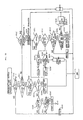
- the control system of the tape printer 1 of this example is structured as shown in the block diagram of Fig. 25.
- a controller C of this example includes a CPU 120, a ROM 121, a CGROM 123, an outline data ROM 124, a RAM 130, and an input/output interface 125.
- a bus fine 126 is provided for connecting the CPU 120, the ROM 121, the CGROM 123, the outline data ROM 124, and the RAM 130 with one another and for connecting them to the input/output interface 125.
- the ROM 121 is provided with a program memory 122 for storing various programs.
- the CPU 120 is for performing various calculations based on various programs stored in the ROM 121.
- the CGROM 123 stores dot pattern data for displaying each of a plurality of characters, correspondently to a plurality of character code data inputtable through operation of the character keys.
- the outline data ROM 124 stores outline data representative of outlines of a plurality of characters, correspondently to the plurality of character code data inputtable through operation of the character keys.
- the outline data for each character is stored for each of the plurality of typefaces (such as Gothic type and Ming-cho type).
- the outline data ROM 124 further stores outline data representative of outlines of a plurality of bar code modular data.
- the RAM 130 is for temporarily storing the results calculated by the CPU 120.
- the program memory 122 in the ROM 121 stores therein: a numbering part setting process control program 122a for setting a part of each of a normal character string and a bar code desired to be subjected to a numbering process; an increment process control program 122b for incrementing the part of the normal character string set in the numbering part setting process control program 122a; a bar code increment process control program 122c for incrementing the part of the bar code set in the numbering part setting process control program 122a; an image development process control program 122d for converting the outline data corresponding to the code data stored in a text memory 131 into dot pattern data and for developing the dot pattern data into a print buffer 134; a print process control program 122e for sequentially reading out the dot pattern data stored in the print buffer and for printing the dot pattern on the print tape 19 with the use of the print mechanism PM; a bar code data conversion process control program 122f for converting the numeric data, inputted at the time of bar code data inputting process, into bar
- the bar code data conversion process control program 122f is for converting thirteen numerical data (thirteen digit number including twelve digit number of characters and one digit number of modular check character) into bar code modular data through the JAN (Japan Article Number) standard format. More specifically, the thirteen digit number is converted into: three modules of data for a left-hand guard bars; forty-two (42) modules of data for left six data characters; five modules of data for center bar; thirty-five (35) modules of data for right five data characters; seven modules of data for modulo check character; three modules of data for right-hand guard bar, and the like.
- the RAM 130 is formed with various types of work areas: the text memory 131; an image pointer: a count memory; a data pointer; a character size memory 132; a bar code buffer 133; a print buffer 134, and the like.
- the text memory 131 is for temporarily storing text data composed of a normal character string data inputted through the manipulation of the character keys and the number keys and a bar code data inputted from the bar code buffer 133.
- the image pointer is for storing a leading address of the text data stored in the text memory 131 in order to read out the text data therefrom and to produce the dot pattern data in the image development process control program 122d.
- the content in the image pointer is referred to as a data pointer IP.
- the count memory is for decrementing the target number in the increment process control programs 122b and 122c.
- the content in the count memory is referred to as a count value M.
- the data pointer is for storing a trailing end address of the bar code data stored in the text memory 131 for reading out the bar code data therefrom.
- the content in the data pointer is referred to as a data pointer value DP.
- the character size memory 132 is for storing the set character size.
- the bar code buffer 133 is for storing bar code data of the effective character string of the thirteen digit number (effective digit number) for bar code printing.
- the print buffer 134 is for storing the print data.
- the input/output interface 125 is connected to the key board 3 and a display mechanism DM.
- character code data of the inputted character string are stored in the text memory 131.
- the character string is displayed on the display 22 through the display controller DC and the display memory 22a.
- the inputted number data are converted into the bar code data and stored in the text memory 131.
- the bar code data is displayed on the display 22 through the display controller DC and the display memory 22a.
- the input/output interface 125 is further connected to the printing mechanism PM.
- the print key P on the key board 3 is depressed, the dot pattern data stored in the print buffer 134 is printed on the tape 19 through the print mechanism PM.
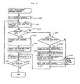
- Fig. 26 is a flowchart illustrating the basic operation of the tape print device.
- the text memory 131 and the like are initialized in S201.
- the tape print device 1 is set into a normal character input mode. Then, it is judged in S202 whether or not any key is manipulated. While no key is manipulated (i.e., S202 is No), control waits input of some key. When some key is manipulated (i.e., S202 is Yes), it is judged in S203 whether or not the inputted key is either one of an alphabetic letter key and a number key.
- character code data corresponding to the inputted key is stored in the text memory 131 in S204.
- a plurality of character code data corresponding to the plural inputted keys are stored in the text memory in the order that the corresponding keys are inputted.
- the display controller DC controls to display the inputted content on the display 22.
- the tape print device 1 When the bar code data input key is inputted (i.e., S206 is Yes), the tape print device 1 is switched from the normal character input mode into a bar code input mode, whereupon a bar code data input process is started in S207, as will be described later.
- the inputted key is not the bar code data input key (S206 is No)
- the inputted key is not the numbering part setting key (S208 is No)
- a process corresponding to the inputted key is executed in S212.
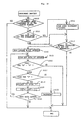
- Fig. 27 is a flowchart showing the bar code data input process program
- Fig. 34 shows the displaying state of the display 22 at the time of the bar code input process.
- the display 22 is first switched into a bar code input screen in S220.
- An initial mark SM is indicated at the left lead position of the bar code input screen.
- An initial code for the bar code is then stored in the bar code buffer 133 in S221.
- S222 and S223 are Yes
- number code data corresponding to the inputted number key is stored in the bar code buffer 133 in S224.
- dot pattern data corresponding to the number code data is read out from the CGROM 123 to be outputted to the display memory 22a.
- the dot pattern representative of the inputted number is displayed on the display 22 at the position indicated by the cursor K.
- the cursor K moves rightwardly in S225.
- the display 22 is then controlled by the display controller DC to display a simplified bar code symbol BS at the right side of the cursor K. The control then returns to S222.
- a check digit number is calculated based on the number code data presently stored in the bar code buffer memory 133 according to a "Modulo 10" system predetermined for the JAN bar code standard format and stored in the ROM 121. A number code data corresponding to the calculated result is also stored in the bar code buffer 133 in S227.
- the bar code buffer 133 now entirely stores the number code data representative of thirteen digit number (effective digit number for the JAN bar code standard format). If the bar code buffer 133 completely stores the number code data of the thirteen digit number (S228 is Yes), an end code is added to the bar code buffer 133 in S229, and the code data stored in the bar code buffer 133 are entirely stored into the text memory 131 in S230. Then, the bar code buffer 133 and the display memory 22a are cleared in S231, and this program ends.
- the initial mark SM, the bar code symbol BS and the cursor K are displayed on the display 22 following the stored text of the normal character string.
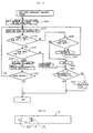
- Fig. 28 is a flowchart showing the numbering part setting process control program.
- Fig. 35 illustrates a display state of the display 22 at the time of setting the numbering part.
- the control waits for manipulation of some key (S242 is No).
- S242 is Yes
- S243 if the manipulated key is the return key (S243 is Yes)
- a lead code and a tail code representing a leading end and a trailing end of the part of the data to be subjected to the numbering process are stored, in S244, into the text memory 131 at positions immediately before and after the initial code and the end code of the bar code data in S244.
- the bar code data is always entirely subjected to the numbering process in the same manner as previously described.
- the inputted key is not the return key (S243 is No) but is the cursor move key (S245 is Yes)
- the warning buzzer sounds off in S248.
- the character code data are capable of being partly subjected to the numbering process.
- a part of the character string represented by the character code data is set for the numbering process, as described below.
- the control waits for input of some key (S251 is No).
- S251 When some key is inputted (S251 is Yes), it is judged in S252 whether or not the inputted key is the cursor move key. If the inputted key is the cursor move key (S252 is Yes), it is judged in S253 whether or not it is possible to move the cursor K. If it is judged that it is impossible to move the cursor K (S253 is NO), the warning buzzer sounds off. If it is judged that it is possible to move the cursor K (S253 is Yes), it is further judged in S254 whether a leading end has already been set for the part to be subjected to the numbering process. If the leading end has already been set (S254 is Yes), the cursor K is moved on the display 22 so that the characters located between the leading end and the position where the cursor K moves to reach are reversely displayed in S255. The program then returns to S251.
- S251 if the inputted key is not the cursor move key (S252 is No), it is judged in S257 whether or not the inputted key is the return key (S257). If the inputted key is not the return key (S257 is No), the warning buzzer sounds off. On the other hand, if the inputted key is the return key (S257 is Yes), it is judged in S258 whether or not the leading end has already been set. If the leading end has not yet been set (S258 is No), the leading end is produced at the position where the cursor K is presently located.
- a lead code is stored in the text memory 131 at a position immediately before the code data corresponding to the character (letter or number) presently indicated by the cursor K in S260.
- the leading end of the part of the character string to be subjected to the numbering process is set. Then, the control returns to S251 to set the trailing end of the part for the numbering process.
- the trailing end is produced at the position where the cursor K is presently located. Then, a tail code is stored in the text memory 131 at a position immediately after the code data corresponding to the character (letter or number) presently indicated by the cursor K in S259.
- the part of the character string to be subjected to the numbering process is set between the lead end and the trail end, and the numbering part setting program 122a ends.
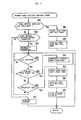
- Fig. 29 is a flowchart of the print process program 122e.
- Fig. 30 is a flowchart of the target number setting program
- Fig. 36 illustrates a displaying state of the display 22 at the time of the target number setting process.
- the display 22 is switched into a screen shown in Fig. 36 in S280.
- the control then waits for the input of the numeric character key (S281 is No). If the numeric character key is inputted (S281 is Yes), the target number, up to which the numbering processes are desired to be repeatedly performed, is set as the inputted number, in S282. When the return key is depressed (S283 is Yes), the target number is finally set, and the program ends. On the other hand, if a key other than the return key is inputted (S283 is No), the warning buzzer sounds off in S284, and the program ends.
- the target number setting program 122g ends in S271 of Fig. 29, the set target number is set in the count memory as a count value M in S272. Afterwardly, an image development process is executed in S273 for developing the text data in the text memory 131 into the print buffer 134.
- Fig. 31 is a flowchart of the image development process control program.
- a leading address in the text memory 131 is set to the image pointer value IP in S290. Then, the code data stored at the address indicated by the image point value IP is read out in S291. Then, it is judged in S292 whether or not the read out code data is a normal character code. If the read out code data is a normal character code (S292 is Yes), a magnification rate is calculated in accordance with the set character size. An outline data stored in the ROM 24 and corresponding to the read out code data is subjected to a magnification process with the use of the calculated magnification rate.
- the magnified outline data is processed into dot pattern data (print data) in S293 and stored in the print buffer 134 in S294. Then, the image pointer value IP is incremented by one in S295. Then, it is judged in S296 whether or not any text data remains unprocessed in the text memory 131. If some text data remains unprocessed in the text memory 131 (S296 is Yes), the process returns to S291. On the other hand, if no text data remains unprocessed in the text memory 131 (S296 is No), the image development process program ends.
- the code data indicated by the image point value IP and read out from the text memory 131 in S291 is not a normal character code (S292 is No)
- S299 thus read out data characters are then converted into bar code modular data of the bar code standard format (for example, JAN) through the bar code data conversion process control program 122f. Then, dot pattern data of the bar code is produced based on the bar code modular data so that the obtained bar code symbol may have a set size.
- dot pattern data for the bar code are stored in the print buffer 134 in S300.
- the address of the text memory at which the end code is stored is set to the data pointer DP in S301, and then, the program proceeds to S295.
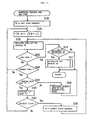
- Fig. 32 is a flowchart of the increment process control program 122b for the code data of the normal characters (letters and/or numbers).
- the increment process control it is first judged in S310 whether or not the increment operation has been performed up to the set target number. If the increment operation has been completed up to the set target number (S310 is Yes), the increment process control program 122b ends. On the other hand, if the increment operation has not yet been performed up to the set target number (S310 is No), it is judged in S311 whether or not the lead code is stored at the bar code data in the text memory 131. If the lead code is stored at the bar code data in the text memory 131 (S311 is Yes), the increment process 122c for the bar code data is performed in S312. On the other hand, if no lead code is stored at the bar code data in the text memory and therefore no part of the bar code data is set to be subjected to the numbering process (S311 is No), the program proceeds to S313.
- Fig. 33 is a flowchart of the increment process control program 122c for the bar code data.
- an address in the text memory 131, at which the code data of the numerical character-at -the lowest digit of the twelve digit number of the data characters for the bar code data is stored, is set to the data pointer value DP in S330.
- the code data of the numerical character stored at the address indicated by the data pointer value DP is read out from the text memory in S331.
- the read out code data is the code data for the number "9" (S333 is Yes)
- the code data indicated by the data pointer value DP is replaced with the code data for the number "0" in S334.
- the data pointer value DP is incremented by one (1) in S335.
- the code data read out in S332 is not any of the code data for the numbers "0" to "9" (S332 is No)
- S313 it is judged whether any part of the normal character string stored in the text memory 131 is set to be subjected to the numbering process. If the lead code and the tail code are stored in the text memory to set some part of the normal character string for the numbering process (S313 is Yes), the address in the text memory, at which the lowest digit or the tailing end of the part of the character string set for the numbering process is stored, is set to the data pointer value DP in S314. Then, the code data stored at the address indicated by the data pointer value DP is read out from the text memory in S315.
- the read out code data represents the number "9" (S317 is Yes)
- the code data indicated by the data pointer value DP is replaced with a code data representative of the number "0" in S318.
- the data pointer value DP is incremented by one in S319.
- the print tape thus printed with the content which has been stored in the text memory is fed out by the predetermined feed amount by the tape feed motor, and is cut off with the cutter into a label.
- numeric character keys are operated to execute the steps S202 through S204 of Fig. 26 to input the number string "0 1 2".
- the bar code input key, numeric character keys, and the return key are operated to execute the processes S202, S203, S206 and S207 to input the character code data "1 2 3 4 5 6 7 8 9 0 1 2 8" for a bar code into the bar code buffer 133.
- the first twelve digit numbers "1 2 3 4 5 6 7 8 9 0 1 2" are inputted through the manipulation of the numeric character keys, but the thirteenth digit number "8" is calculated in the step S227 in Fig. 27 and inputted as a check digit number for the twelve digit numbers "1 2 3 4 5 6 7 8 9 0 1 2" through the well-known Modulo 10 method predetermined for the JAN bar code standard format.
- the numbering part setting key, the cursor move key, and the return key are manipulated to execute the steps S202, S203, S206, S208 and S209 so as to set the number string "0 1 2" and the bar code data to be subjected to the numbering process.
- the print key is manipulated, the print process of S211 is performed.
- the target number up to which the numbering process should be repeatedly performed is set to "9" in the step S271 of Fig. 29.
- the character string and the bar code data are developed into dot pattern data, which are then stored in the print buffer 134.
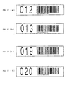
- the dot pattern data are printed on the print tape, and the printed result shown in Fig. 37(a) is obtained.
- step S275 the increment process is attained.
- the normal character string "0 1 2” is incremented into “0 1 3”
- the bar code data is incremented into "1 2 3 4 5 6 7 8 9 0 1 3 5".
- the twelve digit number "1 2 3 4 5 6 7 8 9 0 1 2” is incremented into the twelve digit number "1 2 3 4 5 6 7 8 9 0 1 3”.
- the thirteenth digit number "5" is the check digit data for the twelve digit number "1 2 3 4 5 6 7 8 9 0 1 3".
- incremented data are then printed on the tape, as shown in Fig. 37(b).
- the increment process are repeatedly performed. After when the character string "0 1 9”, and the bar code data "1 2 3 4 5 6 7 8 9 0 1 9 7" are printed, the character string data is further incremented through the steps S315 - S321 of Fig. 32 into a character string "0 2 0”, and the bar code data is further incremented through the steps S331 - S342 of Fig. 33 into a bar code data "1 2 3 4 5 6 7 8 9 0 2 0 3". Then, the thus incremented data are printed on the tape, as shown in Fig. 37(d).
- the normal character string and the bar code are incremented simultaneously according to the character string increment process program 122b and the bar code increment process program 122c, respectively, while they are printed onto the tape through the image development process program 122d and the print process program 122e. Accordingly, both the normal character string and the bar code are printed on the tape while being incremented simultaneously.
- a plurality of tape labels are easily obtained, on which a plurality of incremented pairs of bar codes and corresponding normal character strings are printed.
- Each label thus printed with the bar code and the normal character string representing the content of the bar code can be read out by both the bar code reader and the operator. Therefore, attaching the labels, as identification labels, onto a plurality of articles can enhance the efficiency of management control of the articles.
- the present invention can be applied to a variety of tape printers that include a keyboard, display, printer, and the like and that are capable of printing bar codes, text, and the like on a tape-like print medium using a numbering function, a bar code print function, and the like.
- the bar code standard format for producing the bar code can be freely selected in the present invention.
- the tape print device of the present invention is provided with the print tape producing unit and the incrementing unit.
- bar code data that includes a common character string and a countable character string can print corresponding serially-incremented bar codes. More specifically, the countable character string is serially incremented and recorded. Bar codes reflecting the incrementation are printed. Incrementing the countable character string and printing the bar codes accordingly are repeated so that a plurality of numbered bar codes can be easily printed on tapes to form labels.
- the tape print device of the present invention may further include the numbering setting unit for setting a character string to be subjected to the numbering processes.
- the numbering setting unit receives a predetermined setting command from the input unit and stores data for indicating start and stop positions of bar code data, which includes a common character string and a countable character string. Therefore, starts and stops need not be individually set each time bar code data is set. Processes for setting bar code data as the numbering character string are therefore simplified.
- the incrementing unit calculates the check digit data relating to the common character string and the countable character string. Also, the bar code data produced by incrementing the calculated check digit data is stored in the data memory means. Therefore, even if the bar code standard has check digit data, numbering processes can be reliably performed on the bar code data. Regardless of whether check digit is present or absent, numbering processes can be performed on the bar code data. Therefore all-purposeness of the bar code can be increased.
Landscapes
- Physics & Mathematics (AREA)
- General Physics & Mathematics (AREA)
- Engineering & Computer Science (AREA)
- Theoretical Computer Science (AREA)
- Printers Characterized By Their Purpose (AREA)
- Record Information Processing For Printing (AREA)
Claims (12)
- Banddruckvorrichtung zum Drucken von Strichcodes auf ein Druckband, wobei die Vorrichtung aufweist:ein Eingabemittel (A) zum Eingeben von Daten, die anzeigend für einen Strichcode sind, von dem gewünscht wird, daß er auf ein Band gedruckt wird;ein Datenspeichermittel (B) zum zeitweiligen Speichern der eingegebenen Daten;ein Inkrementierungsmittel (F) zum seriellen Inkrementieren von mindestens einem Teil der Daten, die in dem Datenspeichermittel gespeichert sind, mindestens ein Mal entsprechend einer vorbestimmten Reihenfolge, um dadurch mindestens einen inkrementierten Wert zu erzeugen, der anzeigend für mindestens einen inkrementierten Strichcode ist, wobei der derart erzeugte mindestens eine inkrementierte Wert in dem Datenspeichermittel gespeichert wird;ein Drucktdatenerzeugungsmittel (E) zum Erzeugen von Druckdaten für den gewünschten Strichcode und den mindestens einen inkrementierten Strichcode, basierend auf den Daten, die in dem Datenspeichermittel gespeichert sind; undein Druckmittel (D) zum Empfangen der Druckdaten und zum Drucken von Bildern des gewünschten Strickcodes und des mindestens einen inkrementierten Strichcodes auf ein Druckband; undein Zielzahleinstellmittel zum Einstellen einer Zielzahl, bis zu der von dem Inkrementierungsmittel gewünscht wird, daß es mindestens einen Teil der Daten, die in dem Datenspeichermittel gespeichert sind, seriell inkrementiert,bei der das Inkrementierungsmittel (F) mindestens einen Teil der Daten, die in dem Datenspeichermittel gespeichert sind, so oft, wie es der Zielzahl entspricht, seriell inkrementiert, um dadurch eine der Zielzahl entsprechende Anzahl von seriell-inkrementierten Daten, die anzeigend für eine der Zielzahl entsprechende Anzahl von seriell-inkrementierten Strichcodes sind, zu erzeugen; undbei der das Inkrementiermittel (F) ein Mittel zum Ersetzen der Daten, die momentan in dem Datenspeichermittel gespeichert sind, mit den derart erzeugten inkrementierten Daten jedes Mal, nachdem das Druckdatenerzeugungsmittel (E) das Erzeugen von Druckdaten basierend auf dem momentan in dem Datenspeichermittel gespeicherten Daten vervollständigt hat, aufweist;
bei derdas Eingabemittel (A) ein Strichcodemoduseingabemittel zum Eingeben von Daten einer ersten Zeichenfolge, die aus einer Mehrzahl von ersten Zeichen gebildet ist, die für einen Strichcode anzeigend sind, von dem gewünscht wird, daß er auf ein Band gedruckt wird, aufweist, wobei die erste Zeichenfolge einen gemeinsamen ersten Zeichenfolgenteil und einen zählbaren ersten Zeichenfolgenteil aufweist, wobei das Datenspeichermittel zeitweilig die eingegebenen Daten der ersten Zeichenfolge speichert;das Eingabemittel weiter ein Zeichenmoduseingabemittel (3) zum Eingeben von Daten einer zweiten Zeichenfolge, die aus einer Mehrzahl von zweiten Zeichen, von denen gewünscht wird, daß sie auf ein Band zusammen mit dem gewünschten Strichcode gedruckt werden, gebildet ist, aufweist, wobei die zweite Zeichenfolge einen gemeinsamen zweiten Zeichenfolgenteil und ein zählbaren zweiten Zeichenfolgenteil aufweist, wobei das Datenspeichermittel zeitweilig ein Paar der eingegebenen Daten der zweiten Zeichenfolge und der eingegebenen Daten der ersten Zeichenfolge für den gewünschten Strichcode speichert, und bei derdas Inkrementierungsmittel (F) seriell jede der Daten des zählbaren ersten Zeichenfolgenteils der ersten Zeichenfolge und der Daten der zählbaren zweiten Zeichenfolge der zweiten Zeichenfolge, die beide in dem Datenspeichermittel gespeichert sind, entsprechend der vorbestimmten Reihenfolge inkrementiert, um dadurch ein Paar von Daten aus mindestens einer inkrementierten ersten Zeichenfolge und Daten aus mindestens einer inkrementierten zweiten Zeichenfolge zu erzeugen, wobei ein Paar der derart erzeugten Daten von mindestens einer inkrementierten ersten Zeichenfolge und mindestens einer inkrementierten zweiten Zeichenfolge in dem Datenspeichermittel (B) gespeichert wird, das Druckdatenerzeugungsmittel (E) Druckdaten für das Paar aus dem gewünschten Strichcode und der gewünschten zweiten Zeichenfolge und das mindestens eine Paar aus dem inkrementierten Strichcode und der inkrementierten zweiten Zeichenfolge, basierend auf den Daten, die in dem Datenspeichermittel gespeichert sind, erzeugt, und das Druckmittel (D) die Druckdaten empfängt und Druckbilder des Paares aus dem gewünschten Strichcode und der gewünschten zweiten Zeichenfolge und dem mindestens einen Paar aus dem inkrementierten Strichcode und der inkrementierten zweiten Zeichenfolge auf ein Druckband druckt. - Banddruckvorrichtung nach Anspruch 1, bei der
das Inkrementierungsmittel (F) seriell Daten des zählbaren ersten Zeichenfolgenteils der ersten Zeichenfolge, die in dem Datenspeichermittel (B) gespeichert ist, entsprechend der vorbestimmten Reihenfolge inkrementiert, um dadurch Daten von mindestens einer inkrementierten ersten Zeichenfolge zu erzeugen, die anzeigend für mindestens einen inkrementierten Strichcode sind, wobei die derart erzeugten Daten der mindestens einen inkrementierten ersten Zeichenfolge in dem Datenspeichermittel (B) gespeichert werden. - Banddruckvorrichtung nach Anspruch 2, die weiter
ein Checkstellendatenberechnungsmittel (F) zum Berechnen eines Checkstellenwertes basierend auf dem gemeinsamen ersten Zeichenfolgenteil und dem zählbaren ersten Zeichenfolgenteil der eingegebenen Daten der ersten Zeichenfolge aufweist, wobei der berechnete Checkstellenwert in dem Datenspeichermittel zusammen mit den eingegebenen Daten der ersten Zeichenfolge gespeichert wird, das Checkstellendatenberechnungsmittel weiter einen anderen Checkstellenwert, der sich auf den gemeinsamen ersten Zeichenfolgenteil und den inkrementierten zählbaren ersten Zeichenfolgenteil von jeder der mindestens einen inkrementierten ersten Zeichenfolge bezieht, berechnet, wobei der derart berechnete andere Checkstellenwert in dem Datenspeichermittel zusammen mit der entsprechenden inkrementierten ersten Zahlenfolge gespeichert wird. - Banddruckvorrichtung nach Anspruch 1, bei der
das Inkrementierungsmittel (7) ein Strichcode/Zeichen-Inkrementierungsmittel zum wiederholten Inkrementieren des zählbaren ersten Zeichenfolgenteils und des zählbaren zweiten Zeichenfolgenteils eines Paares von Daten aus der ersten Zeichenfolge und der zweiten Zeichenfolge, die momentan in dem Datenspeichermittel (B) gespeichert werden, aufweist, um dadurch ein Paar von inkrementierten Daten, die anzeigend für eine inkrementierte erste Zeichenfolge und eine inkrementierte zweite Zeichenfolge sind, zu erzeugen und das Paar von Daten, die momentan in dem Datenspeichermittel gespeichert sind, mit dem derart produzierten Paar von inkrementierten Daten jedes Mal zu ersetzen, nachdem das Druckdatenerzeugungsmittel das Erzeugen von Druckdaten basierend auf dem Paar der momentan in dem Datenspeichermittel gespeicherten Daten vervollständigt hat. - Banddruckvorrichtung nach einem der Ansprüche 2 bis 4, bei der
der gemeinsame erste Zeichenfolgenteil aus einer Buchstabenfolge konstruiert ist und der zählbare erste Zeichenfolgenteil aus einer Zahlenfolge konstruiert ist. - Banddruckvorrichtung nach einem der Ansprüche 4 bis 5, die weiter
ein Einstellmittel für den zählbaren zweiten Zeichenfolgenteil zum Einstellen von Daten, die anzeigend für Start- und Stopppositionen des zählbaren zweiten Zeichenfolgenteils der zweiten Zeichenfolge sind, die in dem Datenspeichermittel (B) gespeichert ist, aufweist, wobei die Daten für die Start- und Stopppositionen in dem Datenspeichermittel gespeichert werden, und das Inkrementierungsmittel (F) den zählbaren zweiten Zeichenfolgenteil inkrementiert, der in Übereinstimmung mit den gespeicherten Daten für die Start- und Stopppositionen bestimmt ist. - Banddruckvorrichtung nach einem der Ansprüche 1 bis 6, die weiter
ein Anzeigemittel (C) zum Anzeigen eines Bildes zum Anzeigen dessen, daß das Eingabemittel (A) Daten des gewünschten Strichcodes eingibt, aufweist. - Banddruckvorrichtung nach einem der Ansprüche 1 bis 7, die aufweist:ein Eingabemittel (A) zum Eingeben verschiedener Befehle, wobei die Daten, die anzeigend für einen Strichcode sind, Daten einer gemeinsamen Zeichenfolge und einer zählbaren Zeichenfolge enthalten;ein Anzeigemittel (22) zum Empfangen der Daten, die in dem Datenspeichermittel (C) gespeichert sind, und zum Anzeigen der Daten;das Druckdatenerzeugungsmittel (E) zum Empfangen der Daten von dem Datenspeichermittel und zum Erzeugen von Punktbilddaten zum Drucken;das Druckmittel (D) zum Empfangen der Punktbilddaten und zum Drucken eines Punktbildes auf ein Druckband;das Inkrementierungsmittel (F) zum Inkrementieren der Daten der zählbaren Zeichenfolge jedes Mal, wenn das Druckmittel einen Druckbetrieb zum Drucken des Punktbildes basierend auf den Daten von dem Datenspeichermittel ausführt, wobei das Inkrementierungsmittel die Daten der zählbaren Zeichenfolge, die in dem Speichermittel gespeichert sind, mit den Daten der inkrementierten zählbaren Zeichenfolge aktualisiert, wobei das Inkrementierungsmittel wiederholt die zählbare Zeichenfolge der Daten, die in dem Datenspeichermittel gespeichert sind, inkrementiert, während das Druckdatenerzeugungsmittel wiederholt Punktbilddaten für die Daten, die in dem Datenspeichermittel gespeichert sind, erzeugt zum Bringen des Druckmittels zum wiederholten Drucken der Daten auf ein Band, um dadurch das Druckband mit einer Mehrzahl von Strichcodes zu bedrucken, wobei ihre zählbaren Zeichenfolgen seriell inkrementiert sind.
- Banddruckvorrichtung nach einem der Ansprüche 1 bis 8, die weiter
ein Einstellmittel (G) zum Empfangen eines vorbestimmten Befehls zum Ausführen der Inkrementierungsprozesse und zum Einstellen von Daten zum Anzeigen von Start- und Stopppositionen der Daten des Strichcodes, zwischen denen sowohl die gemeinsame Zeichenfolge als auch die zählbare Zeichenfolge befindlich sind, aufweist, wobei die Daten für die Start- und Stopppositionen in dem Datenspeichermittel gespeichert werden. - Banddruckvorrichtung nach Anspruch 2, bei der
das Inkrementierungsmittel (F) ein Checkstellendatenberechnungsmittel zum Berechnen eines Checkstellenwertes, der sich auf die gemeinsame Zeichenfolge und die inkrementierte zählbare Zeichenfolge bezieht, aufweist, wobei der derart berechnete Checkstellenwert für die inkrementierte zählbare Zeichenfolge und die gemeinsame Zeichenfolge in dem Datenspeichermittel zusammen mit den Daten für die gemeinsame Zeichenfolge und die inkrementierte zählbare Zeichenfolge gespeichert wird. - Banddruckvorrichtung nach Anspruch 1, die aufweist:das Eingabemittel (A) zum Eingeben von Daten einer Zeichenfolge, die anzeigend für einen Strichcode ist, von dem gewünscht wird, daß er auf ein Druckband gedruckt wird, und von Daten einer normalen Zeichenfolge, von der gewünscht wird, daß sie auf das Druckband zusammen mit dem Strichcode gedruckt wird, und von verschiedenen Befehlen;ein Strichcodedatenumwandlungsmittel zum Umwandeln der Daten der eingegebenen Zeichenfolge in Strichcodedaten;ein Anzeigemittel (C) zum Anzeigen der eingegebenen Referenzzeichenfolge und der Strichcodedaten, die durch die Strichcodedatenumwandlungseinheit aus der eingegebenen Zeichenfolge umgewandelt worden sind;das Datenspeichermittel (B) zum Speichern der Daten der eingegebenen Referenzzeichenfolge und der Strichcodedaten, die durch die Strichcodedatenumwandlungseinheit aus der eingegebenen Zeichenfolge umgewandelt worden sind;ein Druckdatenumwandlungsmittel zum Umwandeln der Daten der Referenzzeichenfolge und der Strichcodedaten, die in der Datenspeichereinheit gespeichert sind, in Punktmusterdaten zum Drukken;ein Druckdatenspeichermittel zum Speichern der Punktmusterdaten;das Zielzahleinstellmittel zum Einstellen einer Zielzahl, bis zu der sowohl für die Referenzzeichenfolgendaten als auch die Strichcodedaten gewünscht wird, daß sie seriell inkrementiert werden;ein Numerierungsteileinstellmittel (G) zum Einstellen von mindestens einem Teil von jeweils den Referenzzeichenfolgendaten und den Strichcodedaten derart, daß für sie eine serielle Inkrementierung erwünscht ist;ein Strichcodeinkrementierungsmittel zum seriellen Inkrementieren der Strichcodedaten, die momentan in der Datenspeichereinheit gespeichert sind, und zum Ersetzen der Strichcodedaten durch die inkrementierten Strichcodedaten, wiederholt von einer anfänglichen Zahl bis zu der Zielzahl von Malen, die durch die Zielzahleinstelleinheit eingestellt ist;eine Referenzzeichenfolgeninkrementierungsmittel zu seriellen Inkrementieren von mindestens einem Teil der Daten der Referenzzeichenfolge, die in dem Datenspeichermittel gespeichert ist, und zum Ersetzen der Referenzzeichenfolgendaten mit den inkrementierten Referenzzeichenfolgendaten, wiederholt von der anfänglichen Zahl bis zu der Zielzahl von Malen, die durch die Zielzahleinstelleinheit eingestellt ist; unddas Druckmittel (D), das durch die Punktmusterdaten, die in der Druckdatenspeichereinheit gespeichert sind, zum wiederholten Drucken von sowohl der Referenzzeichenfolge als auch den Strichcodesymbolen bis zu der eingestellten Zielanzahl von Malen gesteuert wird.
- Banddruckvorrichtung nach einem der Ansprüche 1 bis 11, bei der
die Daten, die anzeigend für den Strichcode sind, Daten einer Buchstabenfolge und einer Zahlenfolge enthalten,
bei der das Inkrementierungsmittel (F) ein Beurteilungsmittel zum Beurteilen, ob die jeweiligen Daten, die anzeigend für den Strichcode sind, Daten eines Buchstabens oder einer Zahl sind, wobei das Inkrementierungsmittel nur die Daten der Zahl, die durch das Beurteilungsmittel beurteilt worden ist, inkrementiert.
Applications Claiming Priority (6)
| Application Number | Priority Date | Filing Date | Title |
|---|---|---|---|
| JP31913393 | 1993-11-24 | ||
| JP31913393A JP3237979B2 (ja) | 1993-11-24 | 1993-11-24 | テープ印刷装置 |
| JP319133/93 | 1993-11-24 | ||
| JP34958393A JP3516212B2 (ja) | 1993-12-27 | 1993-12-27 | 印刷装置 |
| JP349583/93 | 1993-12-27 | ||
| JP34958393 | 1993-12-27 |
Publications (4)
| Publication Number | Publication Date |
|---|---|
| EP0654747A2 EP0654747A2 (de) | 1995-05-24 |
| EP0654747A3 EP0654747A3 (de) | 1997-11-12 |
| EP0654747B1 EP0654747B1 (de) | 2000-09-20 |
| EP0654747B2 true EP0654747B2 (de) | 2003-11-05 |
Family
ID=26569612
Family Applications (1)
| Application Number | Title | Priority Date | Filing Date |
|---|---|---|---|
| EP94118529A Expired - Lifetime EP0654747B2 (de) | 1993-11-24 | 1994-11-24 | Banddrucker |
Country Status (3)
| Country | Link |
|---|---|
| US (1) | US5496117A (de) |
| EP (1) | EP0654747B2 (de) |
| DE (1) | DE69425947T3 (de) |
Families Citing this family (22)
| Publication number | Priority date | Publication date | Assignee | Title |
|---|---|---|---|---|
| US6766953B1 (en) * | 1992-05-01 | 2004-07-27 | Hewlett-Packard Development Company, L.P. | Tape indicia on clear film media |
| JP3090002B2 (ja) * | 1995-09-12 | 2000-09-18 | マックス株式会社 | プリンタ装置 |
| EP0768611A3 (de) * | 1995-10-09 | 2004-05-26 | Max Co., Ltd. | Streifendrucker |
| DE29602534U1 (de) * | 1996-02-14 | 1996-04-18 | Esselte N.V., St. Niklaas | Banddruckgerät mit der Fähigkeit zum Drucken von Strichcodes |
| EP0858027A3 (de) * | 1997-02-10 | 2001-10-04 | Seiko Epson Corporation | Aufzeichnungsgerät und Aufzeichnungsverfahren |
| US6098892A (en) * | 1998-05-27 | 2000-08-08 | Peoples, Jr.; Max J. | Device for conversion from a pharmaceutical identification number to a standardized number and method for doing the same |
| US6192165B1 (en) | 1997-12-30 | 2001-02-20 | Imagetag, Inc. | Apparatus and method for digital filing |
| US6744936B2 (en) | 1997-12-30 | 2004-06-01 | Imagetag, Inc. | Apparatus and method for simultaneously managing paper-based documents and digital images of the same |
| US6674924B2 (en) | 1997-12-30 | 2004-01-06 | Steven F. Wright | Apparatus and method for dynamically routing documents using dynamic control documents and data streams |
| US6427032B1 (en) | 1997-12-30 | 2002-07-30 | Imagetag, Inc. | Apparatus and method for digital filing |
| JP3777862B2 (ja) * | 1999-03-30 | 2006-05-24 | セイコーエプソン株式会社 | 画像印刷方法およびその装置 |
| US20040131409A1 (en) * | 2001-03-14 | 2004-07-08 | Sergej Toedtli | Method for providing identification codes for articles |
| FR2826758B1 (fr) | 2001-06-27 | 2003-10-24 | Frederic Jouvin | Procede de suivi d'un envoi, dispositif pour la mise en oeuvre du procede et appareil d'impression |
| EP1451733A1 (de) * | 2001-11-06 | 2004-09-01 | Orell Füssli Security Documents AG | Verfahren und vorrichtung zur überwachung von warenflüssen |
| JP4407340B2 (ja) | 2004-03-26 | 2010-02-03 | ブラザー工業株式会社 | テープ印字装置 |
| US8339652B2 (en) | 2008-03-12 | 2012-12-25 | Seiko Epson Corporation | Label creating apparatus, method for controlling label creating apparatus and computer program |
| JP2011011450A (ja) * | 2009-07-02 | 2011-01-20 | Seiko Epson Corp | テープ印刷装置及びその制御方法 |
| JP5444998B2 (ja) * | 2009-09-28 | 2014-03-19 | ブラザー工業株式会社 | 印刷装置及び印刷装置制御方法 |
| WO2012148392A1 (en) * | 2011-04-27 | 2012-11-01 | Hewlett-Packard Development Company, L.P. | Dual deterrent incremental information object |
| JP5750461B2 (ja) * | 2012-01-26 | 2015-07-22 | 京セラドキュメントソリューションズ株式会社 | 操作装置、画像形成装置及び画像形成装置システム |
| JP2013161273A (ja) | 2012-02-06 | 2013-08-19 | Seiko Epson Corp | 制御装置、印刷システム、印刷装置、印刷制御方法およびプログラム |
| CN111532034A (zh) * | 2020-05-26 | 2020-08-14 | 云南岭东印刷包装有限公司 | 一种印刷品二维码喷码及检测一体化装置 |
Citations (3)
| Publication number | Priority date | Publication date | Assignee | Title |
|---|---|---|---|---|
| US4407692A (en) † | 1981-05-29 | 1983-10-04 | Monarch Marking Systems, Inc. | Hand-held electrically selectable labeler |
| EP0422648A2 (de) † | 1989-10-13 | 1991-04-17 | Kabushiki Kaisha TEC | Etikettendrucker |
| EP0268771B1 (de) † | 1986-10-17 | 1992-03-04 | Kabushiki Kaisha Sato | Datenspeichergerät für tragbaren Etikettendrucker |
Family Cites Families (14)
| Publication number | Priority date | Publication date | Assignee | Title |
|---|---|---|---|---|
| US4641347A (en) * | 1983-07-18 | 1987-02-03 | Pitney Bowes Inc. | System for printing encrypted messages with a character generator and bar-code representation |
| US4829568A (en) * | 1983-07-21 | 1989-05-09 | Pitney Bowes | System for the printing and reading of encrypted messages |
| JPS61883A (ja) * | 1984-06-14 | 1986-01-06 | Mitsubishi Electric Corp | 印字装置 |
| JPH085227B2 (ja) * | 1984-11-29 | 1996-01-24 | 株式会社サト− | サ−マル印字カセツト及びサ−マルプリンタ− |
| JPS61244734A (ja) * | 1985-04-19 | 1986-10-31 | 株式会社 サト− | サ−マルラベルプリンタ |
| US4807177A (en) * | 1986-06-06 | 1989-02-21 | Ward Richard J | Multiple format hand held label printer |
| US5184900A (en) * | 1986-10-14 | 1993-02-09 | Bryce Office Systems, Inc. | Envelope addressing system adapted to simultaneously print addresses and bar codes |
| US5025397A (en) * | 1988-08-24 | 1991-06-18 | Tokyo Electric Co., Ltd. | Label printer |
| US5188469A (en) * | 1988-10-14 | 1993-02-23 | Brother Kogyo Kabushiki Kaisha | Tape feed cassette with tape cutter and guide |
| JPH02106555A (ja) * | 1988-10-14 | 1990-04-18 | Brother Ind Ltd | テープ収納カセット |
| JPH02192968A (ja) * | 1989-01-20 | 1990-07-30 | Tokyo Electric Co Ltd | バーコードプリンタ |
| US5188464A (en) * | 1991-12-10 | 1993-02-23 | Aaron Nancy A | Hand-held bar code printer for envelopes and labels |
| JP2974038B2 (ja) * | 1991-12-28 | 1999-11-08 | ブラザー工業株式会社 | バーコード記録装置 |
| JP2985910B2 (ja) * | 1992-01-08 | 1999-12-06 | ブラザー工業株式会社 | 印字装置 |
-
1994
- 1994-11-24 EP EP94118529A patent/EP0654747B2/de not_active Expired - Lifetime
- 1994-11-24 DE DE69425947T patent/DE69425947T3/de not_active Expired - Lifetime
- 1994-11-25 US US08/348,111 patent/US5496117A/en not_active Expired - Lifetime
Patent Citations (3)
| Publication number | Priority date | Publication date | Assignee | Title |
|---|---|---|---|---|
| US4407692A (en) † | 1981-05-29 | 1983-10-04 | Monarch Marking Systems, Inc. | Hand-held electrically selectable labeler |
| EP0268771B1 (de) † | 1986-10-17 | 1992-03-04 | Kabushiki Kaisha Sato | Datenspeichergerät für tragbaren Etikettendrucker |
| EP0422648A2 (de) † | 1989-10-13 | 1991-04-17 | Kabushiki Kaisha TEC | Etikettendrucker |
Non-Patent Citations (2)
| Title |
|---|
| User's Guide of DYMO 6000 Electronic Labelmaker, Esselte Dymo 1992 † |
| User's Guide of Merlin Express ELITE 2000 and ELITE, 2nd Edition May 1991 † |
Also Published As
| Publication number | Publication date |
|---|---|
| EP0654747B1 (de) | 2000-09-20 |
| EP0654747A3 (de) | 1997-11-12 |
| DE69425947D1 (de) | 2000-10-26 |
| EP0654747A2 (de) | 1995-05-24 |
| DE69425947T2 (de) | 2001-03-01 |
| DE69425947T3 (de) | 2004-05-13 |
| US5496117A (en) | 1996-03-05 |
Similar Documents
| Publication | Publication Date | Title |
|---|---|---|
| EP0654747B2 (de) | Banddrucker | |
| US5584591A (en) | Tape printer | |
| EP0577247B1 (de) | Streifendrucker | |
| US5609424A (en) | Tape-shaped label producing device having input instructing messages | |
| EP0661656B1 (de) | Streifendrucker | |
| EP0862517B1 (de) | Streifendrucker | |
| US5993086A (en) | Character printing apparatus having judging means | |
| JP3587181B2 (ja) | テープ状ラベル作成装置 | |
| JP2998829B2 (ja) | テープ状ラベル作成装置 | |
| JPH07210138A (ja) | 文書処理装置 | |
| JP3445661B2 (ja) | テープ状ラベル作成装置 | |
| EP0660248B1 (de) | Textverarbeitungsgerät | |
| JP3892055B2 (ja) | テープ状ラベル作成装置 | |
| JP3237979B2 (ja) | テープ印刷装置 | |
| JP3254653B2 (ja) | テープ印刷装置 | |
| JP3464205B2 (ja) | テープ印刷装置 | |
| JPH07276715A (ja) | 任意行数のブロックを複数印字可能なテープ印字装置 | |
| JPH05342386A (ja) | バーコード印刷装置 | |
| JP3258578B2 (ja) | 記録装置 | |
| JPH08310052A (ja) | テープ状ラベル作成装置 | |
| JPH07132657A (ja) | テープ印刷装置 | |
| JPH0825708A (ja) | テープ状ラベル作成装置 | |
| JPH0999591A (ja) | テープ状ラベル作成装置 | |
| JPH0699637A (ja) | テープ印字装置 | |
| JP2000318232A (ja) | 記録装置 |
Legal Events
| Date | Code | Title | Description |
|---|---|---|---|
| PUAI | Public reference made under article 153(3) epc to a published international application that has entered the european phase |
Free format text: ORIGINAL CODE: 0009012 |
|
| AK | Designated contracting states |
Kind code of ref document: A2 Designated state(s): BE DE FR GB |
|
| PUAL | Search report despatched |
Free format text: ORIGINAL CODE: 0009013 |
|
| AK | Designated contracting states |
Kind code of ref document: A3 Designated state(s): BE DE FR GB |
|
| 17P | Request for examination filed |
Effective date: 19980213 |
|
| 17Q | First examination report despatched |
Effective date: 19980904 |
|
| GRAG | Despatch of communication of intention to grant |
Free format text: ORIGINAL CODE: EPIDOS AGRA |
|
| GRAG | Despatch of communication of intention to grant |
Free format text: ORIGINAL CODE: EPIDOS AGRA |
|
| GRAH | Despatch of communication of intention to grant a patent |
Free format text: ORIGINAL CODE: EPIDOS IGRA |
|
| GRAG | Despatch of communication of intention to grant |
Free format text: ORIGINAL CODE: EPIDOS AGRA |
|
| GRAH | Despatch of communication of intention to grant a patent |
Free format text: ORIGINAL CODE: EPIDOS IGRA |
|
| GRAA | (expected) grant |
Free format text: ORIGINAL CODE: 0009210 |
|
| AK | Designated contracting states |
Kind code of ref document: B1 Designated state(s): BE DE FR GB |
|
| ET | Fr: translation filed | ||
| REF | Corresponds to: |
Ref document number: 69425947 Country of ref document: DE Date of ref document: 20001026 |
|
| PLBQ | Unpublished change to opponent data |
Free format text: ORIGINAL CODE: EPIDOS OPPO |
|
| PLBI | Opposition filed |
Free format text: ORIGINAL CODE: 0009260 |
|
| PLBF | Reply of patent proprietor to notice(s) of opposition |
Free format text: ORIGINAL CODE: EPIDOS OBSO |
|
| 26 | Opposition filed |
Opponent name: ESSELTE N.V. Effective date: 20010619 |
|
| PLBF | Reply of patent proprietor to notice(s) of opposition |
Free format text: ORIGINAL CODE: EPIDOS OBSO |
|
| REG | Reference to a national code |
Ref country code: GB Ref legal event code: IF02 |
|
| PLBF | Reply of patent proprietor to notice(s) of opposition |
Free format text: ORIGINAL CODE: EPIDOS OBSO |
|
| PLAW | Interlocutory decision in opposition |
Free format text: ORIGINAL CODE: EPIDOS IDOP |
|
| PLAW | Interlocutory decision in opposition |
Free format text: ORIGINAL CODE: EPIDOS IDOP |
|
| PUAH | Patent maintained in amended form |
Free format text: ORIGINAL CODE: 0009272 |
|
| STAA | Information on the status of an ep patent application or granted ep patent |
Free format text: STATUS: PATENT MAINTAINED AS AMENDED |
|
| 27A | Patent maintained in amended form |
Effective date: 20031105 |
|
| AK | Designated contracting states |
Kind code of ref document: B2 Designated state(s): BE DE FR GB |
|
| ET3 | Fr: translation filed ** decision concerning opposition | ||
| PGFP | Annual fee paid to national office [announced via postgrant information from national office to epo] |
Ref country code: FR Payment date: 20131025 Year of fee payment: 20 Ref country code: DE Payment date: 20131129 Year of fee payment: 20 Ref country code: GB Payment date: 20131028 Year of fee payment: 20 |
|
| PGFP | Annual fee paid to national office [announced via postgrant information from national office to epo] |
Ref country code: BE Payment date: 20131202 Year of fee payment: 20 |
|
| REG | Reference to a national code |
Ref country code: DE Ref legal event code: R071 Ref document number: 69425947 Country of ref document: DE |
|
| REG | Reference to a national code |
Ref country code: GB Ref legal event code: PE20 Expiry date: 20141123 |
|
| PG25 | Lapsed in a contracting state [announced via postgrant information from national office to epo] |
Ref country code: GB Free format text: LAPSE BECAUSE OF EXPIRATION OF PROTECTION Effective date: 20141123 |