EP0654801B1 - Magnetisches Pulver, Dauermagnet und Herstellungsverfahren - Google Patents
Magnetisches Pulver, Dauermagnet und Herstellungsverfahren Download PDFInfo
- Publication number
- EP0654801B1 EP0654801B1 EP19940114972 EP94114972A EP0654801B1 EP 0654801 B1 EP0654801 B1 EP 0654801B1 EP 19940114972 EP19940114972 EP 19940114972 EP 94114972 A EP94114972 A EP 94114972A EP 0654801 B1 EP0654801 B1 EP 0654801B1
- Authority
- EP
- European Patent Office
- Prior art keywords
- magnetic powder
- powder
- magnetic
- mixed
- bonded magnet
- Prior art date
- Legal status (The legal status is an assumption and is not a legal conclusion. Google has not performed a legal analysis and makes no representation as to the accuracy of the status listed.)
- Expired - Lifetime
Links
- 239000006247 magnetic powder Substances 0.000 title claims description 129
- 238000000034 method Methods 0.000 title description 5
- 230000008569 process Effects 0.000 title description 3
- 239000000843 powder Substances 0.000 claims description 202
- 230000005291 magnetic effect Effects 0.000 claims description 185
- 239000002245 particle Substances 0.000 claims description 54
- 239000011812 mixed powder Substances 0.000 claims description 45
- 239000000203 mixture Substances 0.000 claims description 41
- 238000012856 packing Methods 0.000 claims description 30
- IJGRMHOSHXDMSA-UHFFFAOYSA-N Atomic nitrogen Chemical compound N#N IJGRMHOSHXDMSA-UHFFFAOYSA-N 0.000 claims description 15
- 229910052761 rare earth metal Inorganic materials 0.000 claims description 10
- 230000004907 flux Effects 0.000 claims description 6
- 229910052739 hydrogen Inorganic materials 0.000 claims description 6
- 229910052742 iron Inorganic materials 0.000 claims description 6
- 229910052757 nitrogen Inorganic materials 0.000 claims description 6
- 150000002910 rare earth metals Chemical class 0.000 claims description 6
- UFHFLCQGNIYNRP-UHFFFAOYSA-N Hydrogen Chemical compound [H][H] UFHFLCQGNIYNRP-UHFFFAOYSA-N 0.000 claims description 5
- 239000001257 hydrogen Substances 0.000 claims description 5
- 229910052802 copper Inorganic materials 0.000 claims description 4
- 229910052726 zirconium Inorganic materials 0.000 claims description 4
- 229910000859 α-Fe Inorganic materials 0.000 claims 4
- 229910052723 transition metal Inorganic materials 0.000 claims 2
- 150000003624 transition metals Chemical class 0.000 claims 2
- OKTJSMMVPCPJKN-UHFFFAOYSA-N Carbon Chemical compound [C] OKTJSMMVPCPJKN-UHFFFAOYSA-N 0.000 claims 1
- 229910052799 carbon Inorganic materials 0.000 claims 1
- 239000004615 ingredient Substances 0.000 claims 1
- 230000003993 interaction Effects 0.000 description 54
- 230000005415 magnetization Effects 0.000 description 42
- 230000000052 comparative effect Effects 0.000 description 40
- XEEYBQQBJWHFJM-UHFFFAOYSA-N iron Substances [Fe] XEEYBQQBJWHFJM-UHFFFAOYSA-N 0.000 description 40
- XKRFYHLGVUSROY-UHFFFAOYSA-N Argon Chemical compound [Ar] XKRFYHLGVUSROY-UHFFFAOYSA-N 0.000 description 34
- 239000003822 epoxy resin Substances 0.000 description 30
- 229920000647 polyepoxide Polymers 0.000 description 30
- 238000002844 melting Methods 0.000 description 24
- 230000008018 melting Effects 0.000 description 24
- 239000012298 atmosphere Substances 0.000 description 22
- 238000000748 compression moulding Methods 0.000 description 22
- 239000007789 gas Substances 0.000 description 22
- 238000005266 casting Methods 0.000 description 21
- 238000010438 heat treatment Methods 0.000 description 21
- 238000002156 mixing Methods 0.000 description 21
- 238000000465 moulding Methods 0.000 description 20
- 230000005347 demagnetization Effects 0.000 description 19
- 229910052786 argon Inorganic materials 0.000 description 17
- 239000000243 solution Substances 0.000 description 16
- 150000001875 compounds Chemical class 0.000 description 15
- 230000006698 induction Effects 0.000 description 15
- 239000012300 argon atmosphere Substances 0.000 description 14
- 230000006872 improvement Effects 0.000 description 14
- 239000000463 material Substances 0.000 description 13
- 238000010298 pulverizing process Methods 0.000 description 11
- 239000000696 magnetic material Substances 0.000 description 10
- QGZKDVFQNNGYKY-UHFFFAOYSA-N Ammonia Chemical compound N QGZKDVFQNNGYKY-UHFFFAOYSA-N 0.000 description 9
- 239000012299 nitrogen atmosphere Substances 0.000 description 7
- 238000000265 homogenisation Methods 0.000 description 6
- VZSRBBMJRBPUNF-UHFFFAOYSA-N 2-(2,3-dihydro-1H-inden-2-ylamino)-N-[3-oxo-3-(2,4,6,7-tetrahydrotriazolo[4,5-c]pyridin-5-yl)propyl]pyrimidine-5-carboxamide Chemical compound C1C(CC2=CC=CC=C12)NC1=NC=C(C=N1)C(=O)NCCC(N1CC2=C(CC1)NN=N2)=O VZSRBBMJRBPUNF-UHFFFAOYSA-N 0.000 description 5
- AFCARXCZXQIEQB-UHFFFAOYSA-N N-[3-oxo-3-(2,4,6,7-tetrahydrotriazolo[4,5-c]pyridin-5-yl)propyl]-2-[[3-(trifluoromethoxy)phenyl]methylamino]pyrimidine-5-carboxamide Chemical compound O=C(CCNC(=O)C=1C=NC(=NC=1)NCC1=CC(=CC=C1)OC(F)(F)F)N1CC2=C(CC1)NN=N2 AFCARXCZXQIEQB-UHFFFAOYSA-N 0.000 description 5
- 230000007423 decrease Effects 0.000 description 5
- 230000006866 deterioration Effects 0.000 description 5
- 238000011282 treatment Methods 0.000 description 5
- 229910052772 Samarium Inorganic materials 0.000 description 4
- 229910021529 ammonia Inorganic materials 0.000 description 4
- 239000006185 dispersion Substances 0.000 description 4
- 229910001172 neodymium magnet Inorganic materials 0.000 description 4
- 238000005245 sintering Methods 0.000 description 4
- JHWNWJKBPDFINM-UHFFFAOYSA-N Laurolactam Chemical compound O=C1CCCCCCCCCCCN1 JHWNWJKBPDFINM-UHFFFAOYSA-N 0.000 description 3
- NIPNSKYNPDTRPC-UHFFFAOYSA-N N-[2-oxo-2-(2,4,6,7-tetrahydrotriazolo[4,5-c]pyridin-5-yl)ethyl]-2-[[3-(trifluoromethoxy)phenyl]methylamino]pyrimidine-5-carboxamide Chemical compound O=C(CNC(=O)C=1C=NC(=NC=1)NCC1=CC(=CC=C1)OC(F)(F)F)N1CC2=C(CC1)NN=N2 NIPNSKYNPDTRPC-UHFFFAOYSA-N 0.000 description 3
- 229920000299 Nylon 12 Polymers 0.000 description 3
- 229910045601 alloy Inorganic materials 0.000 description 3
- 239000000956 alloy Substances 0.000 description 3
- 239000002131 composite material Substances 0.000 description 3
- 230000003247 decreasing effect Effects 0.000 description 3
- 229910001873 dinitrogen Inorganic materials 0.000 description 3
- 238000002360 preparation method Methods 0.000 description 3
- 230000032683 aging Effects 0.000 description 2
- 230000008901 benefit Effects 0.000 description 2
- 230000000694 effects Effects 0.000 description 2
- 238000003801 milling Methods 0.000 description 2
- 229910052727 yttrium Inorganic materials 0.000 description 2
- 229910000920 Fe16N2 Inorganic materials 0.000 description 1
- 101000993059 Homo sapiens Hereditary hemochromatosis protein Proteins 0.000 description 1
- 229910052779 Neodymium Inorganic materials 0.000 description 1
- 229910052777 Praseodymium Inorganic materials 0.000 description 1
- QJVKUMXDEUEQLH-UHFFFAOYSA-N [B].[Fe].[Nd] Chemical compound [B].[Fe].[Nd] QJVKUMXDEUEQLH-UHFFFAOYSA-N 0.000 description 1
- 239000006096 absorbing agent Substances 0.000 description 1
- HSFWRNGVRCDJHI-UHFFFAOYSA-N alpha-acetylene Natural products C#C HSFWRNGVRCDJHI-UHFFFAOYSA-N 0.000 description 1
- 239000003963 antioxidant agent Substances 0.000 description 1
- 230000003078 antioxidant effect Effects 0.000 description 1
- 229910052804 chromium Inorganic materials 0.000 description 1
- 230000001427 coherent effect Effects 0.000 description 1
- 230000008878 coupling Effects 0.000 description 1
- 238000010168 coupling process Methods 0.000 description 1
- 238000005859 coupling reaction Methods 0.000 description 1
- 230000001419 dependent effect Effects 0.000 description 1
- 238000011038 discontinuous diafiltration by volume reduction Methods 0.000 description 1
- 125000002534 ethynyl group Chemical group [H]C#C* 0.000 description 1
- 239000003302 ferromagnetic material Substances 0.000 description 1
- 238000009472 formulation Methods 0.000 description 1
- 229910052735 hafnium Inorganic materials 0.000 description 1
- 238000002347 injection Methods 0.000 description 1
- 239000007924 injection Substances 0.000 description 1
- 229910001337 iron nitride Inorganic materials 0.000 description 1
- JEIPFZHSYJVQDO-UHFFFAOYSA-N iron(III) oxide Inorganic materials O=[Fe]O[Fe]=O JEIPFZHSYJVQDO-UHFFFAOYSA-N 0.000 description 1
- 239000007788 liquid Substances 0.000 description 1
- 239000006249 magnetic particle Substances 0.000 description 1
- 229910052748 manganese Inorganic materials 0.000 description 1
- 238000004519 manufacturing process Methods 0.000 description 1
- 238000005551 mechanical alloying Methods 0.000 description 1
- 229910052758 niobium Inorganic materials 0.000 description 1
- 238000004663 powder metallurgy Methods 0.000 description 1
- 238000010791 quenching Methods 0.000 description 1
- 230000000171 quenching effect Effects 0.000 description 1
- 230000009467 reduction Effects 0.000 description 1
- 229920005989 resin Polymers 0.000 description 1
- 239000011347 resin Substances 0.000 description 1
- 239000011369 resultant mixture Substances 0.000 description 1
- 229920002545 silicone oil Polymers 0.000 description 1
- LEDMRZGFZIAGGB-UHFFFAOYSA-L strontium carbonate Chemical compound [Sr+2].[O-]C([O-])=O LEDMRZGFZIAGGB-UHFFFAOYSA-L 0.000 description 1
- 229910000018 strontium carbonate Inorganic materials 0.000 description 1
- 238000006467 substitution reaction Methods 0.000 description 1
- 230000001629 suppression Effects 0.000 description 1
- 229910052720 vanadium Inorganic materials 0.000 description 1
- 229910003145 α-Fe2O3 Inorganic materials 0.000 description 1
Images


Classifications
-
- H—ELECTRICITY
- H01—ELECTRIC ELEMENTS
- H01F—MAGNETS; INDUCTANCES; TRANSFORMERS; SELECTION OF MATERIALS FOR THEIR MAGNETIC PROPERTIES
- H01F1/00—Magnets or magnetic bodies characterised by the magnetic materials therefor; Selection of materials for their magnetic properties
- H01F1/01—Magnets or magnetic bodies characterised by the magnetic materials therefor; Selection of materials for their magnetic properties of inorganic materials
- H01F1/03—Magnets or magnetic bodies characterised by the magnetic materials therefor; Selection of materials for their magnetic properties of inorganic materials characterised by their coercivity
- H01F1/0302—Magnets or magnetic bodies characterised by the magnetic materials therefor; Selection of materials for their magnetic properties of inorganic materials characterised by their coercivity characterised by unspecified or heterogeneous hardness or specially adapted for magnetic hardness transitions
-
- H—ELECTRICITY
- H01—ELECTRIC ELEMENTS
- H01F—MAGNETS; INDUCTANCES; TRANSFORMERS; SELECTION OF MATERIALS FOR THEIR MAGNETIC PROPERTIES
- H01F1/00—Magnets or magnetic bodies characterised by the magnetic materials therefor; Selection of materials for their magnetic properties
- H01F1/01—Magnets or magnetic bodies characterised by the magnetic materials therefor; Selection of materials for their magnetic properties of inorganic materials
- H01F1/03—Magnets or magnetic bodies characterised by the magnetic materials therefor; Selection of materials for their magnetic properties of inorganic materials characterised by their coercivity
- H01F1/0302—Magnets or magnetic bodies characterised by the magnetic materials therefor; Selection of materials for their magnetic properties of inorganic materials characterised by their coercivity characterised by unspecified or heterogeneous hardness or specially adapted for magnetic hardness transitions
- H01F1/0306—Metals or alloys, e.g. LAVES phase alloys of the MgCu2-type
-
- H—ELECTRICITY
- H01—ELECTRIC ELEMENTS
- H01F—MAGNETS; INDUCTANCES; TRANSFORMERS; SELECTION OF MATERIALS FOR THEIR MAGNETIC PROPERTIES
- H01F1/00—Magnets or magnetic bodies characterised by the magnetic materials therefor; Selection of materials for their magnetic properties
- H01F1/01—Magnets or magnetic bodies characterised by the magnetic materials therefor; Selection of materials for their magnetic properties of inorganic materials
- H01F1/03—Magnets or magnetic bodies characterised by the magnetic materials therefor; Selection of materials for their magnetic properties of inorganic materials characterised by their coercivity
- H01F1/032—Magnets or magnetic bodies characterised by the magnetic materials therefor; Selection of materials for their magnetic properties of inorganic materials characterised by their coercivity of hard-magnetic materials
- H01F1/04—Magnets or magnetic bodies characterised by the magnetic materials therefor; Selection of materials for their magnetic properties of inorganic materials characterised by their coercivity of hard-magnetic materials metals or alloys
- H01F1/047—Alloys characterised by their composition
- H01F1/053—Alloys characterised by their composition containing rare earth metals
- H01F1/055—Alloys characterised by their composition containing rare earth metals and magnetic transition metals, e.g. SmCo5
-
- H—ELECTRICITY
- H01—ELECTRIC ELEMENTS
- H01F—MAGNETS; INDUCTANCES; TRANSFORMERS; SELECTION OF MATERIALS FOR THEIR MAGNETIC PROPERTIES
- H01F1/00—Magnets or magnetic bodies characterised by the magnetic materials therefor; Selection of materials for their magnetic properties
- H01F1/01—Magnets or magnetic bodies characterised by the magnetic materials therefor; Selection of materials for their magnetic properties of inorganic materials
- H01F1/03—Magnets or magnetic bodies characterised by the magnetic materials therefor; Selection of materials for their magnetic properties of inorganic materials characterised by their coercivity
- H01F1/032—Magnets or magnetic bodies characterised by the magnetic materials therefor; Selection of materials for their magnetic properties of inorganic materials characterised by their coercivity of hard-magnetic materials
- H01F1/04—Magnets or magnetic bodies characterised by the magnetic materials therefor; Selection of materials for their magnetic properties of inorganic materials characterised by their coercivity of hard-magnetic materials metals or alloys
- H01F1/047—Alloys characterised by their composition
- H01F1/053—Alloys characterised by their composition containing rare earth metals
- H01F1/055—Alloys characterised by their composition containing rare earth metals and magnetic transition metals, e.g. SmCo5
- H01F1/0555—Alloys characterised by their composition containing rare earth metals and magnetic transition metals, e.g. SmCo5 pressed, sintered or bonded together
- H01F1/0557—Alloys characterised by their composition containing rare earth metals and magnetic transition metals, e.g. SmCo5 pressed, sintered or bonded together sintered
-
- H—ELECTRICITY
- H01—ELECTRIC ELEMENTS
- H01F—MAGNETS; INDUCTANCES; TRANSFORMERS; SELECTION OF MATERIALS FOR THEIR MAGNETIC PROPERTIES
- H01F1/00—Magnets or magnetic bodies characterised by the magnetic materials therefor; Selection of materials for their magnetic properties
- H01F1/01—Magnets or magnetic bodies characterised by the magnetic materials therefor; Selection of materials for their magnetic properties of inorganic materials
- H01F1/03—Magnets or magnetic bodies characterised by the magnetic materials therefor; Selection of materials for their magnetic properties of inorganic materials characterised by their coercivity
- H01F1/032—Magnets or magnetic bodies characterised by the magnetic materials therefor; Selection of materials for their magnetic properties of inorganic materials characterised by their coercivity of hard-magnetic materials
- H01F1/04—Magnets or magnetic bodies characterised by the magnetic materials therefor; Selection of materials for their magnetic properties of inorganic materials characterised by their coercivity of hard-magnetic materials metals or alloys
- H01F1/047—Alloys characterised by their composition
- H01F1/053—Alloys characterised by their composition containing rare earth metals
- H01F1/055—Alloys characterised by their composition containing rare earth metals and magnetic transition metals, e.g. SmCo5
- H01F1/0555—Alloys characterised by their composition containing rare earth metals and magnetic transition metals, e.g. SmCo5 pressed, sintered or bonded together
- H01F1/0558—Alloys characterised by their composition containing rare earth metals and magnetic transition metals, e.g. SmCo5 pressed, sintered or bonded together bonded together
-
- H—ELECTRICITY
- H01—ELECTRIC ELEMENTS
- H01F—MAGNETS; INDUCTANCES; TRANSFORMERS; SELECTION OF MATERIALS FOR THEIR MAGNETIC PROPERTIES
- H01F1/00—Magnets or magnetic bodies characterised by the magnetic materials therefor; Selection of materials for their magnetic properties
- H01F1/01—Magnets or magnetic bodies characterised by the magnetic materials therefor; Selection of materials for their magnetic properties of inorganic materials
- H01F1/03—Magnets or magnetic bodies characterised by the magnetic materials therefor; Selection of materials for their magnetic properties of inorganic materials characterised by their coercivity
- H01F1/032—Magnets or magnetic bodies characterised by the magnetic materials therefor; Selection of materials for their magnetic properties of inorganic materials characterised by their coercivity of hard-magnetic materials
- H01F1/04—Magnets or magnetic bodies characterised by the magnetic materials therefor; Selection of materials for their magnetic properties of inorganic materials characterised by their coercivity of hard-magnetic materials metals or alloys
- H01F1/047—Alloys characterised by their composition
- H01F1/053—Alloys characterised by their composition containing rare earth metals
- H01F1/055—Alloys characterised by their composition containing rare earth metals and magnetic transition metals, e.g. SmCo5
- H01F1/058—Alloys characterised by their composition containing rare earth metals and magnetic transition metals, e.g. SmCo5 and IVa elements, e.g. Gd2Fe14C
-
- H—ELECTRICITY
- H01—ELECTRIC ELEMENTS
- H01F—MAGNETS; INDUCTANCES; TRANSFORMERS; SELECTION OF MATERIALS FOR THEIR MAGNETIC PROPERTIES
- H01F1/00—Magnets or magnetic bodies characterised by the magnetic materials therefor; Selection of materials for their magnetic properties
- H01F1/01—Magnets or magnetic bodies characterised by the magnetic materials therefor; Selection of materials for their magnetic properties of inorganic materials
- H01F1/03—Magnets or magnetic bodies characterised by the magnetic materials therefor; Selection of materials for their magnetic properties of inorganic materials characterised by their coercivity
- H01F1/032—Magnets or magnetic bodies characterised by the magnetic materials therefor; Selection of materials for their magnetic properties of inorganic materials characterised by their coercivity of hard-magnetic materials
- H01F1/04—Magnets or magnetic bodies characterised by the magnetic materials therefor; Selection of materials for their magnetic properties of inorganic materials characterised by their coercivity of hard-magnetic materials metals or alloys
- H01F1/047—Alloys characterised by their composition
- H01F1/053—Alloys characterised by their composition containing rare earth metals
- H01F1/055—Alloys characterised by their composition containing rare earth metals and magnetic transition metals, e.g. SmCo5
- H01F1/059—Alloys characterised by their composition containing rare earth metals and magnetic transition metals, e.g. SmCo5 and Va elements, e.g. Sm2Fe17N2
-
- H—ELECTRICITY
- H01—ELECTRIC ELEMENTS
- H01F—MAGNETS; INDUCTANCES; TRANSFORMERS; SELECTION OF MATERIALS FOR THEIR MAGNETIC PROPERTIES
- H01F1/00—Magnets or magnetic bodies characterised by the magnetic materials therefor; Selection of materials for their magnetic properties
- H01F1/01—Magnets or magnetic bodies characterised by the magnetic materials therefor; Selection of materials for their magnetic properties of inorganic materials
- H01F1/03—Magnets or magnetic bodies characterised by the magnetic materials therefor; Selection of materials for their magnetic properties of inorganic materials characterised by their coercivity
- H01F1/032—Magnets or magnetic bodies characterised by the magnetic materials therefor; Selection of materials for their magnetic properties of inorganic materials characterised by their coercivity of hard-magnetic materials
- H01F1/04—Magnets or magnetic bodies characterised by the magnetic materials therefor; Selection of materials for their magnetic properties of inorganic materials characterised by their coercivity of hard-magnetic materials metals or alloys
- H01F1/06—Magnets or magnetic bodies characterised by the magnetic materials therefor; Selection of materials for their magnetic properties of inorganic materials characterised by their coercivity of hard-magnetic materials metals or alloys in the form of particles, e.g. powder
- H01F1/08—Magnets or magnetic bodies characterised by the magnetic materials therefor; Selection of materials for their magnetic properties of inorganic materials characterised by their coercivity of hard-magnetic materials metals or alloys in the form of particles, e.g. powder pressed, sintered, or bound together
- H01F1/083—Magnets or magnetic bodies characterised by the magnetic materials therefor; Selection of materials for their magnetic properties of inorganic materials characterised by their coercivity of hard-magnetic materials metals or alloys in the form of particles, e.g. powder pressed, sintered, or bound together in a bonding agent
-
- H—ELECTRICITY
- H01—ELECTRIC ELEMENTS
- H01F—MAGNETS; INDUCTANCES; TRANSFORMERS; SELECTION OF MATERIALS FOR THEIR MAGNETIC PROPERTIES
- H01F1/00—Magnets or magnetic bodies characterised by the magnetic materials therefor; Selection of materials for their magnetic properties
- H01F1/01—Magnets or magnetic bodies characterised by the magnetic materials therefor; Selection of materials for their magnetic properties of inorganic materials
- H01F1/03—Magnets or magnetic bodies characterised by the magnetic materials therefor; Selection of materials for their magnetic properties of inorganic materials characterised by their coercivity
- H01F1/032—Magnets or magnetic bodies characterised by the magnetic materials therefor; Selection of materials for their magnetic properties of inorganic materials characterised by their coercivity of hard-magnetic materials
- H01F1/09—Magnets or magnetic bodies characterised by the magnetic materials therefor; Selection of materials for their magnetic properties of inorganic materials characterised by their coercivity of hard-magnetic materials mixtures of metallic and non-metallic particles; metallic particles having oxide skin
-
- H—ELECTRICITY
- H01—ELECTRIC ELEMENTS
- H01F—MAGNETS; INDUCTANCES; TRANSFORMERS; SELECTION OF MATERIALS FOR THEIR MAGNETIC PROPERTIES
- H01F1/00—Magnets or magnetic bodies characterised by the magnetic materials therefor; Selection of materials for their magnetic properties
- H01F1/01—Magnets or magnetic bodies characterised by the magnetic materials therefor; Selection of materials for their magnetic properties of inorganic materials
- H01F1/03—Magnets or magnetic bodies characterised by the magnetic materials therefor; Selection of materials for their magnetic properties of inorganic materials characterised by their coercivity
- H01F1/12—Magnets or magnetic bodies characterised by the magnetic materials therefor; Selection of materials for their magnetic properties of inorganic materials characterised by their coercivity of soft-magnetic materials
- H01F1/14—Magnets or magnetic bodies characterised by the magnetic materials therefor; Selection of materials for their magnetic properties of inorganic materials characterised by their coercivity of soft-magnetic materials metals or alloys
- H01F1/20—Magnets or magnetic bodies characterised by the magnetic materials therefor; Selection of materials for their magnetic properties of inorganic materials characterised by their coercivity of soft-magnetic materials metals or alloys in the form of particles, e.g. powder
- H01F1/22—Magnets or magnetic bodies characterised by the magnetic materials therefor; Selection of materials for their magnetic properties of inorganic materials characterised by their coercivity of soft-magnetic materials metals or alloys in the form of particles, e.g. powder pressed, sintered, or bound together
- H01F1/24—Magnets or magnetic bodies characterised by the magnetic materials therefor; Selection of materials for their magnetic properties of inorganic materials characterised by their coercivity of soft-magnetic materials metals or alloys in the form of particles, e.g. powder pressed, sintered, or bound together the particles being insulated
- H01F1/26—Magnets or magnetic bodies characterised by the magnetic materials therefor; Selection of materials for their magnetic properties of inorganic materials characterised by their coercivity of soft-magnetic materials metals or alloys in the form of particles, e.g. powder pressed, sintered, or bound together the particles being insulated by macromolecular organic substances
Definitions
- This invention relates to a magnetic powder and a permanent magnet having magnetic properties enhanced by taking advantage of a magnetic interaction and a process for producing them.
- permanent magnetic materials have a tendency that an enhancement in saturation magnetization (or residual magnetic flux density) is not compatible with a high coercive force. More specifically, the following tendency is observed.
- Soft magnetic materials are those materials which have a high saturation magnetization.
- permendur has such a high saturation magnetization of 24 kG (x10 -1 T). It, however, has little or no coercive force.
- hard magnetic materials with a high coercive force have much lower saturation magnetization than that of the soft magnetic materials.
- R 2 Fe 14 B-based, R 2 Fe 17 N x -based and R 2 TM 17 -based materials have a relatively high saturation magnetization.
- the powder particle diameter must be pulverized to several ⁇ m, so that the coercive force obtained is substantially small for practical use.
- the material since the material has to be a finely milled, when it is compacted into a bonded magnet or the like, the packing density of magnetic powder can't be raised.
- the addition of V, Mn or the like makes it possible to obtain a high coercive force in a relatively large powder particle diameter. It, however, results in a lowered saturation magnetization.
- Bonded magnets produced by mixing two rare earth magnetic powders together are disclosed in Japanese Patent Laid-Open Nos. 144621/1993 and 152116/1993 and the like.
- the bonded magnet disclosed in Japanese Patent Laid-Open No. 144621/1993 (Applicant: Tokin Corp.) comprises a mixture of an R 2 Fe 17 N-based powder with an R 2 Co 17 -based powder
- the bonded magnet disclosed in Japanese Patent Laid-Open No. 152116/1993 comprises a mixture of an R 2 Fe 17 N-based powder with an R 2 Fe 14 B-based powder.
- the magnetic materials called an "exchange spring magnets" have been reported in the art (e.g. WO92/15995). These magnets comprise a soft magnetic phase and a hard magnetic phase. The thickness of the soft magnetic phase is made smaller than the domain wall width of the soft magnetic phase to inhibit the magnetization reversal of the soft magnetic phase, thereby enabling coercive force to be increased. More specifically, ⁇ Fe-Nd 2 Fe 14 B, Fe 3 B-Nd 2 Fe 14 B, ⁇ Fe-Sm 2 Fe 17 N x and other materials have been reported. In the above exchange spring magnets, the phases must be crystallographically coherent. Among processes for producing the above materials include rapid quenching and mechanical alloying.
- GB-A-2232165 discloses a magnetic composition which comprises a combination of two or more magnetic phases having different magnetic properties which interact synergistically. The consequence of this synergism is that a completely new set of properties can be produced by combining two or more materials.
- the composition may have a significantly better temperature stability than that of neodymium-iron-boron alloys and may also be less susceptible to failure when subjected to a reverse field such as often occurs under load conditions.
- WO-A-9215995 discloses a new category of ferromagnetic materials consisting of two phases, namely a hard magnetic phase and a soft magnetic phase, which are structured by interchange coupling of the spins of the two phases.
- the weak magnetic phase is of the cubic lattice type and the orientation of the hard magnetic phase is distributed statistically with respect to the principal direction of the soft magnetic phase.
- the magnetic material is characterized by high reversibility of the remanence and by an isotropic ratio of remanence to saturation magnetization greater than 0.6.
- the materials are suitable for permanent magnets, broadband microwave absorbers and magnetic recording media.
- the conventional permanent magnets had the following problems.
- the present invention provides a magnetic powder as claimed in claim 1, a bonded magnet produced from such powder and a sintered magnet produced from such powder.
- Preferred embodiments of the invention are subject-matter of the dependent claims.
- the magnetic interaction among different magnetic particles is such that the magnetization reversal of particles having a low coercive force is suppressed by a magnetic field like a kind of mean field formed among particles having a high coercive force.
- y is less than 0.1, the suppression of magnetization reversal by the magnetic powder having a high coercive force becomes so weakened that a dent occurs in a demagnetization curve resulting in a lowered squareness.
- the term "dent" used herein is intended to mean that an inflection point is present in a magnetization curve of the second quadrant (the fourth quadrant). More specifically, a demagnetization curve having a dent is, for example, that for Comparative Example 1-1 shown in Fig. 2.
- the magnitude of the residual magnetic flux density (or saturation magnetization) of the magnetic powder is greatly involved in the magnetic interaction.
- BrA x.BrB (1 ⁇ x ⁇ 2).
- x 1 or less, although the squareness in the mixture of two powders is good, total Br of the two powders is decreased, which eventually results in a decrease in magnetic properties.
- x exceeds 2, a large dent occurs and, also in this case, the properties are deteriorated.
- the magnetic interaction working between different magnetic powders is most important, and this interaction works most when both the magnetic powders are in contact with each other as closely as possible and homogeneously dispersed in the whole material.
- it is preferred to meet the relationship i/j a(i'/j') (0.5 ⁇ a ⁇ 1.5).
- a is below 0.5 or exceeds 1.5, one of the magnetic powders is present as cluster and is difficult to be homogeneously dispersed, so that no satisfactory magnetic interaction occurs.
- the value should be 0.9 ⁇ a ⁇ 1.1 because the different magnetic powders can be homogeneously dispersed in each other.
- the number n contacting point of both powders is preferably 2(rA + rB) 2 /rA 2 ⁇ n wherein rA ⁇ rB, and is preferably 2(rA + rB) 2 /rB 2 ⁇ n wherein rA > rB.
- the n value is equal to 2(rA + rB) 2 /rA 2 , the about half of the surface of the powder having a larger particle radius occupied with about half of the different powder.
- the n value is less than 2(rA + rB) 2 /rA 2 , the powder of the same kind are unfavorably clustered.
- the magnetic interaction is like the mean field, there is a limitation on the distance to which the interaction can reach. Therefore, the shorter the distance between the two powders is, the bigger the magnitude of the interaction.
- the interaction is enhanced with increasing the packing density of magnetic powder. This interaction is particularly enhanced when the packing density of magnetic powder is 50% or more in bonded magnets and 95% or more in sintered magnets.
- the R-TM-N(C,H)-based fine powder is aligned on the surface of the powder particles having a higher coercive force, so that the alignment effect can be added to the interaction.
- an enhancement in packing density of magnetic powder among powder enhances the magnetic interaction. In order to obtain this effect, it is preferred to meet the relationship 0.1 ⁇ m ⁇ rA ⁇ 10 ⁇ m and 10 ⁇ m ⁇ rB ⁇ 100 ⁇ m. When rA is less than 0.1 ⁇ m, no rotation torque is obtained and, further, the packing density of magnetic powder is also decreased. When rA is larger than 10 ⁇ m, no enough coercive force can be obtained and the magnetic interaction does not work.
- rB When rB is less than 10 ⁇ m, the magnetic field formed by the magnetic powder having a higher coercive force is weakened. On the other hand, when rB is larger than 100 ⁇ m, the packing density of magnetic powder becomes so low that the interaction is weakened. In order to further enhance the interaction, it is preferred to meet the relationship 1 ⁇ m ⁇ rA ⁇ 5 ⁇ m and 20 ⁇ m ⁇ rB ⁇ 30 ⁇ m. In these ranges, the magnetic interaction becomes so strong that high magnetic properties are obtained.
- the magnetic interaction is enhanced when there is a difference between powder content values at which the maximum value (peak) of the packing density of magnetic powder and the maximum value (peak) of the maximum energy product (BH) max are obtained respectively.
- the difference between the weight percentage value of any one powder constituting a mixed powder at which the maximum value of the packing density of magnetic powder is obtained and that of said one powder constituting a mixed powder at which the maximum value of the maximum energy product (BH) max is obtained is preferably not less than 5 wt%.
- certain magnetic interaction works between the powders mixed, so that there is no possibility that the squareness deterioration due to a dent in a demagnetization curve.
- two or more powders should be first mixed together to improve the dispersibility (degree of mixing) of different powders, so that more effective magnetic interaction is attained.
- magnetization of the mixed powder followed by molding contributes to an improvement in magnetic interaction among particles, which enables the squareness and the orientation to be improved.
- plasma sintering can minimize the deterioration of the powders and enhance the magnetic interaction.
- An ingot was prepared by melting and casting using an induction furnace in an argon gas atmosphere in order to be the composition comprising 24.5 wt% Sm and 75.5 wt% Fe.
- the ingot was subjected to a homogenization treatment at 1100°C for 24 hrs and coarsely crushed to an average particle diameter of 100 ⁇ m by means of stamp mill.
- the powder was nitrided at 450°C for one hr in a mixed gas of hydrogen and ammonia. It was then pulverized by means of jet mill to obtain a finely divided powder having an average particle diameter of 2.0 ⁇ m.
- the fine powder was designated as "A1.”
- the coercive force of the fine powder was measured to be 7.9 kOe (x80 kA/m).
- an ingot was prepared by melting and casting using a high frequency melting furnace in an argon gas atmosphere, resulting in the ingot's composition comprised 24.2 wt% Sm, 45.7 wt% Go, 22.9 wt% Fe, 5.3 wt% Cu and 1.9 wt% Zr.
- This ingot was subjected to a solution heat treatment in an argon atmosphere at 1150°C for 24 hrs. Thereafter, the treated ingot was aged in at 800°C for 12 hrs and then continuously cooled to 400°C at a rate of 0.5°C/min. Thereafter, the aged ingot was pulverized by means of a stamp mill and an attritor to prepare a powder having an average particle diameter of 21 ⁇ m. This powder was designated as "B1.” The powder had a coercive force of 12.8 kOe (x80 kA/m).
- the above two powders were mixed together so as to meet the relationship represented by the formula (a)A1 + (100-a)B1 wherein a is, in wt%, 0, 5, 10, 15, 20, 25, 30, 35 and 40.
- the mixed powder was mixed and milled together with 1.6 wt% an epoxy resin, subjected to compression molding in a magnetic field of 15 kOe (x80 kA/m) at a molding pressure of 7 ton/cm 2 and then cured in a nitrogen gas atmosphere at 150°C for one hr to prepare a bonded magnet.
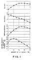
- Fig. 1 The magnetic properties of a bonded magnets prepared in this example are shown in Fig. 1.
- bonded magnets (resin content: 1.6 wt%) were prepared respectively from powder A1 alone and powder B1 alone. The bonded magnets thus molded were adhered to each other so that the amount of powder A1 was 25 wt% of total body.
- This composite bonded magnet will be hereinafter referred to as "Comparative Example 1-1.”
- Magnetization curves (demagnetization curves) for Example A and Comparative Example 1-1 are shown in Fig. 2. If an enhancement in magnetic properties is attributable only to an increase in packing density of magnetic powder alone, both the magnetization curves should be in agreement with each other. However, the magnetization of Example A shows higher value than that of Example B at any magnetic field. This demonstrates that Example A has an improved alignment over the magnet molded by employing a single powder. Further, the magnetization curve for Comparative Example 1-1 has a dent in a region of from 8 to 11 kOe (x80 kA/m) of magnetic field, whereas no dent is observed in the magnetization curve for Example A. This is because in Example A, the magnetic interaction occurred among different particles.
- the aged ingot was pulverized by means of a stamp mill and an attritor to prepare a powder having an average particle diameter of 21 ⁇ m.
- This powder had a coercive force of 7.9 kOe (x80 kA/m).
- This powder was mixed with 25 wt% powder A1, and the mixture was further mixed and milled together with 1.6 wt% an epoxy resin.
- the resultant mixture was subjected to compression molding at a pressure of 7 ton/cm 2 in a magnetic field of 15 kOe (x80 kA/m).
- the molded body was cured in a nitrogen gas atmosphere at 150°C for one hr to prepare a bonded magnet.
- This bonded magnet will be hereinafter referred to as "Comparative Example 1-2.”
- bonded magnets were prepared from the respective two powders used in Comparative Example 1-2 and adhered to each other.
- This composite magnet will be hereinafter referred to as "Comparative Example 1-3.” Magnetization curves for both magnets are shown in Fig. 3. As can be seen from Fig. 3, the magnetization curve for Comparative Example 1-2 is substantially in agreement with that for Comparative Example 1-3. From the above results, it can be understood that a high magnetic property by virtue of magnetic interaction cannot be obtained without mixing two magnetic powders different from each other in coercive force.
- Example B Powder A1 and powder B1 used in Example 1 were mixed together in a weight ratio of 1 : 3 using a twin-cylinder mixer. The mixture was further mixed and kneaded together with 1.6 wt% of an epoxy resin. The resultant compound was subjected to compression molding at a molding pressure of 7 ton/cm 2 in a magnetic field of 15 kOe (x80 kA/m). The molded body was cured in a nitrogen atmosphere at 150°C for one hr to prepare a bonded magnet. This bonded magnet will be hereinafter referred to as "Example B.”
- Example B powder A1 and powder B1 were separately mixed and kneaded together with 1.6 wt% of an epoxy resin.
- the resultant compounds were again mixed and kneaded together so that the ratio of A1 to B1 was 1 : 3.
- the resultant compound was then subjected to compression molding at a pressure of 7 ton/cm 2 in a magnetic field of 15 kOe (x80 kA/m), and the molded body was cured in a nitrogen atmosphere at 150°C for one hr to prepare a bonded magnet.
- This bonded magnet will be hereinafter referred to as "Comparative Example 2.”
- the magnetic properties of Example B and Comparative Example 2 are tabulated below.
- Example B had high magnetic property, whereas the properties of Comparative Example 2 were low due to a deterioration in squareness. Therefore, it can be understood that sufficient mixing of powders followed by molding of a bonded magnet enables strong magnetic interaction to work among different particles, so that a high-performance bonded magnet can be obtained.
- Cylindrical bonded magnets having a diameter of 10 mm and a height of 7 mm were prepared from Example B, Comparative Example 1-2 and a bonded magnet (Comparative Example 3) comprising powder A1 and, 4 wt% of an epoxy resin. They were subjected to an exposing test at 150°C for 1000 hrs. The magnetization loss of the cylindrical bonded magnets are tabulated below.
- Ex. B Comp.Ex. 1-2
- Comp.Ex. 2 Comp.Ex. 3
- Demagnetization (%) 4.8 10.2 7.3 46.3
- Example B is superior in temperature characteristics to the other bonded magnets.
- An ingot was prepared by melting and casting using an induction furnace in an argon gas atmosphere, resulting in the ingot's composition comprised 24.2 wt% of Sm, 45.7 wt% of Co. 22.9 wt% of Fe, 5.3 wt% of Cu and 1.9 wt% of Zr.
- This ingot was subjected to a solution heat treatment in an argon atmosphere at 1150°C for 24 hrs. Thereafter, the treated ingot was then aged at 800°C for 12 hrs and continuously cooled to 400°C at a rate of 0.5°C/min. Thereafter, the aged ingot was coarsely crushed by means of a stamp mill to an average particle diameter of 200 ⁇ m. This powder was designated as "B2.”
- Example C The magnetic properties of Example C are shown below.
- Br 10.9 kG (x10 -1 T)
- iHc 12.3 kOe (x80 kA/m)
- Example C has higher magnetic properties than Example A.
- Fig. 4(A) Demagnetization curves for Example C and Example A are shown in Fig. 4(A). Both the demagnetization curves are substantially in agreement with each other. However, when the magnetization difference between both samples curves are strictly observed, Fig. 4(B) is provided, suggesting that an improvement in squareness can be obtained by simultaneous pulverization and mixing. From the above results, it can be understood that simultaneous pulverization and mixing contribute to an improvement in magnetic interaction among particles because fresh surfaces come into contact with one another, so that high magnetic properties can be obtained.
- Example C and Example A were kept in air at 150°C for 100 hrs. Demagnetization curves for Example C and Example A after the above treatment are shown in Fig. 4(C). From Fig. 4(C), it can be clearly understood that Example C is superior to Example A in temperature characteristics.
- An ingot was prepared by melting and casting using an induction furnace in an argon gas atmosphere, resulting in the ingot's composition comprised 24.5 wt% of Sm and 75.5 wt% of Fe.
- the ingot was subjected to a homogenization heat treatment at 1100°C for 24 hrs and coarsely crushed to an average particle diameter of 100 ⁇ m by means of a stamp mill.
- the powder was nitrided at 450°C for one hr in a mixed gas of hydrogen and ammonia. It was then pulverized by means of a jet mill. At that time, the coercive force was varied by varying the pulverization time.
- the resultant powders are collectively referred to as "X.”
- an ingot was prepared by melting and casting using an induction furnace in an argon gas atmosphere resulting in the composition comprised 24.2 wt% of Sm, 45.7 wt% of Co, 22.9 wt% of Fe, 5.3 wt% Cu and 1.9 wt% of Zr.
- This ingot was subjected to a solution heat treatment in an argon atmosphere at 1150°C for 24 hrs. Thereafter, the treated ingot was aged at 800°C for 1 to 24 hrs and continuously cooled to 400°C at a rate of 0.5°C/min. In this case, the coercive force was varied by varying the aging treatment time. Thereafter, pulverization was carried out by means of stamp mill and attritor.
- the resultant powders are collectively referred to as "Y.”
- Powder X and powder Y were mixed together so that the X content was 25 wt%.
- the mixed powder was mixed and kneaded together with 1.6 wt% of an epoxy resin, and the resultant compound was subjected to compression molding in a magnetic field of 15 kOe (x80 kA/m) at a molding pressure of 7 ton/cm 2 and cured in a nitrogen atmosphere at 150°C for one hr to prepare bonded magnets.
- the magnetic properties of the bonded magnets were measured, and the results are shown in Fig. 5.
- An ingot was prepared by melting and casting using an induction furnace in an argon gas atmosphere, resulting in the composition comprised 24.5 wt% of Sm and 75.5 wt% of Fe.
- the ingot was subjected to a homogenization heat treatment at 1100°C for 24 hrs and coarsely crushed to an average particle diameter of 100 ⁇ m by means of a stamp mill.
- the powder was nitrided at 450°C for one hr in a mixed gas of hydrogen and ammonia. It was then pulverized by means of jet mill. At that time, the average powder particle diameter was varied by varying the pulverization time.
- the resultant powders are collectively referred to as "X2.”
- the average particle diameters were shown in Table 1.
- an ingot was prepared by melting and casting using an induction furnace in an argon gas atmosphere, resulting in the composition comprised 24.2 wt% of Sm, 45.7 wt% of Co, 22.9 wt% of Fe, 5.3 wt% of Cu and 1.9 wt% of Zr.
- This ingot was subjected to a solution heat treatment in an argon atmosphere at 1150°C for 24 hrs. Thereafter, the treated ingot was then aged at 800°C for 12 hrs and continuously cooled to 400°C at a rate of 0.5°C/min. Thereafter, pulverization was carried out by means of stamp mill and attritor.
- Powder X2 and powder Y2 were mixed together so that the X2 content was 25 wt%.
- the mixed powder was mixed and kneaded together with 1.6 wt% of an epoxy resin, and the resultant compound was subjected to compression molding in a magnetic field of 15 kOe (x80 kA/m) at a pressure of 7 ton/cm 2 and cured in a nitrogen atmosphere at 150°C for one hr to prepare bonded magnets.
- the magnetic properties of the bonded magnets were measured, and the results are shown in Table 1.
- Particle diameter of X2 ( ⁇ m) Particle Diameter of Y2 ( ⁇ m) (BH) max (MGOe (x8 kJ/m 3 )) Comp.Ex.
- Magnetic powder A1 obtained and magnetic powder B1 were mixed so that powder A1 content was 25 wt%. At that time, the mixing time was varied to vary the degree of dispersion between different powders. The degree of dispersion was roughly estimated in terms of the value a defined in claim 3 of the prevent application. Since the total amount of the mixed powder was 100 g, 1 g of the mixed powder was randomly sampled therefrom. The mixing ratio of A1 to B1 was measured from the 1g sample to determine the value a. The results are shown in Fig. 6.
- the magnetic properties of Example D were as follows.
- the properties of a bonded magnet as Comparative Example 4 prepared by using powder B3 alone are also given below.
- BH) max MGOe (x8 kJ/m 3 )
- Example D had very high magnetic properties by virtue of magnetic interaction.
- An ingot was prepared by melting and casting using an induction furnace in an argon gas atmosphere, resulting in the composition comprised 6.7 wt% of Sm, 2.3 wt% of Ce, 6.8 wt% of Pr, 6.9 wt% of Nd, 51.2 wt% of Co, 15.39 wt% of Fe, 6.8 wt% of Cu and 3.4 wt% of Zr.
- This ingot was subjected to a solution heat treatment in an argon atmosphere at 1145°C for 24 hrs. Thereafter, the treated ingot was then aged at 780°C for 12 hrs and continuously cooled to 400°C at a rate of 0.5°C/min.
- the aged ingot was pulverized by means of stamp mill and attritor to prepare a powder having an average particle diameter of 20 ⁇ m.
- This powder was designated as "B4.”
- the powder had a coercive force of 10.5 kOe (x80 kA/m).
- an ingot was prepared by melting and casting using an induction furnace in an argon gas atmosphere, resulting in the composition comprised 22.5 wt% of Sm, 2.3 wt% of Pr, 70.1 wt% of Fe and 5.1 wt% of Co.
- the ingot was subjected to a homogenization heat treatment at 1100°C for 24 hrs and coarsely crushed to an average particle diameter of 100 ⁇ m by means of stamp mill.
- the powder was nitrided at 450°C for 2 hrs in a mixed gas of hydrogen and ammonia. It was then pulverized by means of jet mill to prepare a fine powder having an average particle diameter of 2.2 ⁇ m.
- the fine powder was designated as "A2.”
- the coercive force of this powder was measured to be 6.5 kOe (x80 kA/m).
- Example E Powder A2 and powder B4 were mixed and kneaded together in a weight ratio of A2 to B4 of 1 : 3.
- the resultant compound was subjected to compression molding in a magnetic field of 15 kOe (x80 kA/m) at a pressure of 7 ton/cm 2 and cured in a nitrogen atmosphere at 150°C for one hr to prepare a bonded magnet.
- This bonded magnet will be hereinafter referred to as "Example E.”
- the magnetic properties of Example E are shown below.
- Br 10.2 kG (x10 -1 T)
- iHc 9.1 kOe (x80 kA/m)
- BH) max 23.5 MGOe (x8 kJ/m 3 )
- Example E Despite the fact that the Sm content of Example E was lower than that of Example A, Example E exhibited sufficiently high magnetic properties.
- Example F magnetizing in a powder (compound) form has enabled Example F to have an enhanced Br value over Example A.
- An alloy comprising. 10.5 wt% Sm and 89.5 wt% Fe, which had been prepared by using Sm having a purity of 99.9% and Fe having a purity of 99.9%, was prepared using an induction furnace in an Ar atmosphere.
- the resultant ingot was then subjected to a homogenization heat treatment in an Ar atmosphere at 1100°C for 24 hrs. Thereafter, the ingot was coarsely crushed to a powder particle diameter of about 100 ⁇ m and then carbonized in an acetylene gas at 450% for one hr.
- the resultant powder was pulverized to an average particle diameter of 5 ⁇ m. This powder was designated as "A3.”
- An ingot was prepared by melting and casting using an induction furnace in an argon gas atmosphere, resulting in the composition comprised 24.2 wt% of Sm, 45.7 wt% of Co, 22.9 wt% of Fe, 5.3 wt% of Cu and 1.9 wt% of Zr.
- This ingot was subjected to a solution heat treatment in an argon atmosphere at 1150°C for 24 hrs. Thereafter, the treated ingot was then aged at 800°C for 12 hrs and continuously cooled to 400°C at a rate of 0.5°C/min. Thereafter, the aged ingot was pulverized by means of stamp mill and attritor to prepare a powder having an average particle diameter of 21 ⁇ m.
- Powder A2 was mixed and milled together with 1.6 wt% of an epoxy resin, subjected to compression molding in a magnetic field of 15 kOe (x80 kA/m) at a pressure of 7 ton/cm 2 and cured at 150°C for one hr to prepare a bonded magnet.
- This bonded magnet was designated as "Comparative Example 5.”
- an ingot was prepared by melting and casting, resulting in the composition comprised 25.8 wt% of Sm, 44.9 wt% of Co, 24.8 wt% of Fe, 3.2 wt% of Cu and 1.3 wt% of Zr.
- the ingot was then subjected to a solution heat treatment in an argon atmosphere at 1120°C for 48 hrs. Thereafter, the treated ingot was then aged at 800°C for 15 hrs and continuously cooled to 400°C at a rate of 0.5°C/min. Thereafter, the aged ingot was pulverized by means of stamp mill and attritor to prepare a powder having an average particle diameter of 23 ⁇ m.
- Powder B4 was mixed and kneaded together with 1.6 wt% of an epoxy resin, subjected to compression molding in a magnetic field of 15 kOe (x80 kA/m) at a pressure of 7 ton/cm 2 and cured at 150°C for one hr to prepare a bonded magnet.
- This bonded magnet was designated as "Comparative Example 6.”
- the above two powders were mixed together so as to meet the relationship ⁇ (a)xA2 ⁇ + ⁇ (100- a)B4 ⁇ wherein a is, in wt%, 0 (Comparative Example 6), 20, 40, 60, 80 and 100 (Comparative Example 5).
- the mixed powder was mixed and kneaded together with 1.6 wt% of an epoxy resin, subjected to compression molding in a magnetic field of 15 kOe (x80 kA/m) at a pressure of 7 ton/cm 2 and cured at 150°C for one hr to prepare a bonded magnet.
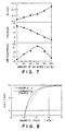
- the magnetic properties of the bonded magnet are shown in Fig. 7. As is apparent from Fig.
- Example G The magnetic properties of Example G, Comparative Example 5 and Comparative Example 6 were as follows. Br (kG (x10 -1 T)) iHc (kOe (x80 kA/m)) (BH) max (MGOe (x8 kJ/m 3 )) Ex. G 9.6 9.5 21.2 Comp.Ex. 5 9.2 12.5 18.5 Comp.Ex. 6 10.2 7.2 18.8
- bonded magnets were prepared respectively from powder A2 alone and powder B4 alone. The two bonded magnets thus formed were adhered to each other so that the amount of powder A2 was 40 wt%.
- This composite bonded magnet will be hereinafter referred to as "Comparative Example 7.”
- Magnetization curves (demagnetization curves) for Example G and Comparative Example 7 are shown in Fig. 8.
- the magnetization curve for Comparative Example 7 had a dent in a region of from 5 to 9 kOe (x80 kA/m), whereas no dent was observed in the magnetization curve for Example G. This is because, in Example G, magnetic interaction occurred among different particles.
- the term "dent" used herein is intended to mean that an inflection point is present in a magnetization curve of the second quadrant (the fourth quadrant).
- An ingot was prepared by melting and casting using an induction furnace in an argon gas atmosphere, resulting in the composition comprised 10.0 wt% of Sm, 14.0 wt% of Pr, 46.3 wt% of Co, 21.6 wt% of Fe, 6.2 wt% of Cu and 1.9 wt% of Zr.
- This ingot was subjected to a solution heat treatment in an argon atmosphere at 1130°C for 48 hrs. Thereafter, the treated ingot was then aged at 800°C for 12 hrs and continuously cooled to 400°C at a rate of 0.5°C/min. Thereafter, the aged ingot was pulverized by means of stamp mill and attritor to prepare a powder having an average particle diameter of 20 ⁇ m.
- Powder C1 was mixed and milled together with 1.6 wt% of an epoxy resin, subjected to compression molding in a magnetic field of 15 kOe (x80 kA/m) at a pressure of 7 ton/cm 2 and cured at 150°C for one hr to prepare a bonded magnet.
- This bonded magnet was designated as "Comparative Example 7.”
- Example H Powder C1 and Powder A2 were mixed together in a weight ratio of 13 : 7, and the mixed powder was further mixed and kneaded together with 1.6 wt% of an epoxy resin, subjected to compression molding in a magnetic field of 15 kOe (x80 kA/m) at a pressure of 7 ton/cm 2 and cured at 150°C for one hr to prepare a bonded magnet.
- This bonded magnet will be hereinafter referred to as "Example H.”
- the above procedure was repeated to prepare a bonded magnet, except that in the case of the magnets in which powder C1 alone was used.
- This bonded magnet will be hereinafter referred to as "Comparative Example 8.”
- the magnetic properties of Example H and Comparative Example 8 are tabulated below.
- Example H had high magnetic properties, whereas Comparative Example 8 had a deteriorated performance due to a low coercive force.
- An ingot was prepared by melting and casting using an induction furnace in an argon gas atmosphere, resulting in the composition comprised 12.4 wt% of Sm, 11.9 wt% of Nd, 46.2 wt% of Co, 21.5 wt% of Fe, 6.1 wt% of Cu and 1.9 wt% of Zr.
- This ingot was subjected to a solution heat treatment in an argon atmosphere at 1140°C for 48 hrs. Thereafter, the treated ingot was then aged at 800°C for 12 hrs and continuously cooled to 400°C at a rate of 0.5°C/min. Thereafter, the aged ingot was pulverized by means of stamp mill and attritor to prepare a powder having an average particle diameter of 22 ⁇ m.
- Powder D1 was mixed and kneaded together with 1.6 wt% of an epoxy resin, subjected to compression molding in a magnetic field of 15 kOe (x80 kA/m) at a pressure of 7 ton/cm 2 and cured at 150°C for one hr to prepare a bonded magnet.
- This bonded magnet was designated as "Comparative Example 9.”
- Example I Powder D1 and powder A2 were mixed together in a weight ratio of 60 : 40, and the mixture was further mixed and kneaded together with 1.6 wt% of an epoxy resin, subjected to compression molding in a magnetic field of 15 kOe (x80 kA/m) at a molding pressure of 7 ton/cm 2 and cured at 150°C for one hr to prepare a bonded magnet.
- This bonded magnet will be hereinafter referred to as "Example I.”
- the above procedure was repeated to prepare a bonded magnet, except that powder C1 alone was used.
- This bonded magnet will be hereinafter referred to as "Comparative Example 10.”
- the magnetic properties of Example I and Comparative Example 10 are tabulated below.
- Example I had high magnetic properties, whereas Comparative Example 10 had no satisfactory performance due to a low coercive force.
- An ingot was prepared by melting and casting using an induction furnace in an argon gas atmosphere in such a manner that the composition comprised 24.2 wt% of Sm, 44.9 wt% of Co, 26.5 wt% of Fe, 3.2 wt% of Cu and 1.2 wt% of Zr.
- the ingot was subjected to a solution heat treatment in an argon atmosphere at 1120°C for 48 hrs. Thereafter, the treated ingot was then aged at 800°C for a given period of time and then continuously cooled to 400°C at a rate of 0.5°C/min.
- the coercive force was varied by varying the aging time (1-24 hrs).
- Powders X2 and powders Y2 were mixed together in a mixing ratio of 3 : 2.
- 1.6 wt% of an epoxy resin was added to the mixed powders, and they were mixed and kneaded together.
- the resultant compounds were subjected to compression molding in a magnetic field of 15 kOe (x80 kA/m) at a pressure of 7 ton/cm 2 and cured at 150°C for one hr to prepare bonded magnets.
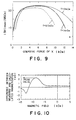
- the relationship between the coercive force and the obtained (BH) max is shown in Fig. 9.
- Ingots used for the preparation of powders A2, B4, C1 and D1 were designated respectively as A3, B5, C2 and D2. These ingots were coarsely crushed to an average particle diameter of about 200 ⁇ m.
- Examples J, K and L show higher magnetic properties than Examples G, H and I. This demonstrates that simultaneous pulverization and mixing of powders enhance magnetic interaction among particles (by virtue of contact of fresh surfaces) to provide high magnetic properties.
- Example 16 The compounds prepared in Example 16 were magnetized in a magnetic field of 40 kOe (x80 kA/m), subjected to compression molding in a magnetic field of 15 kOe (x80 kA/m) at a pressure of 7 ton/cm 2 and cured at 150°C for one hr to prepare bonded magnets. These bonded magnets were designated as "Example M,” “Example N,” and “Example O.” The magnetic properties thereof are tabulated below. Br (kG (x10 -1 T)) iHc (kOe (x80 kA/m)) (BH) max (MGOe (x8 kJ/m 3 )) Ex. M 10.6 10.2 23.4 Ex. N 11.2 11.5 24.1 Comp.Ex. 15 11.2 10.7 23.0
- Powder A1 and powder B1 were mixed together and pulverized in a weight ratio of 1 : 3.
- the mixed powder was mixed and kneaded together with 1.6 wt% of an epoxy resin.
- the resultant compound was molded in a magnetic field of 15 kOe (x80 kA/m).
- the density of magnetic powder was varied by varying the molding pressure.
- the magnitude of the magnetic interaction was evaluated in terms of the magnitude of a peak value of a magnetization difference between a demagnetization curve measured in reality magnetization and a demagnetization curve determined by calculation without the interaction. That the calculated magnetization curve is well in agreement with the curve measured in reality demagnetization curve without magnetic interaction has already been illustrated in Example 1.
- a typical variation in the differences between the measured values and the calculated values is shown in Fig. 10.
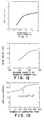
- Fig. 11 The relationship between the packing density of magnetic powder and the peak value is shown in Fig. 11. As is apparent from the drawing, it can be understood that the peak value increases with increasing the packing density of magnetic powder, which contributes to an improvement in squareness. In particular, the peak value rapidly decreases when the packing density of magnetic powder is not more than 50%, suggesting that the packing density of magnetic powder is critical to effective magnetic interaction.
- Powder A1 and powder B1 were mixed together and pulverized together in a weight ratio of 1 : 3 to prepare a mixed powder.
- the mixed powder was pressed at a pressure of 5 ton/cm 2 , a pulse current of 2000 A was allowed to flow, and plasma sintering was carried out at a sintering temperature of 400°C for 5 min.
- the resultant sintered magnet was designated as "Example P.”
- powder A1 and powder B1 were subjected to plasma sintering in such a manner that two layers were formed in the same composition as in Example P (i.e., so as to prepare a kind of a gradient material).
- the resultant magnet was designated as "Comparative Example 11.”
- Comparative Example 11 exhibited lowered magnetic properties due to occurrence of a dent, whereas Example P showed a very good squareness, which contributed to an enhancement in magnetic properties.
- An ingot was prepared by melting and casting using an induction furnace in an argon gas atmosphere, resulting in the composition comprised 24.2 wt% of Sm, 45.7 wt% of Co, 22.9 wt% of Fe, 5.3 wt% of Cu and 1.9 wt% of Zr. This ingot was subjected to a solution heat treatment in an argon atmosphere at 1150°C for 12 hrs. This treated ingot was designated as "K1.”
- an ingot was prepared by melting and casting, resulting in the composition comprised 10.0 wt% of Sm, 14.0 wt% of Pr, 46.3 wt% of Co, 21.6 wt% of Fe, 6.2 wt% of Cu and 1.9 wt% of Zr.
- This ingot was subjected to a solution heat treatment in an argon atmosphere at 1130°C for 24 hrs. This treated ingot was designated as "K2.”
- Ingots K1 and K2 were milled together in a weight ratio of 13 : 7, by means of jet mill (so that pulverization and mixing were simultaneously carried out).
- the mixed powder was molded in a magnetic field of 15 kOe (x80 kA/m), and the resultant molded body was sintered at 1200°C. Thereafter, the sinter body was subjected to a solution heat treatment at 1130°C for 24 hrs and aged at 800°C for 12 hrs and then continuously cooled to 400°C at a rate of 0.5°C/min.
- the sintered magnet thus prepared had the following performance.
- Br 13.1 kG (x10 -1 T)
- iHc 11.5 kOe (x80 kA/m)
- (BH) max 38.1 MGOe (x8 kJ/m 3 )
- Example 20 The mixed powder prepared in Example 20 was molded in a magnetic field of 15 kOe (x80 kA/m) at varied molding pressures. Sintered magnets were prepared from the molded body in the same manner as in Example 20. The packing density of magnetic powder was varied by varying the molding pressure as described above. The relationship between the packing density of magnetic powder and the peak value of the difference as an index of the magnetic interaction determined in Example 18 is shown in Fig. 12. As is apparent from the drawing, the peak value increased, that is, the squareness improved, with increasing the packing fraction. In particular, a rapid increase in the peak was observed when the packing density of magnetic powder was not less than 95%, illustrating that the packing fraction is critical to effective magnetic interaction.
- Powder L1 and Powder B1 were mixed together in a ratio of 3 : 2, and the mixture was further mixed and milled together with 1.6 wt% of an epoxy resin and molded in a magnetic field of 15 kOe (x80 kA/m). Thereafter, the molded body was cured at 150°C for one hr to prepare a bonded magnet.
- the magnetic properties of the bonded magnet are shown below.
- the composition was Fe 65 Co 35 .
- the resultant ingot was pulverized.
- This powder was designated as "M1.”
- Powder M1 and powder K1 were mixed together in a weight ratio of 1 : 9.
- the mixed powder was pulverized by means of a jet mill and molded in a magnetic field of 15 kOe (x80 kA/m).
- the molding was sintered at 1200°C.
- the sintered body was subjected to a solution heat treatment at 1130°C for 24 hrs and aged at 800°C for 12 hrs and continuously cooled to 400°C at a rate of 0.5°C/min.
- the sintered magnet had the following magnetic properties.
- Br 15.4 kG (x10 -1 T)
- iHc 8.1 kOe (x80 kA/m)
- (BH) max 50.1 MGOe (x8 kJ/m 3 )
- Powder M1 and powder A1 were mixed together in the weight ratio of 2 : 8.
- the mixed powder was pulverized by means of a jet mill, mixed and milled together with 1.6 wt% of an epoxy resin and molded in a magnetic field of 15 kOe (x80 kA/m). Thereafter, the molding was cured at 150°C for one hr to prepare a bonded magnet.
- iHc 6.2 kOe (x80 kA/m)
- (BH) max 25.4 MGOe (x8 kJ/m 3 )
- Atomized Fe powder (average particle diameter is 2 ⁇ m) P1 and powder L1 were mixed together in a ratio of 1 : 9, and the mixed powder was mixed and kneaded together with 1.6 wt% of an epoxy resin and molded in a magnetic field of 15 kOe (x80 kA/m). Thereafter, the molded body was cured at 150°C for one hr to prepare a bonded magnet.
- iHc 10.2 kOe (x80 kA/m)
- (BH) max 26.2 MGOe (x8 kJ/m 3 )
- the sintered body was heat-treated at 1130°C for 24 hrs and aged at 800°C for 12 hrs and then continuously cooled to 400°C at a rate of 0.5°C/min.
- Powder R1 and powder A1 were mixed together in a weight ratio of 3 : 7, and the mixture was pulverized by means of a jet mill.
- the mixed powder was mixed and kneaded together with 4 wt% of an epoxy resin and molded in a magnetic field of 15 kOe (x80 kA/m). Thereafter, the molded body was cured at 150°C for one hr to prepare a bonded magnet.
- iHc 5.3 kOe (x80 kA/m)
- (BH) max 22.3 MGOe (x8 kJ/m 3 )
- Powder R1 and powder L1 were mixed together in a ratio of 1 : 9, and the mixed powder was mixed and kneaded together with 1.6 wt% of an epoxy resin and molded in a magnetic field of 15 kOe (x80 kA/m). The molding was cured at 150°C for one hr to prepare a bonded magnet.
- the magnetic properties of the bonded magnet are shown below.
- Br 10.6 kG (x10 -1 T)
- iHc 12.1 kOe (x80 kA/m)
- BH) max 21.5 MGOe (x8 kJ/m 3 )
- Powder R1 and powder M1 were mixed together in a weight ratio of 7 : 3.
- the mixed powder was pulverized by means of a jet mill and molded in a magnetic field of 15 kOe (x80 kA/m).
- the molded body was sintered at 1250°C and heat-treated at 850°C for 5 hrs.
- iHc 3.2 kOe (x80 kA/m)
- (BH) max 19.6 MGOe (x8 kJ/m 3 )
- Powder S1 and powder A1 were mixed together in a ratio of 2 : 8, and the mixed powder was mixed and kneaded together with 1.6 wt% of an epoxy resin and molded in a magnetic field of 15 kOe (x80 kA/m).
- the molded body was cured at 150°C for one hr to prepare a bonded magnet.
- the magnetic properties of the bonded magnet are shown below.
- Br 10.7 kG (x10 -1 T)
- iHc 10.6 kOe (x80 kA/m)
- Powder S1 and powder L1 were mixed together in a weight ratio of 3 : 17, and the mixed powder was mixed and kneaded together with 1.6 wt% of an epoxy resin and molded in a magnetic field of 15 kOe (x80 kA/m). The molding was cured at 150°C for one hr to prepare a bonded magnet.
- the magnetic properties of the bonded magnet are shown below.
- Br 10.7 kG (x10 -1 T)
- iHc 10.6 kOe (x80 kA/m)
- Powder S1 and powder Q1 were mixed together in a ratio of 3 : 7, and the mixed powder was mixed and kneaded together with 1.6 wt% of an epoxy resin and molded in a magnetic field of 15 kOe (x80 kA/m).
- the molded body was cured at 150°C for one hr to prepare a bonded magnet.
- the magnetic properties of the bonded magnet are shown below.
- Br 11.1 kG (x10 -1 T)
- iHc 4.7 kOe (x80 kA/m)
- Powder A1 and powder B1 were mixed together in a weight ratio of 1 : 3, 2.5 wt% of nylon 12 was added to the mixed powder, and they were kneaded together at 250°C.
- the mixture was pelletized by means of a pulverizer and molded in a magnetic field of 10 kOe (x80 kA/m) at 250°C to prepare a bonded magnet. In this case, the pressure was 1 ton/cm 2 .
- iHc 10.3 kOe (x80 kA/m)
- (BH) max 22.4 MGOe (x8 kJ/m 3 )
- the molding at a relatively high temperature lead a bonded magnet having a sufficiently high alignment and a high packing density of magnetic powder even in a low magnetic field far alignment and at a low molding pressure.
- Powder A1 and powder B1 were mixed together in a ratio of 1 : 3, 10 wt% of nylon 12 was added to the mixed powder, and they were kneaded together at 280°C.
- the compound was injection-molded at 280°C and an injection pressure of 1 ton/cm 2 in a magnetic field of 15 kOe (x80 kA/m).
- the magnetic properties of the bonded magnet thus prepared are shown below.
- Br 8.5 kG (x10 -1 T)
- iHc 9.8 kOe (x80 kA/m)
- iHc 10.0 kOe (x80 kA/m)
- BH) max 21.0 MGOe (x8 kJ/m 3 )
- Powder A1 and powder B1 were mixed together in a weight ratio of 1 : 3.
- the average particle diameters of powder A1 and powder B1 were respectively 2.0 ⁇ m (rA) and 21.0 ⁇ m (rB).
- the mixing was carried out by means of a twin-cylinder mixer with varied mixing times.
- the mixed powders were mixed and milled together with 1.6 wt% of an epoxy resin, and the resultant compound was molded in a magnetic filed of 15 kOe (x80 kA/m).
- the moldings were cured at 150°C for one to prepare a bonded magnet.
- the sections of the bonded magnets were observed under a scanning electron microscope (SEM) to measure the number of contacting points of A1 with B1 (average for 10 points).
- SEM scanning electron microscope
Landscapes
- Engineering & Computer Science (AREA)
- Power Engineering (AREA)
- Chemical & Material Sciences (AREA)
- Crystallography & Structural Chemistry (AREA)
- Inorganic Chemistry (AREA)
- Physics & Mathematics (AREA)
- Spectroscopy & Molecular Physics (AREA)
- Dispersion Chemistry (AREA)
- Hard Magnetic Materials (AREA)
Claims (34)
- Magnetisches Pulver, umfassend eine Mischung aus zwei oder mehr Pulvern, enthaltend ein magnetisches Pulver A mit einer Restmagnetflußdichte BrA und einer Koerzitivkraft HcA sowie ein magnetisches Pulver B mit einer Restmagnetflußdichte BrB und einer Koerzitivkraft HcB, wobei die Restmagnetflußdichten und die Koerzitivkräfte die folgenden Beziehungen aufweisen:BrA > BrB und
- Magnetisches Pulver nach Anspruch 1, bei dem die Restmagnetflußdichten die folgende Beziehung aufweisen:
- Magnetisches Pulver nach Anspruch 1, bei dem in dem Mischpulver mit dem Gesamtgewichtsverhältnis von Pulver A zu Pulver B von i : j, wenn das lokale Gewichtsverhältnis des Pulvers A zum Pulver B in willkürlich als Probe entnommenen 1 % der Gesamtmenge des Mischpulvers i' : j' ist, das Mischpulver ein Erfordernis erfüllt, das durch die Formel
- Magnetisches Pulver nach Anspruch 3, wobei a = 0,9≤a≤1,1.
- Magnetisches Pulver nach Anspruch 1, bei dem die Anzahl n an Kontaktpunkten des magnetischen Pulvers A mit einem mittleren Pulverteilchendurchmesser rA zu dem magnetischen Pulver B mit einem mittleren Pulverteilchendurchmesser rB in dem Mischpulver
- Bondmagnet, der aus einem magnetischen Pulver nach einem der Ansprüche 1 bis 5 hergestellt ist.
- Bondmagnet nach Anspruch 6, bei dem die Packungsdichte des magnetischen Pulvers nicht weniger als 50 % ist.
- Sintermagnet, der aus einem magnetischen Pulver nach einem der Ansprüche 1 bis 5 hergestellt ist.
- Sintermagnet nach Anspruch 8, bei dem die Packungsdichte des magnetischen Pulvers nicht weniger als 95 % ist.
- Magnetisches Pulver nach Anspruch 1, bei dem das magnetische Pulver A ein Seltenerdmetall (wobei das Seltenerdmetall zumindest ein Mitglied ist, das aus den Seltenerdelementen einschließlich Y ausgewählt ist; hier nachstehend mit "R" bezeichnet), ein Übergangsmetall (wobei sich das Übergangsmetall hauptsächlich aus Fe und/oder Co zusammensetzt; hier nachstehend mit "TM" bezeichnet) und Stickstoff, Kohlenstoff und/oder Wasserstoff: ein R2TM17(NCH)x-System umfaßt, und das magnetische Pulver B R und Co und optionale Bestandteile einschließlich Fe, Cu und Zr: ein R2TM17-System umfaßt.
- Bondmagnet, der aus einem magnetischen Pulver nach Anspruch 10 hergestellt ist.
- Bondmagnet nach Anspruch 11, bei dem der Wert der Differenz zwischen dem Gewichtsprozentwert irgendeines der ein Mischpulver bildenden Pulver, bei dem der Maximalwert der Packungsdichte des magnetischen Pulvers erzielt wird, und dem Gewichtsprozentwert von demjenigen der ein Mischpulver bildenden Pulver, bei dem der Maximalwert des maximalen Energieprodukts (BH)max erzielt wird, nicht weniger als 5 Gew.-% ist.
- Magnetisches Pulver nach Anspruch 10, bei dem die mittleren Pulverteilchendurchmesser der Pulver die Beziehung rA < rB erfüllen.
- Magnetisches Pulver nach Anspruch 10, bei dem die mittleren Pulverteilchendurchmesser der Pulver folgende Beziehung erfüllen: 0,1 µm≤rA≤10 µm, 10 µm≤rB≤100 µm und rA < rB.
- Magnetisches Pulver nach Anspruch 1, bei dem das magnetische Pulver A R2TM17(NCH)x umfaßt und das magnetische Pulver B R, TM und B: ein R2TM14B-System umfaßt.
- Magnetisches Pulver nach Anspruch 1, bei dem das magnetische Pulver A ein R2TM17-System umfaßt und das magnetische Pulver 6 ein R2TM14-System umfaßt.
- Magnetisches Pulver nach Anspruch 1, bei dem das magnetische Pulver A ein R2TM14B-System umfaßt und das magnetische Pulver B ein R2TM17-System umfaßt.
- Magnetisches Pulver nach Anspruch 1, bei dem das magnetische Pulver A TM (hauptsächlich Fe) umfaßt und das magnetische Pulver B ein R2TM17-System umfaßt.
- Magnetisches Pulver nach Anspruch 1, bei dem das magnetische Pulver A TM (hauptsächlich Fe) umfaßt und das magnetische Pulver B ein R2TM17Nx-System umfaßt.
- Magnetisches Pulver nach Anspruch 1, bei dem das magnetische Pulver A TM (hauptsächlich Fe) umfaßt und das magnetische Pulver B ein R2TM14B-System umfaßt.
- Magnetisches Pulver nach Anspruch 1, bei dem das magnetische Pulver A TM (hauptsächlich Fe) umfaßt und das magnetische Pulver B ein RTM5-System umfaßt.
- Magnetisches Pulver nach Anspruch 1, bei dem das magnetische Pulver A TM und Stickstoff umfaßt und das magnetische Pulver B ein R2TM17-System umfaßt.
- Magnetisches Pulver nach Anspruch 1, bei dem das magnetische Pulver A TM und Stickstoff umfaßt und das magnetische Pulver B ein R2TM17Nx-System umfaßt.
- Magnetisches Pulver nach Anspruch 1, bei dem das magnetische Pulver A TM und Stickstoff umfaßt und das magnetische Pulver B ein R2TM14B-System umfaßt.
- Magnetisches Pulver nach Anspruch 1, bei dem das magnetische Pulver A TM und Stickstoff umfaßt und das magnetische Pulver B ein RTM5-System umfaßt.
- Magnetisches Pulver nach Anspruch 1, bei dem das magnetische Pulver A Ferrit umfaßt und das magnetische Pulver B ein R2TM17-System umfaßt.
- Magnetisches Pulver nach Anspruch 1, bei dem das magnetische Pulver A Ferrit umfaßt und das magnetische Pulver B ein R2TM17Nx-System umfaßt.
- Magnetisches Pulver nach Anspruch 1, bei dem das magnetische Pulver A Ferrit umfaßt und das magnetische Pulver B ein R2TM14B-System umfaßt.
- Magnetisches Pulver nach Anspruch 1, bei dem das magnetische Pulver A Ferrit umfaßt und das magnetische Pulver B ein RTM5-System umfaßt.
- Magnetisches Pulver nach Anspruch 1, bei dem das magnetische Pulver A ein RTM5-System umfaßt und das magnetische Pulver B ein R2TM17-System umfaßt.
- Magnetisches Pulver nach Anspruch 1, bei dem das magnetische Pulver A ein RTM5-System umfaßt und das magnetische Pulver B ein R2Fe14B-System umfaßt.
- Magnetisches Pulver nach Anspruch 1, bei dem das magnetische Pulver A ein RTM5-System umfaßt und das magnetische Pulver B ein R2TM17Nx-System umfaßt.
- Rondmagnet, der aus einem magnetischen Pulver nach einem der Ansprüche 13 bis 32 hergestellt ist.
- Bondmagnet, der aus einem magnetischen Pulver nach einem der Ansprüche 10 und 13 bis 32 hergestellt ist.
Applications Claiming Priority (3)
| Application Number | Priority Date | Filing Date | Title |
|---|---|---|---|
| JP28271793 | 1993-11-11 | ||
| JP282717/93 | 1993-11-11 | ||
| JP28271793 | 1993-11-11 |
Publications (3)
| Publication Number | Publication Date |
|---|---|
| EP0654801A2 EP0654801A2 (de) | 1995-05-24 |
| EP0654801A3 EP0654801A3 (de) | 1995-07-05 |
| EP0654801B1 true EP0654801B1 (de) | 2000-06-07 |
Family
ID=17656128
Family Applications (1)
| Application Number | Title | Priority Date | Filing Date |
|---|---|---|---|
| EP19940114972 Expired - Lifetime EP0654801B1 (de) | 1993-11-11 | 1994-09-22 | Magnetisches Pulver, Dauermagnet und Herstellungsverfahren |
Country Status (3)
| Country | Link |
|---|---|
| EP (1) | EP0654801B1 (de) |
| DE (1) | DE69424845T2 (de) |
| TW (1) | TW294815B (de) |
Families Citing this family (4)
| Publication number | Priority date | Publication date | Assignee | Title |
|---|---|---|---|---|
| FR2752641B1 (fr) * | 1996-08-20 | 1998-12-04 | Rhone Poulenc Chimie | Produit a proprietes magnetiques, son procede de preparation et aimant obtenu a partir de ce produit |
| WO2003085683A1 (en) * | 2002-04-09 | 2003-10-16 | Aichi Steel Corporation | Composite rare earth anisotropic bonded magnet, compound for composite rare earth anisotropic bonded magnet and method for preparation thereof |
| US7357880B2 (en) * | 2003-10-10 | 2008-04-15 | Aichi Steel Corporation | Composite rare-earth anisotropic bonded magnet, composite rare-earth anisotropic bonded magnet compound, and methods for their production |
| CN120048608A (zh) * | 2025-04-27 | 2025-05-27 | 横店集团东磁股份有限公司 | 一种防盗标签用磁体及其制备方法 |
Family Cites Families (5)
| Publication number | Priority date | Publication date | Assignee | Title |
|---|---|---|---|---|
| JPS58108708A (ja) * | 1981-12-23 | 1983-06-28 | Tohoku Metal Ind Ltd | 希土類永久磁石材料 |
| JPS59106106A (ja) * | 1982-12-10 | 1984-06-19 | Toshiba Corp | 永久磁石の製造方法 |
| JPH01274401A (ja) * | 1988-04-26 | 1989-11-02 | Tdk Corp | 永久磁石 |
| GB2232165A (en) * | 1989-03-22 | 1990-12-05 | Cookson Group Plc | Magnetic compositions |
| DE59200858D1 (de) * | 1991-03-08 | 1995-01-12 | Basf Ag | Eine neue kategorie magnetischer materialien, deren herstellung und anwendung. |
-
1994
- 1994-09-22 EP EP19940114972 patent/EP0654801B1/de not_active Expired - Lifetime
- 1994-09-22 DE DE1994624845 patent/DE69424845T2/de not_active Expired - Lifetime
- 1994-11-04 TW TW83110196A patent/TW294815B/zh not_active IP Right Cessation
Also Published As
| Publication number | Publication date |
|---|---|
| DE69424845D1 (de) | 2000-07-13 |
| TW294815B (de) | 1997-01-01 |
| DE69424845T2 (de) | 2000-12-07 |
| EP0654801A2 (de) | 1995-05-24 |
| EP0654801A3 (de) | 1995-07-05 |
Similar Documents
| Publication | Publication Date | Title |
|---|---|---|
| US5647886A (en) | Magnetic powder, permanent magnet produced therefrom and process for producing them | |
| US4921553A (en) | Magnetically anisotropic bond magnet, magnetic powder for the magnet and manufacturing method of the powder | |
| US4859255A (en) | Permanent magnets | |
| JP2751109B2 (ja) | 熱安定性の良好な焼結型永久磁石 | |
| US6139765A (en) | Magnetic powder, permanent magnet produced therefrom and process for producing them | |
| JP3275882B2 (ja) | 磁石粉末および等方性ボンド磁石 | |
| KR100363372B1 (ko) | 자석 분말 및 등방성 결합 자석 | |
| US5230751A (en) | Permanent magnet with good thermal stability | |
| US5230749A (en) | Permanent magnets | |
| US4891078A (en) | Rare earth-containing magnets | |
| KR100414463B1 (ko) | 자석 분말, 자석 분말의 제조방법 및 결합 자석 | |
| KR100367437B1 (ko) | 자석 분말 및 등방성 결합된 자석 | |
| JP2001155911A (ja) | 薄帯状磁石材料、磁石粉末および希土類ボンド磁石 | |
| US4601754A (en) | Rare earth-containing magnets | |
| JPS63317643A (ja) | 希土類―鉄―ボロン系磁気異方性焼結永久磁石原料用合金薄板並びに磁気異方性焼結永久磁石原料用合金粉末,及び磁気異方性焼結永久磁石 | |
| JPH0831626A (ja) | 希土類磁性粉末、その永久磁石及びこれらの製造方法 | |
| KR100392806B1 (ko) | 자석 분말 및 결합 자석 | |
| KR100363370B1 (ko) | 자석 분말 및 등방성 결합된 자석 | |
| US4776902A (en) | Method for making rare earth-containing magnets | |
| JPH0551656B2 (de) | ||
| JP3296507B2 (ja) | 希土類永久磁石 | |
| JP2001217112A (ja) | R−t−b系焼結磁石 | |
| EP0654801A2 (de) | Magnetisches Pulver, Dauermagnet und Herstellungsverfahren | |
| JPH10177911A (ja) | 希土類ボンド磁石 | |
| JP2935376B2 (ja) | 永久磁石 |
Legal Events
| Date | Code | Title | Description |
|---|---|---|---|
| PUAI | Public reference made under article 153(3) epc to a published international application that has entered the european phase |
Free format text: ORIGINAL CODE: 0009012 |
|
| PUAL | Search report despatched |
Free format text: ORIGINAL CODE: 0009013 |
|
| AK | Designated contracting states |
Kind code of ref document: A2 Designated state(s): DE FR GB IT |
|
| AK | Designated contracting states |
Kind code of ref document: A3 Designated state(s): DE FR GB IT |
|
| 17P | Request for examination filed |
Effective date: 19950907 |
|
| 17Q | First examination report despatched |
Effective date: 19970506 |
|
| GRAG | Despatch of communication of intention to grant |
Free format text: ORIGINAL CODE: EPIDOS AGRA |
|
| GRAG | Despatch of communication of intention to grant |
Free format text: ORIGINAL CODE: EPIDOS AGRA |
|
| GRAH | Despatch of communication of intention to grant a patent |
Free format text: ORIGINAL CODE: EPIDOS IGRA |
|
| GRAH | Despatch of communication of intention to grant a patent |
Free format text: ORIGINAL CODE: EPIDOS IGRA |
|
| GRAA | (expected) grant |
Free format text: ORIGINAL CODE: 0009210 |
|
| ITF | It: translation for a ep patent filed | ||
| AK | Designated contracting states |
Kind code of ref document: B1 Designated state(s): DE FR GB IT |
|
| REF | Corresponds to: |
Ref document number: 69424845 Country of ref document: DE Date of ref document: 20000713 |
|
| ET | Fr: translation filed | ||
| PLBE | No opposition filed within time limit |
Free format text: ORIGINAL CODE: 0009261 |
|
| STAA | Information on the status of an ep patent application or granted ep patent |
Free format text: STATUS: NO OPPOSITION FILED WITHIN TIME LIMIT |
|
| 26N | No opposition filed | ||
| REG | Reference to a national code |
Ref country code: GB Ref legal event code: IF02 |
|
| PGFP | Annual fee paid to national office [announced via postgrant information from national office to epo] |
Ref country code: DE Payment date: 20130918 Year of fee payment: 20 |
|
| PGFP | Annual fee paid to national office [announced via postgrant information from national office to epo] |
Ref country code: GB Payment date: 20130918 Year of fee payment: 20 Ref country code: FR Payment date: 20130910 Year of fee payment: 20 |
|
| PGFP | Annual fee paid to national office [announced via postgrant information from national office to epo] |
Ref country code: IT Payment date: 20130917 Year of fee payment: 20 |
|
| REG | Reference to a national code |
Ref country code: DE Ref legal event code: R071 Ref document number: 69424845 Country of ref document: DE |
|
| REG | Reference to a national code |
Ref country code: GB Ref legal event code: PE20 Expiry date: 20140921 |
|
| PG25 | Lapsed in a contracting state [announced via postgrant information from national office to epo] |
Ref country code: DE Free format text: LAPSE BECAUSE OF EXPIRATION OF PROTECTION Effective date: 20140923 |
|
| PG25 | Lapsed in a contracting state [announced via postgrant information from national office to epo] |
Ref country code: GB Free format text: LAPSE BECAUSE OF EXPIRATION OF PROTECTION Effective date: 20140921 |