EP0654805A2 - Festelektrolytkondensator und Herstellungsverfahren - Google Patents
Festelektrolytkondensator und Herstellungsverfahren Download PDFInfo
- Publication number
- EP0654805A2 EP0654805A2 EP94118043A EP94118043A EP0654805A2 EP 0654805 A2 EP0654805 A2 EP 0654805A2 EP 94118043 A EP94118043 A EP 94118043A EP 94118043 A EP94118043 A EP 94118043A EP 0654805 A2 EP0654805 A2 EP 0654805A2
- Authority
- EP
- European Patent Office
- Prior art keywords
- solid electrolyte
- electrolytic capacitor
- anode lead
- lead terminal
- solid electrolytic
- Prior art date
- Legal status (The legal status is an assumption and is not a legal conclusion. Google has not performed a legal analysis and makes no representation as to the accuracy of the status listed.)
- Granted
Links
- 239000003990 capacitor Substances 0.000 title claims abstract description 69
- 239000007787 solid Substances 0.000 title claims abstract description 47
- 238000004519 manufacturing process Methods 0.000 title claims description 19
- 239000007784 solid electrolyte Substances 0.000 claims abstract description 70
- 239000002322 conducting polymer Substances 0.000 claims abstract description 29
- 229920001940 conductive polymer Polymers 0.000 claims abstract description 29
- 238000005979 thermal decomposition reaction Methods 0.000 claims abstract description 19
- QVGXLLKOCUKJST-UHFFFAOYSA-N atomic oxygen Chemical compound [O] QVGXLLKOCUKJST-UHFFFAOYSA-N 0.000 claims abstract description 17
- 239000001301 oxygen Substances 0.000 claims abstract description 17
- 229910052760 oxygen Inorganic materials 0.000 claims abstract description 17
- 239000011347 resin Substances 0.000 claims description 12
- 229920005989 resin Polymers 0.000 claims description 12
- 229920000128 polypyrrole Polymers 0.000 claims description 10
- 238000005304 joining Methods 0.000 claims description 5
- 238000003466 welding Methods 0.000 claims description 4
- 229920000767 polyaniline Polymers 0.000 claims description 3
- 229920000123 polythiophene Polymers 0.000 claims description 3
- 239000004020 conductor Substances 0.000 claims 2
- 238000010438 heat treatment Methods 0.000 abstract description 12
- 238000000034 method Methods 0.000 description 16
- WABPQHHGFIMREM-VENIDDJXSA-N lead-201 Chemical compound [201Pb] WABPQHHGFIMREM-VENIDDJXSA-N 0.000 description 7
- 238000006116 polymerization reaction Methods 0.000 description 7
- MYMOFIZGZYHOMD-UHFFFAOYSA-N Dioxygen Chemical compound O=O MYMOFIZGZYHOMD-UHFFFAOYSA-N 0.000 description 6
- 239000007789 gas Substances 0.000 description 6
- 229910001882 dioxygen Inorganic materials 0.000 description 5
- 238000009413 insulation Methods 0.000 description 5
- 239000000126 substance Substances 0.000 description 5
- KAESVJOAVNADME-UHFFFAOYSA-N Pyrrole Chemical compound C=1C=CNC=1 KAESVJOAVNADME-UHFFFAOYSA-N 0.000 description 4
- 239000000853 adhesive Substances 0.000 description 4
- 230000001070 adhesive effect Effects 0.000 description 4
- OKKJLVBELUTLKV-UHFFFAOYSA-N Methanol Chemical compound OC OKKJLVBELUTLKV-UHFFFAOYSA-N 0.000 description 3
- 239000003960 organic solvent Substances 0.000 description 3
- PAYRUJLWNCNPSJ-UHFFFAOYSA-N Aniline Chemical compound NC1=CC=CC=C1 PAYRUJLWNCNPSJ-UHFFFAOYSA-N 0.000 description 2
- YTPLMLYBLZKORZ-UHFFFAOYSA-N Thiophene Chemical compound C=1C=CSC=1 YTPLMLYBLZKORZ-UHFFFAOYSA-N 0.000 description 2
- 230000003247 decreasing effect Effects 0.000 description 2
- 230000000694 effects Effects 0.000 description 2
- 239000011148 porous material Substances 0.000 description 2
- 238000001721 transfer moulding Methods 0.000 description 2
- OKTJSMMVPCPJKN-UHFFFAOYSA-N Carbon Chemical compound [C] OKTJSMMVPCPJKN-UHFFFAOYSA-N 0.000 description 1
- BQCADISMDOOEFD-UHFFFAOYSA-N Silver Chemical compound [Ag] BQCADISMDOOEFD-UHFFFAOYSA-N 0.000 description 1
- 239000007864 aqueous solution Substances 0.000 description 1
- 238000006243 chemical reaction Methods 0.000 description 1
- 238000007796 conventional method Methods 0.000 description 1
- 238000002309 gasification Methods 0.000 description 1
- 229910002804 graphite Inorganic materials 0.000 description 1
- 239000010439 graphite Substances 0.000 description 1
- 239000007800 oxidant agent Substances 0.000 description 1
- 230000005855 radiation Effects 0.000 description 1
- 239000005871 repellent Substances 0.000 description 1
- 238000011160 research Methods 0.000 description 1
- 229910052709 silver Inorganic materials 0.000 description 1
- 239000004332 silver Substances 0.000 description 1
- 239000000243 solution Substances 0.000 description 1
- 239000002904 solvent Substances 0.000 description 1
- 229910052715 tantalum Inorganic materials 0.000 description 1
- GUVRBAGPIYLISA-UHFFFAOYSA-N tantalum atom Chemical compound [Ta] GUVRBAGPIYLISA-UHFFFAOYSA-N 0.000 description 1
- 229930192474 thiophene Natural products 0.000 description 1
Images


Classifications
-
- H—ELECTRICITY
- H01—ELECTRIC ELEMENTS
- H01G—CAPACITORS; CAPACITORS, RECTIFIERS, DETECTORS, SWITCHING DEVICES, LIGHT-SENSITIVE OR TEMPERATURE-SENSITIVE DEVICES OF THE ELECTROLYTIC TYPE
- H01G9/00—Electrolytic capacitors, rectifiers, detectors, switching devices, light-sensitive or temperature-sensitive devices; Processes of their manufacture
- H01G9/004—Details
- H01G9/008—Terminals
- H01G9/012—Terminals specially adapted for solid capacitors
-
- H—ELECTRICITY
- H01—ELECTRIC ELEMENTS
- H01G—CAPACITORS; CAPACITORS, RECTIFIERS, DETECTORS, SWITCHING DEVICES, LIGHT-SENSITIVE OR TEMPERATURE-SENSITIVE DEVICES OF THE ELECTROLYTIC TYPE
- H01G9/00—Electrolytic capacitors, rectifiers, detectors, switching devices, light-sensitive or temperature-sensitive devices; Processes of their manufacture
- H01G9/004—Details
- H01G9/04—Electrodes or formation of dielectric layers thereon
- H01G9/042—Electrodes or formation of dielectric layers thereon characterised by the material
-
- H—ELECTRICITY
- H01—ELECTRIC ELEMENTS
- H01G—CAPACITORS; CAPACITORS, RECTIFIERS, DETECTORS, SWITCHING DEVICES, LIGHT-SENSITIVE OR TEMPERATURE-SENSITIVE DEVICES OF THE ELECTROLYTIC TYPE
- H01G9/00—Electrolytic capacitors, rectifiers, detectors, switching devices, light-sensitive or temperature-sensitive devices; Processes of their manufacture
- H01G9/15—Solid electrolytic capacitors
Definitions
- the present invention relates to a solid electrolytic capacitor and a method of manufacturing the same, in particular to a solid electrolytic capacitor of which the structure of a joint for joining an anode lead and an anode lead terminal is improved when conducting polymers are used as a solid electrolyte, and a method of manufacturing the same for realizing the structure of the joint improved as above.
- water-repellent insulation 112 is first applied or set onto a head of an anode body 102 which has an anode lead 101 planted thereon. Then, an oxide film (not shown), the solid electrolyte 104 and a cathode layer 105 are formed successively on the anode body 102 to form a capacitor element 110.
- the anode lead 101 and the anode lead terminal 106 are joined by welding, and the cathode layer 105 and a cathode lead terminal 107 are joined by means of a conductive adhesive 108.
- the capacitor element 110 is armored with resin 109 by a transfer molding method, except for a part of the anode lead terminal 106 and the cathode lead terminal 107. Further, a portion of the anode lead terminal 106 and the cathode lead terminal 107 exposed out of the resin 109 are bent along the resin 109, respectively, to form a chip type solid electrolytic capacitor.
- An object of the present invention is to provide a solid electrolytic capacitor having a solid electrolyte consisting of a conducting polymer and manufactured such that a short circuit will hardly occur between the solid electrolyte and an anode lead terminal being caused by the conducting polymer crawled up on the anode lead.
- Another object of the present invention is to provide a structure of the joint of an anode lead and an anode lead terminal for realizing a capacitor with high joint reliability as above without sacrificing electric capacity per volume of the capacitor and a method of manufacturing the capacitor which allows the realization of the structure as above.
- a solid electrolytic capacitor of the present invention is characterized by that it comprises a capacitor element having an oxide film and a solid electrolyte and a cathode layer all formed on an anode body which has an anode lead planted thereon, an anode lead terminal joined to an anode lead and a cathode lead terminal joined to a cathode layer, and a resin layer covering those substances, wherein the solid electrolyte is composed of conducting polymers such as pyrrole, thiophene, or aniline and in addition the insulated solid electrolyte is formed in the proximate area of the joint of the anode lead and the anode lead terminal.
- the solid electrolytic capacitor is manufactured by a manufacturing method characterized by that the solid electrolyte crawled up and formed on the anode lead is insulated being heated to a temperature below the thermal decomposition temperature using a thermal means such as heating by a heater chip, light irradiation or a hot air blast in the presence of oxygen molecules.
- the solid electrolytic capacitor of the present invention is characterized in that the solid electrolyte in the proximate area of the joint of the anode lead and the anode lead terminal is removed.
- the solid electrolytic capacitor is manufactured by a manufacturing method characterized by that the method removes the solid electrolyte crawled up and formed on the anode lead by heating and thermally decomposing thereof by using thermal means such as heating by a heater chip, light irradiation or a hot air blast, where the solid electrolyte being heated to a temperature equal to or more than the thermal decomposition temperature which is due under the presence of oxygen molecules.
- FIG. 1 is a sectional view of a conventional chip type solid electrolytic capacitor.
- FIG. 2 is a sectional view of a chip type solid electrolytic capacitor according to a first embodiment of the present invention.
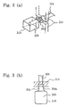
- FIG. 3(a) is a perspective view showing an insulating process of the first embodiment
- FIG. 3(b) is an external view of a capacitor element showing an insulated portion of the chip type solid electrolytic capacitor according to the first embodiment.
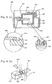
- FIG. 4(a) is a sectional view showing a chip type solid electrolytic capacitor according to a second embodiment of the present invention
- FIG. 4(b) is a perspective view showing a solid electrolyte removing process according to the second embodiment.
- FIG. 2 is a sectional view of a chip type solid electrolytic capacitor according to a first embodiment of the present invention.
- an oxide film 203 is first formed on an anode body 202 which has an anode lead 201 planted thereon by using a means well known to the public, then polypyrrole made of conducting polymers is formed as a solid electrolyte 204.
- polypyrrole is formed by chemical polymerization. More particularly, a pyrrole aqueous solution is first impregnated into pores of the anode body 202 to be dried, and then an organic solvent solution of an oxidizer is additionally impregnated to be processed by polymerization. In the present embodiment, methanol was used as an organic solvent. This chemical polymerization was implemented repeatedly 20 times, sufficiently forming polypyrrole in the pores. Thereafter, graphite and silver paste were impregnated and dried as a collector and an electrode, respectively, to form a cathode layer 205 thereby producing a capacitor element 210.
- anode lead terminal 206 and the cathode lead terminal 207 were armored, except a part thereof, with resin 209 by a transfer molding method, portions of the anode lead terminal 206 and the cathode lead terminal 207 exposed outside were bent along the armor resin 209, respectively, thereby producing a chip type solid electrolytic capacitor.
- FIG. 3(a) is a perspective view showing an insulating process
- FIG. 3(b) is an external view showing an insulated portion of a capacitor element 210.
- the solid electrolyte 204 crawled up and formed on the anode lead 201 of the capacitor element 210 with the cathode layer 205 which had already been formed thereon was placed between a heater chip 211 consisting of upper and lower pieces.
- a heater chip 211 consisting of upper and lower pieces.
- this heater chip 211 By heating this heater chip 211 at a temperature of about 270°C for 5 to 10 seconds, the insulated portion 204a of the solid electrolyte 204 was produced.
- the distance between the heater chip 211 and the anode body 202 was studied. Since the polypyrrole thermally decomposes at about 300°C in the presence of oxygen molecules, the temperature of the heater chip 211 was set to 270°C and the heating time to 5 seconds. In this case, the length of the solid electrolyte 204 crawled up on the anode lead 201 was 2 mm from the head of the anode body 202.
- the solid electrolyte 204 formed even on the anode body 202 is insulated by the radiation heat of the heater chip 211, and hence the control conditions (temperature, time) of the heater chip 211 is an important factor. With the conditions of the present embodiment, it was found that there was no problem even when the distance between the heater chip 211 and the anode body 202 was lessened to about 0.5 mm.
- the bias current error of the solid electrolytic capacitor of the present invention was decreased to 1/5 or less. Consequently, it became possible to elongate the anode body 202 in the direction of the anode lead 201, thereby improving the volume efficiency of the electric capacity.
- the length of the anode body 2 was elongated from 0.8 mm to 1.2 mm, thereby improving its efficiency by more than 50 %.
- the present embodiment has been described with reference to the process for insulating the solid electrolyte by using a heater chip as a heating means, however, the same insulating effect was obtained by heating through laser irradiation or a hot air blast.
- FIG. 4(a) is a sectional view showing a structure of the second embodiment of the present invention. Now, the second embodiment of the present invention will be described with reference to FIG. 4(a).
- partial heating was applied to a solid electrolyte 404 to thermally decompose and remove the solid electrolyte which had crawled up and formed on an anode lead 401 in a polypyrrole polymerization process (removed part is shown by solid electrolyte removed portion 404b in FIG. 4(a)). Thereafter, a chip type tantalum solid electrolytic capacitor was obtained through the same process as the first embodiment.
- an anode body 402 an oxide film 403, a cathode layer 405, an anode lead 406, a cathode lead terminal 407, a conductive adhesive 408 and resin 409 are similar to the anode body 102, oxide film 103, cathode layer 105, anode lead 106, cathode lead terminal 107, conductive adhesive 108 and resin 109 shown in FIG. 1, respectively.
- FIG. 4(b) is a perspective view showing a solid electrolyte removing process. An insulating process of the present embodiment will be described with reference to FIG. 4(b).
- the solid electrolyte 404 crawled up on the anode lead 401 of a capacitor element 410 on which the cathode layer 405 had already been formed was placed between a heater chip 411 composed of two pieces, an upper and a lower, and then the heater chip 411 was heated while being subjected to an oxygen gas stream blown from a side nozzle 413.
- the form of the heater chip 411 was the same as that of the first embodiment.
- the heating temperature of the chip 411 was set to 320°C.
- the heating time was 2 to 5 seconds.
- the thermal decompositions reaction from the heat of the chip in the oxygen gas streams caused the gasification of the solid electrolyte and it was substituted by a product gas produced by the thermal decomposition reaction with oxygen molecules, and the movement of the product gas which took place, removed the port of the solid electrolyte crawled up on the anode lead 1.
- the removed portion of the solid electrolyte is shown by a solid electrolyte removed portion 404b in FIG. 4(a).
- the heater chip in the same way as the first embodiment by using laser irradiation or a hot air blast.
- the oxygen gas stream supplied from a nozzle was applied from the viewpoint of high supply efficiency of oxygen molecules, which are required for thermal decomposition, that is, from the viewpoint that the oxygen gas stream had to be able to move the thermal decomposition product gas rapidly and at the same time the oxygen density in the supply gas had to be high, it was also possible to gain the same effect as the present embodiment by using an air stream when the conditions of the air were appropriately selected.
- the gas might be blown not only from the side direction of the heater chip but also from the upper and lower directions of the chip or from the direction along the anode lead, i.e., the direction parallel to the anode lead.
- the present invention is effective as follows.
Landscapes
- Engineering & Computer Science (AREA)
- Power Engineering (AREA)
- Microelectronics & Electronic Packaging (AREA)
- Chemical & Material Sciences (AREA)
- Materials Engineering (AREA)
- Fixed Capacitors And Capacitor Manufacturing Machines (AREA)
- Polyoxymethylene Polymers And Polymers With Carbon-To-Carbon Bonds (AREA)
Applications Claiming Priority (2)
| Application Number | Priority Date | Filing Date | Title |
|---|---|---|---|
| JP5288932A JP2718353B2 (ja) | 1993-07-29 | 1993-11-18 | 固体電解コンデンサおよびその製造方法 |
| JP288932/93 | 1993-11-18 |
Publications (3)
| Publication Number | Publication Date |
|---|---|
| EP0654805A2 true EP0654805A2 (de) | 1995-05-24 |
| EP0654805A3 EP0654805A3 (de) | 1995-07-19 |
| EP0654805B1 EP0654805B1 (de) | 1998-05-13 |
Family
ID=17736682
Family Applications (1)
| Application Number | Title | Priority Date | Filing Date |
|---|---|---|---|
| EP94118043A Expired - Lifetime EP0654805B1 (de) | 1993-11-18 | 1994-11-15 | Festelektrolytkondensator und Herstellungsverfahren |
Country Status (4)
| Country | Link |
|---|---|
| US (1) | US5752986A (de) |
| EP (1) | EP0654805B1 (de) |
| KR (1) | KR0158732B1 (de) |
| DE (1) | DE69410216T2 (de) |
Cited By (2)
| Publication number | Priority date | Publication date | Assignee | Title |
|---|---|---|---|---|
| US5699597A (en) * | 1994-05-30 | 1997-12-23 | Rohm Co., Ltd. | Method of manufacturing a tantalum solid state electrolytic capacitor |
| EP1022752A3 (de) * | 1999-01-25 | 2004-02-18 | NEC TOKIN Toyama, Ltd. | Verfahren zum Herstellen eines Festelektrolytkondensator |
Families Citing this family (4)
| Publication number | Priority date | Publication date | Assignee | Title |
|---|---|---|---|---|
| DE69833149T2 (de) * | 1997-06-20 | 2006-09-07 | Matsushita Electric Industrial Co., Ltd., Kadoma | Elektrolytkondensator und dessen Herstellungsverfahren |
| JP3228323B2 (ja) * | 1997-09-10 | 2001-11-12 | 日本電気株式会社 | 固体電解コンデンサおよびその製造方法 |
| US6079744A (en) * | 1998-04-24 | 2000-06-27 | Breed Automotive Technology, Inc. | Device to detect seat belt buckle status |
| JP2007134629A (ja) * | 2005-11-14 | 2007-05-31 | Konica Minolta Holdings Inc | 半導体層の成膜方法、半導体層を成膜する製造装置 |
Family Cites Families (13)
| Publication number | Priority date | Publication date | Assignee | Title |
|---|---|---|---|---|
| US4203194A (en) * | 1978-07-17 | 1980-05-20 | Sprague Electric Company | Batch method for making solid-electrolyte capacitors |
| US4401877A (en) * | 1980-04-25 | 1983-08-30 | Sprague Electric Company | Method for solid tantalum capacitor with clean riser |
| JPS6441244A (en) * | 1987-08-07 | 1989-02-13 | Nec Corp | Manufacture of semiconductor device |
| JPS6444008A (en) * | 1987-08-11 | 1989-02-16 | Nippon Cable System Inc | Solenoid actuator |
| JPH01105523A (ja) * | 1987-10-19 | 1989-04-24 | Japan Carlit Co Ltd:The | 固体電解コンデンサ |
| US5005107A (en) * | 1988-12-07 | 1991-04-02 | Matsushita Electric Industrial Co., Ltd. | Solid electrolytic capacitor |
| JP2640864B2 (ja) * | 1989-08-22 | 1997-08-13 | マルコン電子株式会社 | タンタル固体電解コンデンサの製造方法 |
| JP2836114B2 (ja) * | 1989-09-08 | 1998-12-14 | 松下電器産業株式会社 | 固体電解コンデンサの製造方法 |
| JPH04219916A (ja) * | 1990-12-19 | 1992-08-11 | Elna Co Ltd | 固体電解コンデンサおよびその製造方法 |
| JP3116960B2 (ja) * | 1990-12-19 | 2000-12-11 | エルナー株式会社 | 固体電解コンデンサおよびその製造方法 |
| JPH04264711A (ja) * | 1991-02-19 | 1992-09-21 | Elna Co Ltd | 固体電解コンデンサおよびその製造方法 |
| JP3123557B2 (ja) * | 1991-02-19 | 2001-01-15 | エルナー株式会社 | 固体電解コンデンサの製造方法 |
| DE69400568T2 (de) * | 1993-11-26 | 1997-02-20 | Nippon Electric Co | Herstellungsverfahren von einem Festelektrolytkondensator |
-
1994
- 1994-11-04 US US08/334,222 patent/US5752986A/en not_active Expired - Fee Related
- 1994-11-15 DE DE69410216T patent/DE69410216T2/de not_active Expired - Fee Related
- 1994-11-15 EP EP94118043A patent/EP0654805B1/de not_active Expired - Lifetime
- 1994-11-18 KR KR1019940030450A patent/KR0158732B1/ko not_active Expired - Fee Related
Cited By (3)
| Publication number | Priority date | Publication date | Assignee | Title |
|---|---|---|---|---|
| US5699597A (en) * | 1994-05-30 | 1997-12-23 | Rohm Co., Ltd. | Method of manufacturing a tantalum solid state electrolytic capacitor |
| GB2289988B (en) * | 1994-05-30 | 1998-01-07 | Rohm Co Ltd | Method of manufacturing a tantalum solid state electrolytic capicitor |
| EP1022752A3 (de) * | 1999-01-25 | 2004-02-18 | NEC TOKIN Toyama, Ltd. | Verfahren zum Herstellen eines Festelektrolytkondensator |
Also Published As
| Publication number | Publication date |
|---|---|
| US5752986A (en) | 1998-05-19 |
| EP0654805B1 (de) | 1998-05-13 |
| KR950015437A (ko) | 1995-06-16 |
| EP0654805A3 (de) | 1995-07-19 |
| DE69410216D1 (de) | 1998-06-18 |
| KR0158732B1 (ko) | 1998-12-15 |
| DE69410216T2 (de) | 1999-01-07 |
Similar Documents
| Publication | Publication Date | Title |
|---|---|---|
| US6229688B1 (en) | Chip type solid electrolytic capacitor | |
| EP0655756B1 (de) | Herstellungsverfahren von einem Festelektrolytkondensator | |
| EP0645793B1 (de) | Elektroner emittierende Vorrichtung | |
| EP0654805B1 (de) | Festelektrolytkondensator und Herstellungsverfahren | |
| US9490076B2 (en) | Solid electrolytic capacitor and manufacturing method therefor | |
| CA1289208C (en) | Aluminum solid electrolytic capacitor and manufacturing method thereof | |
| US4907131A (en) | Fused capacitor | |
| JPH0750663B2 (ja) | 有機半導体固体電解コンデンサの製造方法 | |
| JP2718353B2 (ja) | 固体電解コンデンサおよびその製造方法 | |
| JP3002605B2 (ja) | 固体電解コンデンサの製造方法 | |
| EP0379213B1 (de) | Festelektrolytkondensator und Verfahren zu seiner Herstellung | |
| JP2570600B2 (ja) | 固体電解コンデンサの製造方法 | |
| US3947735A (en) | Glass encapsulated capacitor with pressure connected cathode lead | |
| JP3433478B2 (ja) | 固体電解コンデンサ | |
| US5115557A (en) | Method of connecting a conductor wire to a hook-shaped element | |
| JP2570152B2 (ja) | 固体電解コンデンサの製造方法 | |
| SU656127A1 (ru) | Коллектор с рекуперацией энергии | |
| JP3826468B2 (ja) | ポリマptcサーミスタおよびその製造方法 | |
| EP0367147A2 (de) | Ladungsübertragungskomplex und seine Verwendung in Festelektrolytkondensatoren | |
| JP2942451B2 (ja) | 有機電解質電池の製造方法 | |
| JPH09129516A (ja) | 電気二重層コンデンサおよびその電極の製造方法 | |
| JPH0821516B2 (ja) | 固体電解コンデンサの製造方法 | |
| JPH118165A (ja) | 固体電解コンデンサの製造方法 | |
| JPS60214519A (ja) | 固体電解コンデンサの製造方法 | |
| JP3326196B2 (ja) | 固体電解コンデンサの製造方法 |
Legal Events
| Date | Code | Title | Description |
|---|---|---|---|
| PUAI | Public reference made under article 153(3) epc to a published international application that has entered the european phase |
Free format text: ORIGINAL CODE: 0009012 |
|
| AK | Designated contracting states |
Kind code of ref document: A2 Designated state(s): DE FR GB |
|
| PUAL | Search report despatched |
Free format text: ORIGINAL CODE: 0009013 |
|
| RHK1 | Main classification (correction) |
Ipc: H01G 9/008 |
|
| AK | Designated contracting states |
Kind code of ref document: A3 Designated state(s): DE FR GB |
|
| 17P | Request for examination filed |
Effective date: 19950608 |
|
| 17Q | First examination report despatched |
Effective date: 19960126 |
|
| GRAG | Despatch of communication of intention to grant |
Free format text: ORIGINAL CODE: EPIDOS AGRA |
|
| GRAG | Despatch of communication of intention to grant |
Free format text: ORIGINAL CODE: EPIDOS AGRA |
|
| GRAH | Despatch of communication of intention to grant a patent |
Free format text: ORIGINAL CODE: EPIDOS IGRA |
|
| GRAH | Despatch of communication of intention to grant a patent |
Free format text: ORIGINAL CODE: EPIDOS IGRA |
|
| GRAA | (expected) grant |
Free format text: ORIGINAL CODE: 0009210 |
|
| AK | Designated contracting states |
Kind code of ref document: B1 Designated state(s): DE FR GB |
|
| REF | Corresponds to: |
Ref document number: 69410216 Country of ref document: DE Date of ref document: 19980618 |
|
| ET | Fr: translation filed | ||
| PLBE | No opposition filed within time limit |
Free format text: ORIGINAL CODE: 0009261 |
|
| STAA | Information on the status of an ep patent application or granted ep patent |
Free format text: STATUS: NO OPPOSITION FILED WITHIN TIME LIMIT |
|
| 26N | No opposition filed | ||
| PGFP | Annual fee paid to national office [announced via postgrant information from national office to epo] |
Ref country code: FR Payment date: 20011113 Year of fee payment: 8 |
|
| PGFP | Annual fee paid to national office [announced via postgrant information from national office to epo] |
Ref country code: GB Payment date: 20011114 Year of fee payment: 8 |
|
| PGFP | Annual fee paid to national office [announced via postgrant information from national office to epo] |
Ref country code: DE Payment date: 20011203 Year of fee payment: 8 |
|
| REG | Reference to a national code |
Ref country code: GB Ref legal event code: IF02 |
|
| REG | Reference to a national code |
Ref country code: GB Ref legal event code: 732E |
|
| REG | Reference to a national code |
Ref country code: FR Ref legal event code: TP |
|
| PG25 | Lapsed in a contracting state [announced via postgrant information from national office to epo] |
Ref country code: GB Free format text: LAPSE BECAUSE OF NON-PAYMENT OF DUE FEES Effective date: 20021115 |
|
| PG25 | Lapsed in a contracting state [announced via postgrant information from national office to epo] |
Ref country code: DE Free format text: LAPSE BECAUSE OF NON-PAYMENT OF DUE FEES Effective date: 20030603 |
|
| GBPC | Gb: european patent ceased through non-payment of renewal fee | ||
| PG25 | Lapsed in a contracting state [announced via postgrant information from national office to epo] |
Ref country code: FR Free format text: LAPSE BECAUSE OF NON-PAYMENT OF DUE FEES Effective date: 20030731 |
|
| REG | Reference to a national code |
Ref country code: FR Ref legal event code: ST |