EP0654857A1 - Socle de prise de courant avec obturateur escamotable - Google Patents
Socle de prise de courant avec obturateur escamotable Download PDFInfo
- Publication number
- EP0654857A1 EP0654857A1 EP94410102A EP94410102A EP0654857A1 EP 0654857 A1 EP0654857 A1 EP 0654857A1 EP 94410102 A EP94410102 A EP 94410102A EP 94410102 A EP94410102 A EP 94410102A EP 0654857 A1 EP0654857 A1 EP 0654857A1
- Authority
- EP
- European Patent Office
- Prior art keywords
- shutter
- base according
- openings
- cylindrical element
- socket
- Prior art date
- Legal status (The legal status is an assumption and is not a legal conclusion. Google has not performed a legal analysis and makes no representation as to the accuracy of the status listed.)
- Granted
Links
- 239000011324 bead Substances 0.000 description 1
- 238000006073 displacement reaction Methods 0.000 description 1
- 238000003780 insertion Methods 0.000 description 1
- 230000037431 insertion Effects 0.000 description 1
- 239000002991 molded plastic Substances 0.000 description 1
- 229920002994 synthetic fiber Polymers 0.000 description 1
Images



Classifications
-
- H—ELECTRICITY
- H01—ELECTRIC ELEMENTS
- H01R—ELECTRICALLY-CONDUCTIVE CONNECTIONS; STRUCTURAL ASSOCIATIONS OF A PLURALITY OF MUTUALLY-INSULATED ELECTRICAL CONNECTING ELEMENTS; COUPLING DEVICES; CURRENT COLLECTORS
- H01R13/00—Details of coupling devices of the kinds covered by groups H01R12/70 or H01R24/00 - H01R33/00
- H01R13/44—Means for preventing access to live contacts
- H01R13/447—Shutter or cover plate
- H01R13/453—Shutter or cover plate opened by engagement of counterpart
- H01R13/4532—Rotating shutter
Definitions
- the present invention relates to a socket outlet comprising a support element for current distribution cells, a front plate arranged to receive a plug of electrical equipment, a cylindrical element disposed between said support element and said front plate and supporting a retractable shutter designed to occupy a rest position in which it closes openings made in the front plate and designed to give access to said current distribution cells, and a withdrawn position in which it releases said openings.
- the present invention proposes to provide a socket outlet which guarantees effective closure of the passage openings to the contact cells and which also has additional security due to the fact that said closure is maintained if all the pins are not simultaneously introduced into the corresponding openings.
- these ramps comprise a first section substantially parallel to the axis of the cylindrical element to allow disengagement of the studs of the shutter partially engaged in the openings of the front faceplate and a second section inclined relative to this axis to generate a rotation of the shutter about said axis.
- the socket outlet base 10 represented mainly consists of a support element 11 current distribution cells 12, a cassette 13 for mounting a shutter 14, a return spring 15 of the leaf type, which is arranged to ensure an axial stress on the shutter, and a front plate 16, mounted at the front of the socket outlet 10.
- the element 11 for supporting the cells 12 is a piece of molded synthetic material, for example of circular section comprising, in the embodiment shown, two circular openings 17 opening into the current distribution cells 12, and a ground plug 18 of cylindrical shape arranged perpendicularly on the front face of said element 11.
- the cassette 13 is also a molded plastic part comprising a circular bottom 19 surrounded by a flange substantially perpendicular to this bottom.
- the diameter of the circular bottom is approximately equal to the diameter of the element 11 for supporting the cells.
- This bottom has three circular openings 20 respectively intended for the passage of the two current distribution pins 33 of a plug 32 and of the ground pin 18.
- the circular bottom 19 carries a cylindrical element 21 provided with at least one and preferably two guide ramps 22 that are helical or inclined with respect to to the axis of said stud.
- ramps which can be in the form of protruding beads or in the form of hollow grooves, are arranged to cooperate with the shutter 14 to transform an axial thrust on the latter in a combined movement of axial translation and rotation around the axis of the cylindrical element 21.
- the number of ramps is advantageously two, but this number could be reduced to one or increased to three or four.
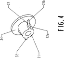
- the cassette 13 and cylindrical element 21 assembly is an exemplary embodiment which can advantageously be replaced by a cylindrical element 21 alone, as shown in FIG. 4, provided with its bearing shoulder 34 of the spring 15 and any means for fixing to the front plate 16.
- the return spring 15 comprises two elastic arms 23 and an internal opening 24 which allows it to be placed on the cylindrical element 21.
- the two elastic arms 23 are raised relative to the central part which has the interior opening, so as to bear at two points by their ends on the shutter 14.
- the shutter 14 has a substantially annular central part 25 and two arms 26 which each carry at their end a stud 27 corresponding in position and in size to the current distribution cells 12 and to the openings 17 of the element 11.
- the central part 25 has a circular opening 28 and two diametrically opposite notches 29.
- the circular opening 28 makes it possible to adapt the shutter to the cylindrical element 21.
- the two notches 29 are arranged to cooperate with the helical ramps 22 which have the form of protruding bulges. It is obvious that if the ramps are in the form of hollow grooves, the notches 29 are replaced by two lugs which penetrate into said grooves and guide them during movement of the shutter.
- the front faceplate 16 has the form of a quadrangular box provided with an annular rim 30 disposed on its front face which has three circular openings 31 corresponding in position to the three circular openings 20 at the bottom of the cassette 13.
- the shutter 14 is in positive support against the faceplate 16.
- the studs 27, which have a flat or convex front surface, are engaged in the circular openings 31 by virtue of an axial stress exerted by the leaf spring 15.
- the axial stress exerted by the pins of the plug on the studs 27 of the shutter causes displacement helical shutter, that is to say a combination of a movement in axial translation and a rotation about the axis. This movement allows the shutter to be retracted and the openings giving access to the current distribution cells to be released.
- FIGS. 3A, 3B, 3C, 3D and 3E The different phases of this plug-in and the movements of the shutter resulting from this plug-in are illustrated in FIGS. 3A, 3B, 3C, 3D and 3E.
- FIG. 3A shows the plug 32 in the approach phase of the front faceplate 16. The shutter 14 is in place and the circular openings 31 are closed by the studs.
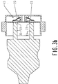
- FIG. 3B shows the plug 32 in a position in which the ends of its pins 33 are in contact with the studs 27.
- the arms 23 of the spring 15 bear against the shutter 14 and exert a constraint which keeps the studs in the openings of the faceplate.
- FIG. 3C shows the plug 32 in an intermediate position in which the thrust exerted by the pins 33 is greater than the force exerted by the spring 15 on the shutter 14.
- the studs 27 begin to emerge from the openings of the faceplate.
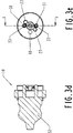
- Figure 3D shows the plug 32 fully engaged in the socket 10. The studs are retracted. The position
- this assembly constitutes a kind of rocker which prevents the introduction of a single rod in the direction of a single cell if a thrust identical to that exerted by this rod on one of the pads 27 is not exerted simultaneously on the other pad.
- the tilting caused in the case of the introduction of a single rod causes the other stud to penetrate into the corresponding opening 31 of the faceplate and blocks the shutter in the rest position, thus preventing access to the cells. Therefore, the leaf spring constitutes a safety device preventing any access to the cells by means of an element other than the pins of a socket outlet.
- FIG. 4 represents a perspective view of the cylindrical element 21 and in particular of the guide ramps 22.
- the ramps comprise a first section 22a parallel to the axis of the base and a second section 22b inclined relative to to this axis.
- the first section makes it possible to release the studs 27 from the openings 31 during the insertion of the pins of a plug and the second section generates the rotational movement necessary to laterally move these studs from the path followed by these pins.
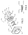
- FIG. 5 shows another embodiment of a socket outlet, which differs from that described above in that it is designed for a three-prong plug.
- This base 10a is composed as before of an element 11a for supporting the cells of current distribution 12a, a cassette 13a for mounting a shutter 14a, a return spring 15a and a faceplate 16a.
- the support 11a is provided with three circular openings 17a and a ground plug 18a.
- the cassette is provided with four circular openings 20a.
- the shutter is equipped with three arms 26a which each carry a stud 27a corresponding to an opening 31a of the faceplate 16a.
- the return spring 15a has three arms 23a which bear on the three arms 26a of the shutter 14a.
- the base is intended either for a keyed socket, one of the three openings being reserved for a keying plug, the other two for current distribution, or for a three-phase socket.
- an O-ring 40 is interposed between the faceplate 16 or 16a and the shutter 14 or 14a to ensure a sealed closure of the openings 31, by means of the studs 27 of the shutter 14 or 14a , taking advantage of the spring bearing force 15 or 15a.
Landscapes
- Connector Housings Or Holding Contact Members (AREA)
Abstract
Description
- La présente invention concerne un socle de prise de courant comportant un élément de support pour des alvéoles de distribution de courant, un plastron frontal agencé pour recevoir une fiche d'un équipement électrique, un élément cylindrique disposé entre ledit élément de support et ledit plastron frontal et supportant un obturateur escamotable conçu pour occuper une position de repos dans laquelle il obture des ouvertures ménagées dans le plastron frontal et prévues pour donner accès auxdits alvéoles de distribution de courant, et une position retirée dans laquelle il libère lesdites ouvertures.
- La présente invention se propose de réaliser un socle de prise de courant qui garantit une obturation efficace des ouvertures de passage vers les alvéoles de contact et qui présente en outre une sécurité supplémentaire due au fait que ladite obturation est maintenue si toutes les broches ne sont pas introduites simultanément dans les ouvertures correspondantes.
- Ces buts sont atteints par le socle de prise de courant selon l'invention, caractérisé en ce que :
- le socle comporte un ressort indépendant, monté sur ledit élément cylindrique pour solliciter l'obturateur en appui contre la face arrière du plastron,
- une rampe de guidage est agencée sur ledit élément cylindrique pour coopérer avec une ouverture circulaire de l'obturateur, ladite rampe étant conformée pour générer un mouvement combiné de translation axiale et de rotation de l'oburateur autour de l'axe dudit élément cylindrique.
- Selon un premier mode de réalisation, ces rampes comportent un premier tronçon sensiblement parallèle à l'axe de l'élément cylindrique pour permettre un dégagement des plots de l'obturateur partiellement engagés dans les ouvertures du plastron frontal et un deuxième tronçon incliné par rapport à cet axe pour générer une rotation de l'obturateur autour dudit axe.
- La présente invention et ses principaux avantages seront mieux compris en référence à la description d'une forme de réalisation préférée et aux dessins annexés donnés à titre d'exemple non limitatifs dans lesquels :
- la figure 1 représente une vue en perspective éclatée d'une première forme de réalisation du socle de prise de courant selon l'invention,
- la figure 2 représente une vue en perspective partiellement coupée du socle de la figure 1,
- les figures 3A, 3B, 3C, 3D et 3E illustrent les phases d'embrochage d'une fiche dans le socle de prise de courant selon les figures 1 et 2,
- la figure 4 représente une vue en perspective de l'élément cylindrique de la cassette de la prise de courant selon les figures précédentes,
- la figure 5 est une vue similaire à celle de la figure 1 représentant une autre forme de réalisation d'un socle de prise de courant selon l'invention, et
- la figure 6 représente une vue partielle illustrant une variante dans laquelle l'obturateur est pourvu d'un joint d'étanchéité.
- En référence aux figures, et en particulier à la figure 1 qui montre le socle en perspective éclatée et à la figure 2 qui le représente assemblé mais partiellement coupé, le socle de prise de courant 10 représenté se compose principalement d'un élément 11 de support des alvéoles de distribution de courant 12, d'une cassette 13 de montage d'un obturateur 14, d'un ressort de rappel 15 du type à lame, qui est agencé pour assurer une contrainte axiale sur l'obturateur, et d'un plastron frontal 16, monté à l'avant du socle de prise de courant 10.
- L'élément 11 de support des alvéoles 12 est une pièce en matière synthétique moulée, par exemple de section circulaire comportant, dans la forme de réalisation représentée, deux ouvertures circulaires 17 débouchant dans les alvéoles de distribution de courant 12, et une fiche de terre 18 de forme cylindrique disposée perpendiculairement sur la façe frontale dudit élément 11.
- La cassette 13 est également une pièce en matière synthétique moulée comportant un fond circulaire 19 entouré d'un rebord sensiblement perpendiculaire à ce fond. Le diamètre du fond circulaire est approximativement égal au diamètre de l'élément 11 de support des alvéoles. Ce fond comporte trois ouvertures circulaires 20 respectivement destinées au passage des deux broches de distribution 33 de courant d'une fiche 32 et de la broche de terre 18. En son centre, le fond circulaire 19 porte un élément cylindrique 21 pourvu d'au moins une et de préférence deux rampes de guidage 22 hélicoïdales ou inclinées par rapport à l'axe dudit plot. Ces rampes, qui peuvent se présenter sous la forme de bourrelets protubérants ou sous celle de gorges creuses, sont agencées pour coopérer avec l'obturateur 14 pour transformer une poussée axiale sur ce dernier en un mouvement combiné de translation axiale et de rotation autour de l'axe de l'élément cylindrique 21. Le nombre de rampes est avantageusement de deux, mais ce nombre pourrait être réduit à un ou augmenté à trois ou quatre.
- L'ensemble cassette 13 et élément cylindrique 21 est un exemple de réalisation qui peut être avantageusement remplacé par un élément cylindrique 21 seul, tel que représenté en figure 4, muni de son épaulement d'appui 34 du ressort 15 et d'un quelconque moyen de fixation au plastron frontal 16.
- Le ressort de rappel 15 comporte deux bras élastiques 23 et une ouverture intérieure 24 qui autorise sa mise en place sur l'élément cylindrique 21.
- Les deux bras élastiques 23 sont relevés par rapport à la partie centrale qui comporte l'ouverture intérieure, de manière à prendre appui en deux points par leur extrémité sur l'obturateur 14.
- L'obturateur 14 comporte une partie centrale 25 sensiblement annulaire et deux bras 26 qui portent chacun à leur extrémité un plot 27 correspondant en position et en dimension aux alvéoles de distribution de courant 12 et aux ouvertures 17 de l'élément 11. La partie centrale 25 comporte une ouverture circulaire 28 et deux encoches 29 diamétralement opposées. L'ouverture circulaire 28 permet d'adapter l'obturateur sur l'élément cylindrique 21. Les deux encoches 29 sont agencées pour coopérer avec les rampes hélicoïdales 22 qui ont la forme de bourrelets protubérants. Il est évident que si les rampes se présentent sous la forme de gorges creuses, les encoches 29 sont remplacées par deux ergots qui pénètrent dans lesdites gorges et assurent leur guidage lors d'un déplacement de l'obturateur.
- Le plastron frontal 16 a la forme d'un boîtier quadrangulaire pourvu d'un rebord annulaire 30 disposé sur sa face frontale qui comporte trois ouvertures circulaires 31 correspondant en position aux trois ouvertures circulaires 20 du fond de la cassette 13.
- Au repos, l'obturateur 14 est en appui positif contre le plastron 16. Les plots 27, qui présentent une surface frontale plane ou convexe, sont engagés dans les ouvertures circulaires 31 grâce à une contrainte axiale exercée par le ressort à lame 15. Lors de l'embrochage de la fiche 32 dans le socle de la prise de courant, la contrainte axiale exercée par les broches de la fiche sur les plots 27 de l'obturateur entraîne un déplacement hélicoïdal de l'obturateur, c'est-à-dire une combinaison d'un mouvement en translation axiale et d'une rotation autour de l'axe. Ce déplacement permet d'escamoter l'obturateur et de dégager les ouvertures donnant accès aux alvéoles de distribution du courant.
- Les différentes phases de cet embrochage et les mouvements de l'obturateur résultant de cet embrochage sont illustrés par les figures 3A, 3B, 3C, 3D et 3E. La figure 3A montre la fiche 32 en phase d'approche du plastron frontal 16. L'obturateur 14 est en place et les ouvertures circulaires 31 sont fermées par les plots 27. La figure 3B montre la fiche 32 dans une position dans laquelle les extrémités de ses broches 33 sont en contact avec les plots 27. Les bras 23 du ressort 15 sont en appui contre l'obturateur 14 et exercent une contrainte qui maintient les plots dans les ouvertures du plastron. La figure 3C montre la fiche 32 dans une position intermédiaire dans laquelle la poussée exercée par les broches 33 est supérieure à la force exercée par le ressort 15 sur l'obturateur 14. Les plots 27 commencent à se dégager des ouvertures du plastron. La figure 3D montre la fiche 32 complètement engagée dans la prise 10. Les plots se sont escamotés. La position de l'obturateur 14, et plus particulièrement de ses plots 27, est représentée par la figure 3E.
- En raison de la géométrie du ressort, et en particulier grâce au fait que les bras 23 sont relevés par rapport à la partie centrale, cet ensemble constitue une sorte de bascule qui empêche l'introduction d'une tige unique en direction d'un seul alvéole si une poussée identique à celle exercée par cette tige sur un des plots 27 n'est pas exercée simultanément sur l'autre plot. Le basculement provoqué dans le cas de l'introduction d'une tige unique fait pénétrer l'autre plot dans l'ouverture correspondante 31 du plastron et bloque l'obturateur en position de repos, empêchant ainsi l'accès aux alvéoles. De ce fait, le ressort à lame constitue un dispositif de sécurité interdisant tout accès aux alvéoles au moyen d'un élément autre que les broches d'une fiche de prise de courant.
- La figure 4 représente une vue en perspective de l'élément cylindrique 21 et en particulier des rampes de guidage 22. Dans la réalisation représentée, les rampes comportent un premier tronçon 22a parallèle à l'axe du socle et un deuxième tronçon 22b incliné par rapport à cet axe. Le premier tronçon permet de dégager les plots 27 des ouvertures 31 lors de l'introduction des broches d'une fiche et le deuxième tronçon génère le mouvement de rotation nécessaire pour déplacer latéralement ces plots de la trajectoire suivie par ces broches.
- La figure 5 représente une autre forme de réalisation d'un socle de prise de courant, qui diffère de celle décrite ci-dessus en ce qu'elle est conçue pour une fiche à trois broches. Ce socle 10a se compose comme précédemment d'un élément 11a de support des alvéoles de distribution de courant 12a, d'une cassette 13a de montage d'un obturateur 14a, d'un ressort de rappel 15a et d'un plastron 16a. Le support 11a est pourvu de trois ouvertures circulaires 17a et d'une fiche de terre 18a. La cassette est pourvue de quatre ouvertures circulaires 20a. L'obturateur est équipé de trois bras 26a qui portent chacun un plot 27a correspondant à une ouverture 31a du plastron 16a. Le ressort de rappel 15a a trois bras 23a qui prennent appui sur les trois bras 26a de l'obturateur 14a.
- Dans cette réalisation, le socle est destiné soit à une prise à détrompage, l'une des trois ouvertures étant réservée à une fiche de détrompage, les deux autres à la distribution du courant, soit à une prise triphasée.
- Selon une variante avantageuse représentée par la figure 6, un joint torique 40 est interposé entre le plastron 16 ou 16a et l'obturateur 14 ou 14a pour assurer une fermeture étanche des ouvertures 31, au moyen des plots 27 de l'obturateur 14 ou 14a, profitant de la force d'appui de ressort 15 ou 15a.
Claims (8)
- Socle de prise de courant comportant un élément de support pour des alvéoles de distribution de courant, un plastron frontal agencé pour recevoir une fiche d'un équipement électrique, un élément cylindrique disposé entre ledit élément de support et ledit plastron frontal et supportant un obturateur escamotable conçu pour occuper une position de repos dans laquelle il obture des ouvertures ménagées dans le plastron frontal et prévues pour donner accès auxdits alvéoles de distribution de courant, et une position retirée dans laquelle il libère lesdites ouvertures,
caractérisé en ce que- le socle (10, 10a) comporte un ressort (15, 15a) indépendant, monté sur ledit élément cylindrique (21, 21a) pour solliciter l'obturateur (14, 14a) en appui contre la face arrière du plastron (16, 16a),- une rampe de guidage (22) est agencée sur ledit élément cylindrique pour coopérer avec une ouverture (28) circulaire de l'obturateur, ladite rampe étant conformée pour générer un mouvement combiné de translation axiale et de rotation de l'oburateur autour de l'axe dudit élément cylindrique. - Socle selon la revendication 1, caractérisé en ce que lesdites rampes de guidage (22) ont un premier tronçon (22a, 22c) sensiblement parallèle à l'axe de l'élément cylindrique (21) et un deuxième tronçon (22b, 22d) incliné par rapport à cet axe.
- Socle selon la revendication 1, caractérisé en ce que lesdites rampes de guidage (22) ont au moins partiellement un profil sensiblement hélicoïdal.
- Socle selon la revendication 1, caractérisé en ce que le ressort (15, 15a) est du type à lame et comporte une partie centrale annulaire et au moins deux bras (23; 23a) relevés par rapport à cette partie annulaire.
- Socle selon la revendication 4, caractérisé en ce que le ressort (15, 15a) est agencé pour exercer une force d'appui sur l'obturateur (14, 14a) dans la position de repos.
- Socle selon la revendication 1, caractérisé en ce que l'obturateur (14, 14a) comporte au moins deux bras (26, 26a) munis de plots (27, 27a) disposés à l'extrémité de ces bras, ces plots étant agencés pour s'engager au moins partiellement dans lesdites ouvertures (31, 31a) du plastron.
- Socle selon la revendication 6, caractérisé en ce que lesdits plots (27, 27a) ont une surface plane ou convexe.
- Socle selon la revendication 6, caractérisé en ce qu'il comporte un joint d'étanchéité (40) interposé entre le plastron (16, 16a) et l'obturateur (14, 14a).
Applications Claiming Priority (2)
| Application Number | Priority Date | Filing Date | Title |
|---|---|---|---|
| FR9314274A FR2713022B1 (fr) | 1993-11-24 | 1993-11-24 | Socle de prise de courant avec obturateur escamotable. |
| FR9314274 | 1993-11-24 |
Publications (2)
| Publication Number | Publication Date |
|---|---|
| EP0654857A1 true EP0654857A1 (fr) | 1995-05-24 |
| EP0654857B1 EP0654857B1 (fr) | 1998-02-04 |
Family
ID=9453341
Family Applications (1)
| Application Number | Title | Priority Date | Filing Date |
|---|---|---|---|
| EP19940410102 Expired - Lifetime EP0654857B1 (fr) | 1993-11-24 | 1994-11-18 | Socle de prise de courant avec obturateur escamotable |
Country Status (4)
| Country | Link |
|---|---|
| EP (1) | EP0654857B1 (fr) |
| DE (1) | DE69408411D1 (fr) |
| ES (1) | ES2115182T3 (fr) |
| FR (1) | FR2713022B1 (fr) |
Cited By (2)
| Publication number | Priority date | Publication date | Assignee | Title |
|---|---|---|---|---|
| GB2501454A (en) * | 2011-09-09 | 2013-10-30 | Ifpl Group Ltd | Electrical socket requiring all pins of a plug to be inserted, or which detects a plug pin using radiation |
| EP3352308A1 (fr) * | 2017-01-23 | 2018-07-25 | Berker GmbH & Co. KG | Dispositif de couverture pour prise d'alimentation et prise d'alimentation équipée d'un tel dispositif de couverture |
Citations (3)
| Publication number | Priority date | Publication date | Assignee | Title |
|---|---|---|---|---|
| GB628692A (en) * | 1947-09-10 | 1949-09-02 | Dorman & Smith Ltd | Improvements in and relating to a shutter device for electric socket apparatus |
| FR2271680A1 (en) * | 1974-05-14 | 1975-12-12 | Couqueberg Michel | Plug and socket with safety shutter - has guide slot in plug earth pin rotating shutter to align pin access holes |
| GB2209888A (en) * | 1987-09-16 | 1989-05-24 | Conblock Electrical Ltd | An electrical socket with rotary shutter |
-
1993
- 1993-11-24 FR FR9314274A patent/FR2713022B1/fr not_active Expired - Fee Related
-
1994
- 1994-11-18 EP EP19940410102 patent/EP0654857B1/fr not_active Expired - Lifetime
- 1994-11-18 DE DE69408411T patent/DE69408411D1/de not_active Expired - Lifetime
- 1994-11-18 ES ES94410102T patent/ES2115182T3/es not_active Expired - Lifetime
Patent Citations (3)
| Publication number | Priority date | Publication date | Assignee | Title |
|---|---|---|---|---|
| GB628692A (en) * | 1947-09-10 | 1949-09-02 | Dorman & Smith Ltd | Improvements in and relating to a shutter device for electric socket apparatus |
| FR2271680A1 (en) * | 1974-05-14 | 1975-12-12 | Couqueberg Michel | Plug and socket with safety shutter - has guide slot in plug earth pin rotating shutter to align pin access holes |
| GB2209888A (en) * | 1987-09-16 | 1989-05-24 | Conblock Electrical Ltd | An electrical socket with rotary shutter |
Cited By (5)
| Publication number | Priority date | Publication date | Assignee | Title |
|---|---|---|---|---|
| GB2501454A (en) * | 2011-09-09 | 2013-10-30 | Ifpl Group Ltd | Electrical socket requiring all pins of a plug to be inserted, or which detects a plug pin using radiation |
| GB2501454B (en) * | 2011-09-09 | 2016-06-15 | Ifpl Group Ltd | Electrical socket |
| US9570834B2 (en) | 2011-09-09 | 2017-02-14 | Wunelli Limited | Electrical socket with shutter and retainer arrangement |
| EP3352308A1 (fr) * | 2017-01-23 | 2018-07-25 | Berker GmbH & Co. KG | Dispositif de couverture pour prise d'alimentation et prise d'alimentation équipée d'un tel dispositif de couverture |
| WO2018134282A1 (fr) * | 2017-01-23 | 2018-07-26 | Berker Gmbh & Co. Kg | Dispositif de couverture avant pour prise électrique et prise électrique équipée d'un tel dispositif de couverture avant |
Also Published As
| Publication number | Publication date |
|---|---|
| ES2115182T3 (es) | 1998-06-16 |
| EP0654857B1 (fr) | 1998-02-04 |
| FR2713022B1 (fr) | 1995-12-22 |
| FR2713022A1 (fr) | 1995-06-02 |
| DE69408411D1 (de) | 1998-03-12 |
Similar Documents
| Publication | Publication Date | Title |
|---|---|---|
| EP0528735A1 (fr) | Dispositif sélectif de connexion électrique muni d'un disque de sécurité et d'un disque complémentaire | |
| FR2475812A1 (fr) | Organe de connexion electrique comportant un mecanisme perfectionne s'opposant au desassemblage | |
| FR2497609A1 (fr) | Dispositif de connexion du type a pousser-tirer | |
| FR2694138A1 (fr) | Système d'adaptation entre une fiche d'antenne et un socle d'un radiotéléphone. | |
| EP0505256B1 (fr) | Adaptateur en deux parties pour appareil électrique à brancher par une fiche sur un socle de prise de courant | |
| EP0112258B1 (fr) | Socle pour prise de courant de sécurité notamment pour atmosphère explosive | |
| EP0986842B1 (fr) | Bague de reperage de la tension d'emploi d'un element de connexion electrique | |
| EP0763875B1 (fr) | Prise électrique à détrompage | |
| FR2518322A2 (fr) | Dispositif de connexion du type a " pousser-tirer " | |
| EP1318569B1 (fr) | Socle de prise de courant à obturateur d'alvéoles et gamme comprenant un tel socle | |
| FR2584873A1 (fr) | Systeme de raccordement electrique pour un reseau specifique de distribution de courant, et adaptateur pour fiche de raccordement electrique et socle de prise de courant correspondants | |
| EP0654857B1 (fr) | Socle de prise de courant avec obturateur escamotable | |
| EP0401097B1 (fr) | Dispositif de verrouillage d'un connecteur | |
| EP3840136B1 (fr) | Mecanisme d'appareillage electrique, ensemble electrique et appareillage electrique associes | |
| EP0654858B1 (fr) | Socle de prise de courant à détrompage | |
| FR2684241A1 (fr) | Dispositif de connexion de securite pour branchement electrique. | |
| FR2924535A1 (fr) | Appareillage electrique encastre a connexion rapide | |
| FR2974457A1 (fr) | Bloc multi-appareillages equipe d'un connecteur mobile en translation | |
| FR2974456A1 (fr) | Bloc multi-appareillages equipe de moyens de fixation a une paroi | |
| FR3165532A1 (fr) | Appareillage électrique à borne de connexion automatique | |
| EP0680109A1 (fr) | Embase d'antenne ayant un écrou porté par un support muni de moyens de montage unidirectionnel | |
| EP0642194A1 (fr) | Connecteur électrique coaxial à verrouillage par vissage | |
| EP0345189A1 (fr) | Connecteur électrique | |
| WO2024028026A1 (fr) | Dispositif d'isolation électrique pour barre d'interconnexion | |
| FR2680607A1 (fr) | Dispositif selectif de connexion electrique muni d'un disque de securite. |
Legal Events
| Date | Code | Title | Description |
|---|---|---|---|
| PUAI | Public reference made under article 153(3) epc to a published international application that has entered the european phase |
Free format text: ORIGINAL CODE: 0009012 |
|
| AK | Designated contracting states |
Kind code of ref document: A1 Designated state(s): BE CH DE ES GB IT LI SE |
|
| 17P | Request for examination filed |
Effective date: 19951110 |
|
| 17Q | First examination report despatched |
Effective date: 19960410 |
|
| GRAG | Despatch of communication of intention to grant |
Free format text: ORIGINAL CODE: EPIDOS AGRA |
|
| GRAG | Despatch of communication of intention to grant |
Free format text: ORIGINAL CODE: EPIDOS AGRA |
|
| GRAH | Despatch of communication of intention to grant a patent |
Free format text: ORIGINAL CODE: EPIDOS IGRA |
|
| GRAH | Despatch of communication of intention to grant a patent |
Free format text: ORIGINAL CODE: EPIDOS IGRA |
|
| GRAA | (expected) grant |
Free format text: ORIGINAL CODE: 0009210 |
|
| AK | Designated contracting states |
Kind code of ref document: B1 Designated state(s): BE CH DE ES GB IT LI SE |
|
| PG25 | Lapsed in a contracting state [announced via postgrant information from national office to epo] |
Ref country code: IT Free format text: LAPSE BECAUSE OF FAILURE TO SUBMIT A TRANSLATION OF THE DESCRIPTION OR TO PAY THE FEE WITHIN THE PRESCRIBED TIME-LIMIT;WARNING: LAPSES OF ITALIAN PATENTS WITH EFFECTIVE DATE BEFORE 2007 MAY HAVE OCCURRED AT ANY TIME BEFORE 2007. THE CORRECT EFFECTIVE DATE MAY BE DIFFERENT FROM THE ONE RECORDED. Effective date: 19980204 Ref country code: GB Free format text: LAPSE BECAUSE OF FAILURE TO SUBMIT A TRANSLATION OF THE DESCRIPTION OR TO PAY THE FEE WITHIN THE PRESCRIBED TIME-LIMIT Effective date: 19980204 |
|
| REG | Reference to a national code |
Ref country code: CH Ref legal event code: EP |
|
| REF | Corresponds to: |
Ref document number: 69408411 Country of ref document: DE Date of ref document: 19980312 |
|
| PG25 | Lapsed in a contracting state [announced via postgrant information from national office to epo] |
Ref country code: SE Free format text: LAPSE BECAUSE OF FAILURE TO SUBMIT A TRANSLATION OF THE DESCRIPTION OR TO PAY THE FEE WITHIN THE PRESCRIBED TIME-LIMIT Effective date: 19980504 |
|
| PG25 | Lapsed in a contracting state [announced via postgrant information from national office to epo] |
Ref country code: DE Free format text: LAPSE BECAUSE OF FAILURE TO SUBMIT A TRANSLATION OF THE DESCRIPTION OR TO PAY THE FEE WITHIN THE PRESCRIBED TIME-LIMIT Effective date: 19980505 |
|
| REG | Reference to a national code |
Ref country code: ES Ref legal event code: FG2A Ref document number: 2115182 Country of ref document: ES Kind code of ref document: T3 |
|
| GBV | Gb: ep patent (uk) treated as always having been void in accordance with gb section 77(7)/1977 [no translation filed] |
Effective date: 19980204 |
|
| PG25 | Lapsed in a contracting state [announced via postgrant information from national office to epo] |
Ref country code: BE Free format text: LAPSE BECAUSE OF NON-PAYMENT OF DUE FEES Effective date: 19981130 |
|
| PGFP | Annual fee paid to national office [announced via postgrant information from national office to epo] |
Ref country code: CH Payment date: 19981210 Year of fee payment: 5 |
|
| PLBE | No opposition filed within time limit |
Free format text: ORIGINAL CODE: 0009261 |
|
| STAA | Information on the status of an ep patent application or granted ep patent |
Free format text: STATUS: NO OPPOSITION FILED WITHIN TIME LIMIT |
|
| 26N | No opposition filed | ||
| BERE | Be: lapsed |
Owner name: S.A. SCHNEIDER ELECTRIC Effective date: 19981130 |
|
| PG25 | Lapsed in a contracting state [announced via postgrant information from national office to epo] |
Ref country code: LI Free format text: LAPSE BECAUSE OF NON-PAYMENT OF DUE FEES Effective date: 19991130 Ref country code: CH Free format text: LAPSE BECAUSE OF NON-PAYMENT OF DUE FEES Effective date: 19991130 |
|
| PGFP | Annual fee paid to national office [announced via postgrant information from national office to epo] |
Ref country code: ES Payment date: 19991130 Year of fee payment: 6 |
|
| REG | Reference to a national code |
Ref country code: CH Ref legal event code: PL |
|
| PG25 | Lapsed in a contracting state [announced via postgrant information from national office to epo] |
Ref country code: ES Free format text: LAPSE BECAUSE OF NON-PAYMENT OF DUE FEES Effective date: 20001119 |
|
| REG | Reference to a national code |
Ref country code: ES Ref legal event code: FD2A Effective date: 20011214 |