EP0654891A1 - Elektronische Steuervorrichtung eines 2-Klemmen-Gleichstrommotors, für ein hin- und herbewegbares Antriebsystem und Anwendung für das Scheibenwischersystem eines Fahrzeugs - Google Patents
Elektronische Steuervorrichtung eines 2-Klemmen-Gleichstrommotors, für ein hin- und herbewegbares Antriebsystem und Anwendung für das Scheibenwischersystem eines Fahrzeugs Download PDFInfo
- Publication number
- EP0654891A1 EP0654891A1 EP94118293A EP94118293A EP0654891A1 EP 0654891 A1 EP0654891 A1 EP 0654891A1 EP 94118293 A EP94118293 A EP 94118293A EP 94118293 A EP94118293 A EP 94118293A EP 0654891 A1 EP0654891 A1 EP 0654891A1
- Authority
- EP
- European Patent Office
- Prior art keywords
- motor
- circuit
- switch
- control
- controlled switch
- Prior art date
- Legal status (The legal status is an assumption and is not a legal conclusion. Google has not performed a legal analysis and makes no representation as to the accuracy of the status listed.)
- Withdrawn
Links
- 238000001514 detection method Methods 0.000 claims description 10
- 230000006870 function Effects 0.000 claims description 9
- 230000008859 change Effects 0.000 claims description 7
- 230000005669 field effect Effects 0.000 claims description 3
- 230000004044 response Effects 0.000 claims description 3
- 238000010586 diagram Methods 0.000 description 17
- 230000001133 acceleration Effects 0.000 description 3
- 230000005534 acoustic noise Effects 0.000 description 3
- 230000032683 aging Effects 0.000 description 2
- 230000008901 benefit Effects 0.000 description 2
- 239000003990 capacitor Substances 0.000 description 2
- 238000001914 filtration Methods 0.000 description 2
- 239000011521 glass Substances 0.000 description 2
- 230000010355 oscillation Effects 0.000 description 2
- 238000012360 testing method Methods 0.000 description 2
- 230000007704 transition Effects 0.000 description 2
- 230000004913 activation Effects 0.000 description 1
- 230000001174 ascending effect Effects 0.000 description 1
- 239000006185 dispersion Substances 0.000 description 1
- 230000000694 effects Effects 0.000 description 1
- 230000005284 excitation Effects 0.000 description 1
- 238000002474 experimental method Methods 0.000 description 1
- 238000005259 measurement Methods 0.000 description 1
- 230000009467 reduction Effects 0.000 description 1
- 230000000630 rising effect Effects 0.000 description 1
Images


Classifications
-
- B—PERFORMING OPERATIONS; TRANSPORTING
- B60—VEHICLES IN GENERAL
- B60S—SERVICING, CLEANING, REPAIRING, SUPPORTING, LIFTING, OR MANOEUVRING OF VEHICLES, NOT OTHERWISE PROVIDED FOR
- B60S1/00—Cleaning of vehicles
- B60S1/02—Cleaning windscreens, windows or optical devices
- B60S1/04—Wipers or the like, e.g. scrapers
- B60S1/06—Wipers or the like, e.g. scrapers characterised by the drive
- B60S1/08—Wipers or the like, e.g. scrapers characterised by the drive electrically driven
-
- H—ELECTRICITY
- H02—GENERATION; CONVERSION OR DISTRIBUTION OF ELECTRIC POWER
- H02P—CONTROL OR REGULATION OF ELECTRIC MOTORS, ELECTRIC GENERATORS OR DYNAMO-ELECTRIC CONVERTERS; CONTROLLING TRANSFORMERS, REACTORS OR CHOKE COILS
- H02P7/00—Arrangements for regulating or controlling the speed or torque of electric DC motors
- H02P7/03—Arrangements for regulating or controlling the speed or torque of electric DC motors for controlling the direction of rotation of DC motors
- H02P7/05—Arrangements for regulating or controlling the speed or torque of electric DC motors for controlling the direction of rotation of DC motors by means of electronic switching
Definitions
- the present invention relates to an electronic device for controlling a direct current electric motor.
- a motor serves as a drive motor and operates back and forth.
- Such a motor is applied in a wiping system and drives a wiping system in an oscillating movement. It generates significant acoustic noise due to the change of direction in the scanning movement.
- the present invention relates to an electronic device for controlling a two-terminal direct current electric motor.
- a motor is used for driving running back and forth in particular from a wiping system.
- the invention also relates to a drive system such as a wiping system for a vehicle window.
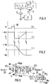
- FIG. 1 there is shown a block diagram of a preferred embodiment of the invention.
- the electric motor 1 is provided with two brushes, which are electrically connected to a DC power supply network by terminals 2 and 3.
- the DC power supply is produced by a source 4, which depending on the position of the system drive not shown in the drawings, allows to reverse the polarity applied to the motor terminals.
- the source 4 is connected on the one hand to the terminal 2 of the motor and on the other hand to a terminal 7 of a circuit consisting mainly of a controllable switch 5.
- the other terminal 6 of the controllable switch 5 is connected to the free terminal 3 of the electric motor 1.
- the drive system includes means for detecting a command to reverse the direction of rotation of the motor.
- the means 9 can be constituted by two end-of-travel sensors arranged on either side of the end points of the oscillation travel of the drive system in its back and forth movement.
- the detection signals are transmitted by an input 10 to a control circuit 12 which therefore receives the detection signal and produces in response a control signal.
- the control signal from the control device 12 is transmitted by a link 11 to the control terminal 8 of the controllable switch 5.
- the means for detecting a command for reversing the direction of rotation of the motor 10 produces a pulse 20 which informs the electronic control device that the direction of rotation of the motor must be reversed.
- the slot 20 of FIG. 2a is used both by the line 10 to validate the control device 12 and on the other hand makes it possible to configure the DC power source 4 in the opposite polarity when this is necessary as is the case. will see further.
- control circuit 12 produces a control signal 11 (shown in FIG. 2b) which enables the controllable switch 5 to be opened on date t0.
- FIG 2b there is shown the timing diagram of the control signal 11 of the controllable switch 5 according to the operation of the invention at the date t0, the voltage across the motor which was equal to + Val, which represents the voltage d 'power supply, drops to value 0 due to the opening of the component. Then for a period going up to the date t1, the voltage remains zero then the control device produces a control signal 11, in the form of an ascending ramp, so as to return to the value + Val on the date t2.
- the motor can behave optimally by adjusting both the duration of cancellation of the voltage at the date t1 and the slope of the ramp, that is to say the duration t2-t1 so as to optimize the behavior of the drive system back and forth, in particular from the point of view of the acoustic noise of overturning.
- the inventors have found that the noise of reversal of a wiping system was mainly due to the phase of re-acceleration of the movement after slowing down and that the slowing phase only required a cancellation of the tension rather than a control enslaved, more complex to achieve.
- FIG 3 there is shown a preferred embodiment of the circuit 4 for producing the reversal of the movement of the wiping system.
- the circuit 4 consists of two electromechanical relays 30 and 31 which have two contacts and a movable finger.
- the relay 30 comprises a movable finger connected to a contact 34-1, connected to the terminal 2 of the motor 1, while the relay 31 comprises a movable finger connected to a terminal 34-2 connected to the terminal 3 of the motor 1.
- the terminals 32-1 and 32-2 of the relays 30 and 31 are connected to the positive voltage + Vbat via a relay KG of continuous operation while the terminals 33-1 and 33-2 are connected via the controlled switch 5 to the -Vbat polarity of the battery.
- the relays 30 and 31 respectively comprise control terminals 35-1 and 35-2 which control electromagnetic coils 36-1 and 36-2 of change of contact.
- the relays can be of the bistable type.
- the motor 1 is mechanically connected to a pair of wipers mounted on a mobile assembly 37, the wipers being 38-1 and 38-2 and which are both connected to a positive voltage such as the + of the battery + Vbat.
- Two tracks 39-1 and 39-2 respectively are installed in the limit switch detection means 9.
- Two access terminals respectively CFC1 and CFC2 are taken on tracks 39-1 and 39-2 respectively and are connected by the optionally through a suitable control circuit at the input terminals 35-1 and 35-2 respectively to allow the reversal of the direction of rotation of the motor as a function of the position reached by the moving element 7 connected to the movement of the wiping system in particular or any other actuation system used in the invention.
- the motor is mechanically connected to tracks 39-1 and 39-2.
- the wipers 38-1 and 38-2 are mounted on the support 37 which is fixed.
- the signals CFC1 and CFC2 are taken on the wipers 38-1 and 38-2.
- FIG. 4 six timing diagrams for controlling the relays in FIG. 3 have been represented.
- FIG. 4a the request for continuous operation has been shown which has a niche shape during the whole time of the continuous operation of the actuating system. , and which has a rising edge 40 when the switch KG is closed by the user who requests the system to be started.
- the limit switch 1 constituted by track 39-1, is not connected to the potential + Vbat whereas in FIG. 4e it is noted that the limit switch 2, is connected at + Vbat as shown in the right part of the representative drawing of FIG. 3 for the limit switch 9.
- the relay 1 switches to position 32-1 which is represented by a slot 41.
- the relay 2, referenced 31 in FIG. 3 has a state where it is on the contact 33-2.
- Current flows through the motor in a first direction which drives the motor in a first direction of rotation.
- the mobile carriage 37 moves in the limit switch, it leaves the outputs CFC1 and CFC2 at the voltage + Vbat, as shown in the timing diagrams of Figures 4d and 4e respectively.
- zone 42 corresponds to a short circuit in the motor. This short circuit produces braking.
- the wiping system control or command circuit brings 32 -2 back into contact with 34-2, which controls the motor in the other direction. Therefore, as represented by the zone 42 on the diagram of FIG. 4e, the limit switch detection signal on the CFC2 limit switch returns to 0, which allows via the relay control circuit to reverse the direction of operation of relay 31, which goes back into a state 32-2 of 34-2 as shown in the diagram in Figure 4c.
- FIG 5 there is shown schematically a preferred embodiment of the invention.
- the circuit 4 for reversing the direction of rotation of the motor has been shown diagrammatically and will not be described further.
- the coils relays 30 and 31 (not shown in Figure 5) are controlled by an output 51 of a control circuit 50 constituted in particular by a microcontroller or by a specialized integrated circuit.
- the microcontroller or control circuit 50 has a series of input ports 52 which in particular receive the vehicle start-up information + APC and the control information from the commodo, in particular the continuous start-up MCO, the intermittence Int and LV windshield washer etc.
- control circuit 50 has input ports 53 connected to the limit switch detection signals CFC1 and CFC2 described with the aid of FIGS. 3 and 4.
- the controllable switch 5 mainly consists of a field effect transistor T whose drain-source circuit is mounted in parallel with a Zener Z diode.
- the drain of transistor T is connected in common with the cathode of the Zener Z diode at common point of low potential of the supply circuit 4.
- the source of the transistor T and the anode of the Zener diode Z are connected to ground, that is to say to the negative polarity of the battery.
- the transistor T is controlled by means of a circuit P constituted by an operational amplifier connected by means of its positive input terminal on the one hand to the drain of the transistor T via a resistor R1 and on the other hand to ground via a resistor R2.
- the - terminal of the amplifier P is connected directly to an output port 54 of the control circuit.
- the output port 54 is programmed so as to generate the waveform shown in FIG. 2b according to the detection of the limit switches.
- the field effect transistor is chosen to be of MOS type so as to limit the voltage drop and facilitate control of the switch.
- the transistor T is of the bipolar type.
- the circuit for control 50 when the limit switch information CFC1 or CFC2 changes to the value 0, the circuit for control 50 produces on the output port 54 a falling edge, which allows via the pilot circuit P to open the transistor T. The current in the motor is canceled and the motor goes into freewheeling operation. The friction of the actuating system, like the wiping system, reduces the speed until the engine stops. Due to the opening of the transistor T, the output port 51 of the control circuit 50 produces the control signals of the coils of the relays 30 and 31. It is possible to freely switch the two relays at any time during that the transistor T is open, since the negative polarity is no longer accessible by the motor 1. It is an advantage of the present invention to (thus imitate the risks of ignition caused by setting the negative polarity of the one of the terminals when the other terminal remains at the positive voltage.
- the reestablishment of the command is done by a pre-programmed ramp whose shape is produced in the form of a table of values which allows a digital analog converter connected to the output port 54 in the control circuit 50 for generating a waveform, in the form of an increasing ramp, connected to the negative input terminal of the amplifier P of the controllable switch 5.
- the switching takes place with a servo-control and the voltage at the terminals of the transistor is applied to the positive input of the operational amplifier P. This control makes it possible to gradually lower the voltage between drain and source according to the predetermined ramp.
- the transistor T works in linear mode.
- restart time t1 is prerecorded and sized according to the system used.
- time t2 of full conduction is preprogrammed and depends on the system and these initial settings.
- the circuit 56 for measuring the voltage at the source and drain terminals of the transistor T consists mainly of a comparator 57, a first input + of which is connected by a divider bridge 58a, 58b to the source terminal of transistor T.
- a filtering capacitor 58c is provided.
- the negative input terminal of the amplifier 57 is connected to a voltage + VCC via a second divider bridge 59a, 59b, and is optionally also provided with a filtering capacitor 59c.
- the output terminal S57 of the amplifier 57 mounted as a voltage comparator by the feedback resistor R57, is connected to the input of an input port 55 of the control circuit 50, which generates a control signal (not shown) which makes it possible to start the generation of the conduction increase ramp and to control it as a function of the instantaneous measured voltage.
- the start date of the ramp depends on the circumstances.
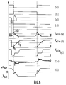
- FIG. 6 the timing diagrams measured on the assembly of FIG. 5 have been represented.
- FIG. 6a represents the operation of the relay 30, while FIG. 6b represents the operation of the relay 31.
- the state transition of operation is done in phase opposition in the preferred embodiment. This phase transition takes place on the date t1 which follows the date t0 of end-of-travel detection CFC1 (see FIG. 6c).
- the output port 54 produces on the date t1 a conduction ramp which lasts at least until the instant t2 at which the transistor T is fully conductive and has a substantially zero voltage.
- the inventors have found that the distance traveled by the wiper blades during the phase when the motor is not supplied varies markedly as a function of friction on the swept glass, or as a function of the supply voltage of the control.
- the friction varies greatly depending on the state of humidity and wettability of the surface of the glass, while the supply voltage of the control depends for example on the voltage of the battery which we know that in the automotive environment it may be subject to sudden variations.
- the inventors have used in the integrated circuit which produces the control circuit 50, a circuit for counting the time elapsed between the last two pieces of information delivered by the limit switches .
- the time counted by the counter implemented in this integrated circuit is directly linked to friction and to the supply voltage.
- the value of the delay time Te makes it possible to address a table of values of a delay time Tr which is intended to be added to the limit switch information CFC1 and CFC2 delivered by the limit switches to produce information on the opening of the transistors T and the triggering of the change of direction of operation by inverting the state of the relays.
- the delay time Tr introduced is zero, when the measured time Te increases the delay Tr also increases. During this delay, the motor power control remains maximum and the motor can thus travel a greater angle than that which would be traveled in the absence of delay.
- the invention makes it possible to solve the whole of the problem posed and appreciably improves the wiping function.
Landscapes
- Engineering & Computer Science (AREA)
- Power Engineering (AREA)
- Mechanical Engineering (AREA)
- Control Of Direct Current Motors (AREA)
Applications Claiming Priority (2)
| Application Number | Priority Date | Filing Date | Title |
|---|---|---|---|
| FR9313830A FR2712749B1 (fr) | 1993-11-19 | 1993-11-19 | Dispositif électronique de commande d'un moteur électrique à courant continu, pour système d'entraînement fonctionnant en va et vient et application à un système d'essuyage de vitre de véhicule. |
| FR9313830 | 1993-11-19 |
Publications (1)
| Publication Number | Publication Date |
|---|---|
| EP0654891A1 true EP0654891A1 (de) | 1995-05-24 |
Family
ID=9453023
Family Applications (1)
| Application Number | Title | Priority Date | Filing Date |
|---|---|---|---|
| EP94118293A Withdrawn EP0654891A1 (de) | 1993-11-19 | 1994-11-21 | Elektronische Steuervorrichtung eines 2-Klemmen-Gleichstrommotors, für ein hin- und herbewegbares Antriebsystem und Anwendung für das Scheibenwischersystem eines Fahrzeugs |
Country Status (3)
| Country | Link |
|---|---|
| US (1) | US5512807A (de) |
| EP (1) | EP0654891A1 (de) |
| FR (1) | FR2712749B1 (de) |
Cited By (2)
| Publication number | Priority date | Publication date | Assignee | Title |
|---|---|---|---|---|
| WO2008049536A1 (de) * | 2006-10-24 | 2008-05-02 | Valeo Systèmes d'Essuyage | Verfahren zum steuern der bewegung eines wischarmes einer wischanlage für fahrzeugscheiben |
| EP2607186A3 (de) * | 2011-12-21 | 2018-05-02 | Robert Bosch Gmbh | Verfahren zum Betreiben einer Scheibenwischeinrichtung sowie Scheibenwischeinrichtung |
Families Citing this family (1)
| Publication number | Priority date | Publication date | Assignee | Title |
|---|---|---|---|---|
| JP6610298B2 (ja) * | 2016-01-29 | 2019-11-27 | 株式会社デンソー | 車両用ワイパ制御装置及び車両用ワイパ制御プログラム |
Citations (6)
| Publication number | Priority date | Publication date | Assignee | Title |
|---|---|---|---|---|
| EP0034822A1 (de) * | 1980-02-21 | 1981-09-02 | Black & Decker Inc. | Geschwindigkeitsregelung für ein Elektrowerkzeug |
| JPS58170654A (ja) * | 1982-03-30 | 1983-10-07 | Nippon Denso Co Ltd | ワイパ制御装置 |
| JPS5992235A (ja) * | 1982-11-16 | 1984-05-28 | Nippon Denso Co Ltd | ワイパ装置 |
| JPS6056655A (ja) * | 1983-09-07 | 1985-04-02 | Nippon Denso Co Ltd | ワイパの制御回路 |
| JPS61247541A (ja) * | 1985-04-26 | 1986-11-04 | Nissan Motor Co Ltd | ワイパ−駆動装置 |
| JPH04224442A (ja) * | 1990-12-25 | 1992-08-13 | Jidosha Denki Kogyo Co Ltd | ワイパ制御装置 |
Family Cites Families (2)
| Publication number | Priority date | Publication date | Assignee | Title |
|---|---|---|---|---|
| US4581565A (en) * | 1983-03-01 | 1986-04-08 | Storage Technology Corporation | H-bridge power amplifier and method for controlling the same |
| US4980838A (en) * | 1989-01-31 | 1990-12-25 | Staubli International Ag. | Digital robot control having pulse width modulator operable with reduced noise |
-
1993
- 1993-11-19 FR FR9313830A patent/FR2712749B1/fr not_active Expired - Fee Related
-
1994
- 1994-11-18 US US08/342,111 patent/US5512807A/en not_active Expired - Lifetime
- 1994-11-21 EP EP94118293A patent/EP0654891A1/de not_active Withdrawn
Patent Citations (6)
| Publication number | Priority date | Publication date | Assignee | Title |
|---|---|---|---|---|
| EP0034822A1 (de) * | 1980-02-21 | 1981-09-02 | Black & Decker Inc. | Geschwindigkeitsregelung für ein Elektrowerkzeug |
| JPS58170654A (ja) * | 1982-03-30 | 1983-10-07 | Nippon Denso Co Ltd | ワイパ制御装置 |
| JPS5992235A (ja) * | 1982-11-16 | 1984-05-28 | Nippon Denso Co Ltd | ワイパ装置 |
| JPS6056655A (ja) * | 1983-09-07 | 1985-04-02 | Nippon Denso Co Ltd | ワイパの制御回路 |
| JPS61247541A (ja) * | 1985-04-26 | 1986-11-04 | Nissan Motor Co Ltd | ワイパ−駆動装置 |
| JPH04224442A (ja) * | 1990-12-25 | 1992-08-13 | Jidosha Denki Kogyo Co Ltd | ワイパ制御装置 |
Non-Patent Citations (5)
| Title |
|---|
| PATENT ABSTRACTS OF JAPAN vol. 008, no. 005 (M - 267) 11 January 1984 (1984-01-11) * |
| PATENT ABSTRACTS OF JAPAN vol. 008, no. 203 (M - 326) 18 September 1984 (1984-09-18) * |
| PATENT ABSTRACTS OF JAPAN vol. 009, no. 191 (M - 402) 7 August 1985 (1985-08-07) * |
| PATENT ABSTRACTS OF JAPAN vol. 011, no. 098 (M - 575) 27 March 1987 (1987-03-27) * |
| PATENT ABSTRACTS OF JAPAN vol. 016, no. 576 (M - 1345) 16 December 1992 (1992-12-16) * |
Cited By (2)
| Publication number | Priority date | Publication date | Assignee | Title |
|---|---|---|---|---|
| WO2008049536A1 (de) * | 2006-10-24 | 2008-05-02 | Valeo Systèmes d'Essuyage | Verfahren zum steuern der bewegung eines wischarmes einer wischanlage für fahrzeugscheiben |
| EP2607186A3 (de) * | 2011-12-21 | 2018-05-02 | Robert Bosch Gmbh | Verfahren zum Betreiben einer Scheibenwischeinrichtung sowie Scheibenwischeinrichtung |
Also Published As
| Publication number | Publication date |
|---|---|
| FR2712749B1 (fr) | 1995-12-15 |
| US5512807A (en) | 1996-04-30 |
| FR2712749A1 (fr) | 1995-05-24 |
Similar Documents
| Publication | Publication Date | Title |
|---|---|---|
| FR2551933A1 (fr) | Montage de circuits pour un moteur electrique reversible, notamment pour systeme d'essuie-glace | |
| EP0793015B1 (de) | Verfahren und Vorrichtung zum Abschalten eines Fahrzeuganlassers nach Anlaufen seines Verbrennungsmotors | |
| EP0057338B1 (de) | Steuergerät für den Antriebsmotor einer Schiebewand eines Kraftfahrzeuges, insbesondere für eine Fensterhebeanlage | |
| FR2555331A1 (fr) | Circuit comprenant un micro-ordinateur destine notamment au reglage du siege d'un vehicule automobile | |
| EP0338926A1 (de) | Vorrichtung zur Hochspannungsstromversorgung des Betriebsstromkreises eines Kraftfahrzeuges | |
| FR2510057A1 (fr) | Circuit pour moteur electrique d'une installation d'essuie-glace de vehicule automobile | |
| FR2721456A1 (fr) | Dispositif de mise en Óoeuvre d'un moteur électrique, en particulier un moteur pas à pas permettant de déceler une surcharge ou un état de blocage du moteur électrique. | |
| EP0564330B1 (de) | Befehlsender, angepasster Empfänger und System zum Steuern einer Wischanlage für Kraftfahrzeuge | |
| FR2754016A1 (fr) | Procede et dispositif pour la commande de la coupure d'un demarreur de vehicule automobile | |
| EP0502773B1 (de) | Steuerungsanordnung für einen Motor, insbesondere für den Antrieb von Aufzugstüren | |
| FR2712749A1 (fr) | Dispositif électronique de commande d'un moteur électrique à courant continu, pour système d'entraînement fonctionnant en va et vient et application à un système d'essuyage de vitre de véhicule. | |
| FR2759656A1 (fr) | Dispositif de commande d'un moteur d'essuie-glace | |
| FR2484168A1 (fr) | Dispositif de commande electrique de panneau ouvrant, notamment pour vehicule automobile | |
| EP1178379A1 (de) | Verfahren und Vorrichtung zur Erkennung der Blockierung eines Schrittmotors | |
| FR2539913A1 (fr) | Montage de commande electronique destine a produire un comportement de commutation monostable avec un relais bistable | |
| FR2757220A1 (fr) | Perfectionnements aux procedes et aux systemes pour la commande de l'arret automatique d'un demarreur de vehicule automobile | |
| FR2488333A1 (fr) | Montage electrique pour actionner le relais d'une pompe a carburant en fonction de la vitesse du moteur alimente par cette pompe | |
| FR2859839A1 (fr) | Dispositif de commande multiple de moteurs electriques | |
| FR2657733A1 (fr) | Dispositif de commande de l'alimentation electrique de plusieurs appareils electriques a partir d'une source de courant continu. | |
| FR2465618A1 (fr) | Dispositif electronique pour le controle du fonctionnement cadence d'un essuie-glace | |
| FR2460538A1 (fr) | Dispositif de commutation a minuterie | |
| EP0366521B1 (de) | Stromversorgungsvorrichtung für einen elektrischen Gleichstrommotor, insbesondere für ein Kraftfahrzeugschiebedach | |
| EP1343666A1 (de) | Verfahren zur steuerung eines wischermotors | |
| EP0404630B1 (de) | Vorrichtung zum Empfang von über zwei kapazitiv gekoppelte Leitungen durchgehenden Informationen, insbesondere für Kraftfahrzeuge | |
| FR2791828A1 (fr) | Dispositif de commande de demarreur de vehicule automobile produisant une usure faible du demarreur |
Legal Events
| Date | Code | Title | Description |
|---|---|---|---|
| PUAI | Public reference made under article 153(3) epc to a published international application that has entered the european phase |
Free format text: ORIGINAL CODE: 0009012 |
|
| AK | Designated contracting states |
Kind code of ref document: A1 Designated state(s): DE ES GB IT |
|
| 17P | Request for examination filed |
Effective date: 19951023 |
|
| 17Q | First examination report despatched |
Effective date: 19960904 |
|
| STAA | Information on the status of an ep patent application or granted ep patent |
Free format text: STATUS: THE APPLICATION IS DEEMED TO BE WITHDRAWN |
|
| 18D | Application deemed to be withdrawn |
Effective date: 19971230 |