EP0654900A2 - Appareil de radiocommunication avec commande de puissance d'émission - Google Patents
Appareil de radiocommunication avec commande de puissance d'émission Download PDFInfo
- Publication number
- EP0654900A2 EP0654900A2 EP94203303A EP94203303A EP0654900A2 EP 0654900 A2 EP0654900 A2 EP 0654900A2 EP 94203303 A EP94203303 A EP 94203303A EP 94203303 A EP94203303 A EP 94203303A EP 0654900 A2 EP0654900 A2 EP 0654900A2
- Authority
- EP
- European Patent Office
- Prior art keywords
- signal
- output stage
- control circuit
- amplifier
- radio
- Prior art date
- Legal status (The legal status is an assumption and is not a legal conclusion. Google has not performed a legal analysis and makes no representation as to the accuracy of the status listed.)
- Granted
Links
Images
Classifications
-
- H—ELECTRICITY
- H03—ELECTRONIC CIRCUITRY
- H03G—CONTROL OF AMPLIFICATION
- H03G3/00—Gain control in amplifiers or frequency changers
- H03G3/20—Automatic control
- H03G3/30—Automatic control in amplifiers having semiconductor devices
-
- H—ELECTRICITY
- H03—ELECTRONIC CIRCUITRY
- H03G—CONTROL OF AMPLIFICATION
- H03G3/00—Gain control in amplifiers or frequency changers
- H03G3/20—Automatic control
- H03G3/30—Automatic control in amplifiers having semiconductor devices
- H03G3/3036—Automatic control in amplifiers having semiconductor devices in high-frequency amplifiers or in frequency-changers
- H03G3/3042—Automatic control in amplifiers having semiconductor devices in high-frequency amplifiers or in frequency-changers in modulators, frequency-changers, transmitters or power amplifiers
-
- H—ELECTRICITY
- H04—ELECTRIC COMMUNICATION TECHNIQUE
- H04B—TRANSMISSION
- H04B1/00—Details of transmission systems, not covered by a single one of groups H04B3/00 - H04B13/00; Details of transmission systems not characterised by the medium used for transmission
- H04B1/38—Transceivers, i.e. devices in which transmitter and receiver form a structural unit and in which at least one part is used for functions of transmitting and receiving
- H04B1/40—Circuits
Definitions
- the invention relates to a radio with a high-frequency output stage and a control circuit for controlling the transmission power, the control circuit being supplied with a signal derived from the transmission signal as the actual value.
- Radio devices with an arrangement for regulating the transmission power are always required when the power emitted by the radio device must be observed very precisely. This is the case, for example, in modern cellular mobile radio systems in which a central base station, depending on the power with which the individual mobile stations can be received, specifies a specific transmission power for the mobile stations. In this way it can be ensured that the individual signals emitted by the mobile stations arrive at the base station with approximately the same signal strength regardless of the distance between the mobile station and the base station. Mutual interference from excessively strong signals can thus be avoided, as a result of which the capacity of a cellular mobile radio network is optimized.
- a high-frequency transmitter with regulated output power in which a part of the output power of an RF power amplifier is coupled out by a directional coupler located at the output of the RF power amplifier.
- the decoupled RF power is rectified by an RF rectifier circuit, inverted in an inverting amplifier and a control amplifier is supplied as an actual value.
- the control amplifier receives an electrical one in accordance with the desired output power Voltage specified. From the voltage difference between the setpoint voltage and the actual value voltage, the control amplifier generates an actuating voltage which is fed to an RF driver amplifier via a control input.
- the output of the RF driver amplifier is connected to the input of the RF output stage, so that the control loop is closed in this way.
- the control circuit increases the gain and thus controls the high-frequency output stage into saturation.
- the output spectrum of a TDMA (time division multiple access) transmitter deteriorates as a result of the saturation of the controlled system or the high-frequency output stage when the rising or falling edge passes through of the signal bursts so strong that there are interferences in the adjacent channels.
- the object of the invention is to avoid interference in the output spectrum in radio devices of the type mentioned, in particular portable handheld radio devices.
- Another aspect of the invention is to save volume in handheld radios and to increase the battery life by reducing the power consumption.
- control circuit is supplied with an RF signal tapped before the RF output stage as the actual value.
- the power control is independent of the antenna adaptation at the transmitter output stage. This ensures that the interference spectrum always remains within the permissible range.
- An isolation amplifier that may be required for decoupling has a significantly smaller space requirement than the directional coupler that has been customary up to now.
- the insertion loss of the directional coupler (approx. 1 to 3 dB) is eliminated, so that the power increase in the output stage required to compensate for the insertion loss is also eliminated, and the power consumption in transmission mode is thus reduced.
- the circuit according to the invention is particularly suitable for handheld radios. The invention will now be described with reference to an embodiment shown in the drawings.
- TDMA time division multiple access
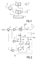
- a common antenna 1 is sufficient, which is optionally connected via an antenna switch 2 to a receiving part 3 or a transmitting part 4 of the radio.
- a control circuit 5 is provided for controlling the antenna switch 2 as well as the receiving part 3 and the transmitting part 4.
- the received signal 3 is processed so far that it is reproduced via a loudspeaker.
- Spoken signals are recorded by a microphone 7 and also processed in a known manner by the transmitting part 4.
- the transmitting part contains a low-frequency part for amplifying the microphone signal, a coding part for data reduction of the microphone signal, one or more oscillators for generating a carrier signal, a modulator by means of which the time-compressed speech signal is applied to the carrier signal, and a transmitting output stage which is used for power amplification and power control sending signal.
- a modulation signal U mod is a controllable HF driver amplifier 10 fed.
- the controllable HF driver amplifier 10 has a control input.
- the output amplitude of the controllable RF amplifier is set as a function of the control voltage applied to its control input.
- the output of the controllable HF driver amplifier 10 is connected to an HF power output stage 11 with constant power amplification. Via an RF output filter 12, the output signal of the RF output stage 11 is passed to an antenna 14 via a switch contact of an antenna switch 13.
- the antenna switch 13 is shown in Fig. 2 in the switching position of the transmission mode. In reception mode, the antenna switch 13 is in the other switching position, so that the antenna input signal is routed to the reception stage RX.
- the input signal of the RF power output stage 11 is also coupled out without attenuation via an isolating amplifier. Because of its function of deriving a value proportional to the RF power and at the same time providing sufficient power for the subsequent arrangement for RF rectification 16, this isolating amplifier is referred to below as sensor driver amplifier 15.
- the RF signal amplified by the sensor driver amplifier 15 is conducted from the coupling capacitor 20 to the cathode of an RF rectifier diode 161.
- a second capacitor 164 lies between the anode of the HF rectifier diode 161 and ground.
- the rectified HF signal is fed to a summing amplifier 32 via a first coupling resistor 21.
- the rectifier diode 161 is connected to a reference voltage U ref via an RF choke 163.
- the direct current flows via the rectifier diode 161 and a second resistor 22 to a first current source 30.
- the output voltage of the summing amplifier 32 is subtracted from the output voltage of the rectifier diode 161, so that only the rectified RF voltage remains as the output signal of the summing amplifier 32 .
- the same diode as the HF rectifier diode 161 is preferably selected as the compensation diode 162.
- the compensation diode 162 is also connected with its anode to the comparison voltage U ref .
- the cathode of the compensation diode 162 is connected via a third resistor 23 to the inverting input of the summing amplifier. Furthermore, the cathode of the compensation diode 162 is connected to a second constant current source 31 via a fourth resistor 24.
- a third resistor 23 to the inverting input of the summing amplifier.
- the cathode of the compensation diode 162 is connected to a second constant current source 31 via a fourth resistor 24.
- the resistance values of the first resistor 21 and third resistor 23 as well as of the second resistor 22 and fourth resistor 24 are chosen to be identical in pairs.
- the current sources 30 and 31 must of course also be selected so that they have the same constant currents.
- the output of the summing amplifier 32 is fed to the inverting input of a control amplifier 17.
- a control voltage U p is fed to the non-inverting input of the control amplifier 17.
- the difference between the two voltages results in the control voltage required to control the controllable RF preamplifier 10. In this way, the control loop is closed.
- Further elements of the control circuit known to the person skilled in the art, such as filters and offset compensation circuits, are not included in FIG. 2 for reasons of clarity.
- the desired output power is specified with the aid of the control voltage U p .
- the signal course of the edges can be specified here by the control circuit 5.
- the extensive decoupling of the output of the RF power output stage 11 from the output signal of the sensor driver amplifier 15 ensures that mismatches in the antenna have no effect on the control voltage U p of the driver amplifier 10. This ensures that the spectrum of the TDMA signal always remains of a constant quality regardless of the adaptation of the transmission output stage.
- the circuit according to the invention can be completely in a Monolithic Microwave Integrated Circuit (MMIC), for. B. on a gallium arsenide basis.
- MMIC Monolithic Microwave Integrated Circuit
- An important aspect for good control accuracy is that any change in the gain of the high-frequency output stage 11 is approximately compensated for by a change in the gain of the isolating amplifier 15.
- the output powers of the main amplifier and isolation amplifier are then well correlated with one another, so that the regulation of the output of the isolation amplifier leads to precise regulation of the main output.
- a close match between the main and isolation amplifiers can be achieved by both being implemented together on a common integrated circuit (e.g. silicon or gallium arsenide), thereby bringing about the technologies brought about by these technologies Possibilities of an excellent component match can be exploited.
Landscapes
- Engineering & Computer Science (AREA)
- Computer Networks & Wireless Communication (AREA)
- Signal Processing (AREA)
- Transmitters (AREA)
- Control Of Amplification And Gain Control (AREA)
Applications Claiming Priority (2)
| Application Number | Priority Date | Filing Date | Title |
|---|---|---|---|
| DE4339526 | 1993-11-19 | ||
| DE4339526A DE4339526A1 (de) | 1993-11-19 | 1993-11-19 | Funkgerät mit Sendeleistungsregelung |
Publications (3)
| Publication Number | Publication Date |
|---|---|
| EP0654900A2 true EP0654900A2 (fr) | 1995-05-24 |
| EP0654900A3 EP0654900A3 (fr) | 1996-01-31 |
| EP0654900B1 EP0654900B1 (fr) | 1999-02-10 |
Family
ID=6502989
Family Applications (1)
| Application Number | Title | Priority Date | Filing Date |
|---|---|---|---|
| EP94203303A Expired - Lifetime EP0654900B1 (fr) | 1993-11-19 | 1994-11-14 | Appareil de radiocommunication avec commande de puissance d'émission |
Country Status (7)
| Country | Link |
|---|---|
| US (1) | US5832374A (fr) |
| EP (1) | EP0654900B1 (fr) |
| JP (2) | JP4021502B2 (fr) |
| KR (1) | KR100368668B1 (fr) |
| CN (1) | CN1071959C (fr) |
| DE (2) | DE4339526A1 (fr) |
| SG (1) | SG50713A1 (fr) |
Cited By (3)
| Publication number | Priority date | Publication date | Assignee | Title |
|---|---|---|---|---|
| DE19613625C1 (de) * | 1996-04-04 | 1997-07-24 | Siemens Ag | Verstärkeranordnung mit regelbarer Ausgangsleistung zur Verstärkung eines hochfrequenten Eingangssignals |
| DE19603722A1 (de) * | 1996-02-02 | 1997-08-07 | Telefunken Microelectron | Integrierte HF-Eingangsstufe |
| EP1028525A3 (fr) * | 1999-02-11 | 2001-02-07 | DaimlerChrysler AG | Emetteur portable, notamment clef à télécommande radiofréquence |
Families Citing this family (12)
| Publication number | Priority date | Publication date | Assignee | Title |
|---|---|---|---|---|
| DE19705447B4 (de) * | 1997-02-13 | 2006-02-02 | Robert Bosch Gmbh | Funkgerät |
| US6853644B1 (en) * | 1999-12-22 | 2005-02-08 | Intel Corporation | Method and apparatus for driving data packets |
| US20030054780A1 (en) * | 2000-09-05 | 2003-03-20 | Hitachi, Ltd. | High frequency power amplifying circuit, and mobile communication apparatus using it |
| DE10132352A1 (de) * | 2001-07-04 | 2003-01-23 | Infineon Technologies Ag | Vorrichtung und Verfahren zur Konstanthaltung der Sendeleistung von Funkgeräten |
| US7010284B2 (en) * | 2002-11-06 | 2006-03-07 | Triquint Semiconductor, Inc. | Wireless communications device including power detector circuit coupled to sample signal at interior node of amplifier |
| US7187062B2 (en) * | 2004-04-14 | 2007-03-06 | Avago Technologies Wireless Ip (Singapore) Pte. Ltd. | Coupler detector |
| US8000737B2 (en) * | 2004-10-15 | 2011-08-16 | Sky Cross, Inc. | Methods and apparatuses for adaptively controlling antenna parameters to enhance efficiency and maintain antenna size compactness |
| US7663555B2 (en) * | 2004-10-15 | 2010-02-16 | Sky Cross Inc. | Method and apparatus for adaptively controlling antenna parameters to enhance efficiency and maintain antenna size compactness |
| US7834813B2 (en) * | 2004-10-15 | 2010-11-16 | Skycross, Inc. | Methods and apparatuses for adaptively controlling antenna parameters to enhance efficiency and maintain antenna size compactness |
| DE102012203026A1 (de) * | 2012-02-28 | 2013-08-29 | Sennheiser Electronic Gmbh & Co. Kg | Hochfrequenzsender |
| CN108205130B (zh) * | 2017-12-22 | 2021-11-30 | 重庆物奇科技有限公司 | 深度传感器、探测系统及传感器的发射功率的控制方法 |
| CN112427776B (zh) * | 2020-11-12 | 2022-09-27 | 镇江市金舟软件有限责任公司 | 一种船体焊接工时测量装置及方法 |
Family Cites Families (13)
| Publication number | Priority date | Publication date | Assignee | Title |
|---|---|---|---|---|
| JPS55120232A (en) * | 1979-03-08 | 1980-09-16 | Nec Corp | Repeater |
| US4602218A (en) * | 1985-04-30 | 1986-07-22 | Motorola, Inc. | Automatic output control circuitry for RF power amplifiers with wide dynamic range |
| US4737733A (en) * | 1986-10-29 | 1988-04-12 | Rca Corporation | Overdrive control of FET power amplifier |
| DE3742270C1 (en) * | 1987-12-12 | 1989-02-23 | Ant Nachrichtentech | Control stage for a radio-frequency power amplifier |
| KR930000434Y1 (ko) * | 1989-11-30 | 1993-01-30 | 현대전자산업 주식회사 | 출력 레벨 균등 회로 |
| DE3940295C2 (de) * | 1989-12-06 | 1997-10-02 | Philips Patentverwaltung | Mobilfunkgerät und Hochfrequenzsender mit geregelter Ausgangsleistung |
| US5126688A (en) * | 1990-03-20 | 1992-06-30 | Oki Electric Co., Ltd. | Power amplifying apparatus for wireless transmitter |
| JPH07118617B2 (ja) * | 1990-07-19 | 1995-12-18 | 沖電気工業株式会社 | 電力増幅装置及び送信装置 |
| TW198152B (fr) * | 1990-10-18 | 1993-01-11 | Hitachi Seisakusyo Kk | |
| KR930004093B1 (ko) * | 1990-11-30 | 1993-05-20 | 현대전자산업 주식회사 | 셀룰러 폰의 초기 억세스 확률 증대장치 및 방법 |
| GB9105064D0 (en) * | 1991-03-11 | 1991-04-24 | Philips Electronic Associated | Power amplifier and transmitting apparatus including such a power amplifier |
| DE69323794T2 (de) * | 1992-06-05 | 1999-09-09 | Japan Radio Co. Ltd. | Vorrichtung zur Sendeleistungssteuerung mit Vorspannungsstabilisierung |
| US5404586A (en) * | 1992-09-29 | 1995-04-04 | Fujitsu Ltd. | Transmitter having automatic power controller |
-
1993
- 1993-11-19 DE DE4339526A patent/DE4339526A1/de not_active Withdrawn
-
1994
- 1994-11-14 EP EP94203303A patent/EP0654900B1/fr not_active Expired - Lifetime
- 1994-11-14 SG SG1996009467A patent/SG50713A1/en unknown
- 1994-11-14 DE DE59407801T patent/DE59407801D1/de not_active Expired - Lifetime
- 1994-11-18 KR KR1019940030356A patent/KR100368668B1/ko not_active Expired - Lifetime
- 1994-11-19 CN CN94120066A patent/CN1071959C/zh not_active Expired - Lifetime
- 1994-11-21 JP JP28692794A patent/JP4021502B2/ja not_active Expired - Lifetime
-
1996
- 1996-11-01 US US08/742,330 patent/US5832374A/en not_active Expired - Lifetime
-
2007
- 2007-01-15 JP JP2007006143A patent/JP2007110763A/ja active Pending
Cited By (5)
| Publication number | Priority date | Publication date | Assignee | Title |
|---|---|---|---|---|
| DE19603722A1 (de) * | 1996-02-02 | 1997-08-07 | Telefunken Microelectron | Integrierte HF-Eingangsstufe |
| DE19603722B4 (de) * | 1996-02-02 | 2005-03-31 | Atmel Germany Gmbh | HF-Eingangsstufe |
| DE19613625C1 (de) * | 1996-04-04 | 1997-07-24 | Siemens Ag | Verstärkeranordnung mit regelbarer Ausgangsleistung zur Verstärkung eines hochfrequenten Eingangssignals |
| EP1028525A3 (fr) * | 1999-02-11 | 2001-02-07 | DaimlerChrysler AG | Emetteur portable, notamment clef à télécommande radiofréquence |
| US6754476B1 (en) | 1999-02-11 | 2004-06-22 | Daimlerchrysler Ag | Transportable radio transmitter, especially a remote |
Also Published As
| Publication number | Publication date |
|---|---|
| DE59407801D1 (de) | 1999-03-25 |
| JP2007110763A (ja) | 2007-04-26 |
| EP0654900A3 (fr) | 1996-01-31 |
| CN1111856A (zh) | 1995-11-15 |
| KR100368668B1 (ko) | 2003-05-17 |
| EP0654900B1 (fr) | 1999-02-10 |
| DE4339526A1 (de) | 1995-05-24 |
| KR950016031A (ko) | 1995-06-17 |
| JP4021502B2 (ja) | 2007-12-12 |
| JPH07202601A (ja) | 1995-08-04 |
| US5832374A (en) | 1998-11-03 |
| HK1019019A1 (en) | 2000-01-14 |
| CN1071959C (zh) | 2001-09-26 |
| SG50713A1 (en) | 1998-07-20 |
Similar Documents
| Publication | Publication Date | Title |
|---|---|---|
| DE69434350T2 (de) | Sender und Verfahren für einen Sender zur Kompensation von veränderlicher Last ohne Isolator | |
| DE4291720C2 (de) | Verfahren und Vorrichtung zur Detektion und Beseitigung einer Sättigung bei Leistungsverstärkern | |
| EP0654900B1 (fr) | Appareil de radiocommunication avec commande de puissance d'émission | |
| DE69522085T2 (de) | Leistungsregler für HF-Sender | |
| DE4291712C1 (de) | Vorrichtung zur Steuerung der Sendeleistung bei einem CDMA-Funkgerät | |
| DE69930780T2 (de) | Leistungsverstärker | |
| EP1211801B1 (fr) | Emetteur utilisant une boucle polaire | |
| DE69902289T2 (de) | Verfahren und gerät zum verhindern von leistungsverstärkersättigung | |
| DE112020003995T5 (de) | Einhüllendennachverfolgung auf mehreren niveaus mit analoger schnittstelle | |
| DE3231108A1 (de) | Sprachuebertragungseinrichtung mit leitungsgespeistem empfaenger-konditionierungsschaltkreis | |
| DE69229246T2 (de) | Im Auto montierter Verstärker für Einsteckverbindung mit einem Mobilfunktelefon | |
| DE102008052927B4 (de) | Senderanordnung | |
| DE69935901T2 (de) | Mobiles tragbares Endgerät und Sendeeinrichtung mit Leistungsregelung | |
| DE4409382C2 (de) | Sendeempfangsgerät | |
| EP1456992B1 (fr) | Ensemble emetteur permettant la transmission de donnees en continu | |
| DE60108944T2 (de) | Kanalselektiver Verstärker mit abstimmbarem Filter | |
| EP1168500A2 (fr) | Commutateur d'antenne pour un émetteur-récepteur mobile | |
| DE4342249C2 (de) | Antennenschalter und Verfahren zum Verbinden oder Entkoppeln eines Empfängerschaltkreises mit einer Antenne | |
| DE2709575A1 (de) | Hochfrequenz-sender-empfaenger | |
| DE2753130C3 (de) | Schaltung zum Empfang und zum Aussenden von Signalen | |
| DE69431218T2 (de) | Verfahren zur Bedienung eines Funktelefons | |
| DE102009029422B4 (de) | Sender mit Hybrid-Leistungsregelung | |
| DE10026152C2 (de) | Drahtloses Sendeempfangsgerät | |
| EP0602608A1 (fr) | Radio émetteur-récepteur mobile | |
| WO2004059834A1 (fr) | Circuit electronique servant a transmettre des informations |
Legal Events
| Date | Code | Title | Description |
|---|---|---|---|
| PUAI | Public reference made under article 153(3) epc to a published international application that has entered the european phase |
Free format text: ORIGINAL CODE: 0009012 |
|
| AK | Designated contracting states |
Kind code of ref document: A2 Designated state(s): DE FR GB IT |
|
| PUAL | Search report despatched |
Free format text: ORIGINAL CODE: 0009013 |
|
| AK | Designated contracting states |
Kind code of ref document: A3 Designated state(s): DE FR GB IT |
|
| 17P | Request for examination filed |
Effective date: 19960731 |
|
| 17Q | First examination report despatched |
Effective date: 19970102 |
|
| GRAG | Despatch of communication of intention to grant |
Free format text: ORIGINAL CODE: EPIDOS AGRA |
|
| GRAG | Despatch of communication of intention to grant |
Free format text: ORIGINAL CODE: EPIDOS AGRA |
|
| GRAH | Despatch of communication of intention to grant a patent |
Free format text: ORIGINAL CODE: EPIDOS IGRA |
|
| RAP3 | Party data changed (applicant data changed or rights of an application transferred) |
Owner name: KONINKLIJKE PHILIPS ELECTRONICS N.V. Owner name: PHILIPS PATENTVERWALTUNG GMBH |
|
| GRAH | Despatch of communication of intention to grant a patent |
Free format text: ORIGINAL CODE: EPIDOS IGRA |
|
| GRAA | (expected) grant |
Free format text: ORIGINAL CODE: 0009210 |
|
| AK | Designated contracting states |
Kind code of ref document: B1 Designated state(s): DE FR GB IT |
|
| REF | Corresponds to: |
Ref document number: 59407801 Country of ref document: DE Date of ref document: 19990325 |
|
| GBT | Gb: translation of ep patent filed (gb section 77(6)(a)/1977) |
Effective date: 19990305 |
|
| ITF | It: translation for a ep patent filed | ||
| ET | Fr: translation filed | ||
| PLBE | No opposition filed within time limit |
Free format text: ORIGINAL CODE: 0009261 |
|
| STAA | Information on the status of an ep patent application or granted ep patent |
Free format text: STATUS: NO OPPOSITION FILED WITHIN TIME LIMIT |
|
| RAP4 | Party data changed (patent owner data changed or rights of a patent transferred) |
Owner name: KONINKLIJKE PHILIPS ELECTRONICS N.V. Owner name: PHILIPS CORPORATE INTELLECTUAL PROPERTY GMBH |
|
| 26N | No opposition filed | ||
| REG | Reference to a national code |
Ref country code: GB Ref legal event code: IF02 |
|
| REG | Reference to a national code |
Ref country code: GB Ref legal event code: 732E |
|
| REG | Reference to a national code |
Ref country code: FR Ref legal event code: TP |
|
| PGFP | Annual fee paid to national office [announced via postgrant information from national office to epo] |
Ref country code: IT Payment date: 20101106 Year of fee payment: 17 |
|
| PGFP | Annual fee paid to national office [announced via postgrant information from national office to epo] |
Ref country code: FR Payment date: 20111205 Year of fee payment: 18 |
|
| REG | Reference to a national code |
Ref country code: FR Ref legal event code: ST Effective date: 20130731 |
|
| PG25 | Lapsed in a contracting state [announced via postgrant information from national office to epo] |
Ref country code: IT Free format text: LAPSE BECAUSE OF NON-PAYMENT OF DUE FEES Effective date: 20121114 |
|
| PG25 | Lapsed in a contracting state [announced via postgrant information from national office to epo] |
Ref country code: FR Free format text: LAPSE BECAUSE OF NON-PAYMENT OF DUE FEES Effective date: 20121130 |
|
| PGFP | Annual fee paid to national office [announced via postgrant information from national office to epo] |
Ref country code: GB Payment date: 20131025 Year of fee payment: 20 Ref country code: DE Payment date: 20131022 Year of fee payment: 20 |
|
| REG | Reference to a national code |
Ref country code: DE Ref legal event code: R071 Ref document number: 59407801 Country of ref document: DE |
|
| REG | Reference to a national code |
Ref country code: DE Ref legal event code: R071 Ref document number: 59407801 Country of ref document: DE |
|
| REG | Reference to a national code |
Ref country code: GB Ref legal event code: PE20 Expiry date: 20141113 |
|
| PG25 | Lapsed in a contracting state [announced via postgrant information from national office to epo] |
Ref country code: GB Free format text: LAPSE BECAUSE OF EXPIRATION OF PROTECTION Effective date: 20141113 |