EP0654940B1 - Verfahren und Gerät zur Vektorfehlerdiffusion mit Ausgabefarbsteuerung - Google Patents
Verfahren und Gerät zur Vektorfehlerdiffusion mit Ausgabefarbsteuerung Download PDFInfo
- Publication number
- EP0654940B1 EP0654940B1 EP94308059A EP94308059A EP0654940B1 EP 0654940 B1 EP0654940 B1 EP 0654940B1 EP 94308059 A EP94308059 A EP 94308059A EP 94308059 A EP94308059 A EP 94308059A EP 0654940 B1 EP0654940 B1 EP 0654940B1
- Authority
- EP
- European Patent Office
- Prior art keywords
- color
- pixel
- ink
- blue
- red
- Prior art date
- Legal status (The legal status is an assumption and is not a legal conclusion. Google has not performed a legal analysis and makes no representation as to the accuracy of the status listed.)
- Expired - Lifetime
Links
Images

Classifications
-
- H—ELECTRICITY
- H04—ELECTRIC COMMUNICATION TECHNIQUE
- H04N—PICTORIAL COMMUNICATION, e.g. TELEVISION
- H04N1/00—Scanning, transmission or reproduction of documents or the like, e.g. facsimile transmission; Details thereof
- H04N1/40—Picture signal circuits
-
- H—ELECTRICITY
- H04—ELECTRIC COMMUNICATION TECHNIQUE
- H04N—PICTORIAL COMMUNICATION, e.g. TELEVISION
- H04N1/00—Scanning, transmission or reproduction of documents or the like, e.g. facsimile transmission; Details thereof
- H04N1/46—Colour picture communication systems
- H04N1/52—Circuits or arrangements for halftone screening
Definitions
- the invention relates to an apparatus and a method for controlling colors printed by a printer or displayed on a monitor to reduce the visibility of error diffusion dot patterns, and more particularly, to an apparatus and method for performing vector error diffusion with output color control.
- Digital halftoning is the process of converting a continuous tone image to bi-level.
- Many output devices including many printers and some CRT (cathode ray tube) and LCD (liquid crystal display) based devices are intrinsically bi-level, that is, the process can only print or display a dot or no dot.
- CTR cathode ray tube
- LCD liquid crystal display
- a variety of geometrical patterns are created such that a group of dots and blank areas represent the continuous tone image as closely as possible.
- the halftoned image is only an approximate representation of the continuous tone image, there are differences between the continuous tone image and the halftone image. Those areas of the halftone pattern that do not match the original image are noise or error.
- An objective of much research in digital halftoning is reducing the amount of visible noise.
- Digital halftoning can be classified into two classes: "conventional, passive halftoning” and “active halftoning,” with error diffusion being a widespread method of choice in the latter category.
- Conventional passive halftoning (discussed first) yields an appearance that is similar to that provided by classical analogue processes developed before digital techniques were available; it is most appropriate for devices that cannot display isolated pixels.
- Error diffusion produces an image appearance more like that created by the pointillist painters at around the end of the 19th century. It is most appropriate for devices that can display isolated pixels. Error diffusion tends to have noise at higher, and hence less visible spatial frequencies, often resulting in a more pleasing appearance, see for instance: “Threshold Modulation in Error Diffusion," by K. T. Knox and R. Eschbach, Journal of Electronic Imaging 3, pp. 185-192(1993) and the references cited therein.
- US-A-4,625,222 to Bassettit et al. discloses a print enhancement control system for an electrostatic copier wherein control logic circuitry processes a set of image altering parameters to improve image production quality. These parameters have fixed or predetermined values and improve image quality by modifying modulated gray scale signals.
- US-A-4,700,229 to Hermann et al. discloses an image enhancement circuit which converts a low quality image signal into a high quality image signal by modifying the binary representation of a picture.
- Image enhancement is accomplished by multiplying a series of error difference signals by a series of weighting factors which produce clearer images by improving apparent picture resolution.
- US-A-4,672,463 to Tomohisa et al. discloses a method of improving image quality within an electrostatic reproduction machine wherein the sharpness of an image is improved based on the value of an image sharpness control parameter that has been calculated by examining the copy quality of an original.
- US-A-4,709,250 to Takeuchi discloses an image forming apparatus which improves the halftone image quality of an original.
- the pulse width of a reference control signal controls and improves image quality in response to detected image density signals.
- US-A-4,724,461 to Rushing discloses an image improving process control for an electrostatic copying machine which maintains high image quality by adjusting a set of process control parameters.
- US-A-4,256,401 to Fujimura et al. discloses an image density adjustment method wherein a predetermined image density level within an electrostatic copying machine is maintained at the standard density by a varying set of input control parameters.
- error diffusion As mentioned above, another way of converting from continuous tone to a bi-level representation is error diffusion as disclosed in an article entitled "An Adaptive Algorithm for Spatial Greyscale" by Robert W. Floyd and Louis Steinberg, Proc. Soc. Inf. Disp. 17, 75-77 (1976).
- the process of error diffusion involves an algorithm which determines whether or not to print a dot at a certain location based on a comparison of the continuous tone data with a threshold value. Gray levels above a chosen threshold are assigned a dot to be printed and those below the threshold are not assigned a dot to be printed. If the threshold corresponds to midway between black and white, the method always chooses the closer of black and white.
- the fraction of the error added to each neighbour depends on a set of weights, the total error being multiplied by the weight corresponding to a given neighbour and then added to the value of that neighbour.
- the choice of weight can greatly affect the image quality, and much has been said about weights appropriate for giving pleasing results.
- Three examples of weights other than those in the original Floyd and Steinberg algorithm may be found in papers by Jarvis, Judice, and Ninkey ("A Survey of Techniques for Display of Continuous-Tone Pictures on Bilevel Displays", Computer Graphics and image Processing, 5, pp. 13-40, 1976), Stucki, ("Image Processing for Document Reproduction", Advances in Digital Image Processing, pp. 177-218, New York, Plenum, 1979), and Fan, ("A Simple Modification of Error Diffusion Weights", Proceedings of the IS&T 46th Annual Conference, pp. 113-114, Boston 1993).
- a variation of the Floyd and Steinberg error diffusion algorithm involves using a varying threshold to determine whether to print or display a dot.
- varying threshold algorithms are: C. Billotet-Hoffmann and O. Bryngdahl, "On the Error Diffusion Technique for Electronic Halftoning", Proc. Soc. Inf. Disp. 24, pp. 253-258 (1983), in which a dither pattern was used as a threshold; US-A-5,045,952 to Eschbach in which a function of the input signal was used as the threshold; and US-A-5,055,942 to Levien in which a function of the binary output was used as the threshold.
- vector error diffusion is described in a paper by Dennis Venable, Judy Stinehour and Paul Roetling ("Selection and Use of Small Color Sets for Pictorial Display", Proc IS&T Annual Meeting, Rochester 1990) and in a paper by R. Miller and J. Sullivan ("Color Halftoning Using Error Diffusion and a Human Visual System Model", Proc IS&T Annual Meeting, Rochester 1990).
- colors are treated as points in a three dimensional space, with the colors printable or displayable at given pixel discrete locations within that space. When a continuous tone color is to be displayed, the closest displayable color is selected, and the error is calculated as a vector in color space.
- the "closeness” might be the simple distance in color space or a weighted distance based on the human visual model.
- the vector is the difference between the desired color and the available color.
- the (vector) error is then diffused in the same way as in normal error diffusion.
- the invention also provides an apparatus for determining colors of a plurality of pixels based on an original image in accordance with claim 10.
- the method and apparatus of the invention influence dot pattern correlations using a modified vector error diffusion algorithm.
- the colour is selected partly on the basis of a distorted multi-dimensional colour space and also on the basis of the determined ink contribution.
- Improved color output is provided by taking into account effects of interactions between dot patterns of different color components comprising a color image.
- the method and apparatus of the invention reduce the visibility of error diffusion dot patterns by reducing luminance variation and increasing pattern frequency.
- Improving color output is also provided taking into account effects of toner coverage and ink coverage for an individual color pixel.
- the invention thus provides a method and apparatus for influencing dot pattern correlations using vector error diffusion.
- the most common and simple ways to perform error diffusion of color images are to treat each color component individually or treat each color as a quantity in a 3-dimensional space and apply a vector error diffusion to that quantity.
- the invention modifies these approaches by treating all of the colors together and modifying the color output by taking into account the effects caused by interactions of dot patterns for each of the colors in the color image.
- the invention recognizes the inherent interactions between each color component of each pixel of a color image and the inherent properties of the human visual system.
- the invention uses these known interactions and properties and modifies known error diffusion techniques to reduce output image graininess without the need to include an explicit model of the human visual system.
- the invention modifies the process for deciding whether to turn on a pixel and modifying the process for deciding which color pixel to output.
- the invention seeks to print or display single pixels with good inter-separation registration while 1) minimizing the number of black and white pixels output; 2) minimizing the number of secondary colors printed if no black and white pixels are printed; and 3) dispersing the pixels printed or displayed to increase the dominant spatial frequency.
- By increasing the spatial frequency there is less visible noise produced; by avoiding black and secondary colors, there is less contrast between pixels that are printed and those that are not. Because visibility of noise is less at high frequencies and low contrast levels, the visibility of noise or graininess is substantially reduced.
- the invention provides a modified vector error diffusion algorithm that takes into account the effects of interactions of the dot patterns for the different color components in a color continuous tone image to be printed by a printer or displayed by a color display monitor.
- the apparatus and method reduce the luminance variation and increase the pattern frequency by influencing the number of separations used in local regions of the output image.
- the invention recognizes that when a white space is located next to a black pixel, there is a large contrast between white and black. Thus, a high contrast transition is introduced which is often perceived as disturbing noise. Further, there are also other combinations of colors that, when located adjacent to each other, contribute to high contrast and high noise.
- the method and apparatus of the invention lowers the visibility of this contrast by substituting colors having lower contrast and printing or displaying these colors next to each other. For example, instead of having black dots that are turned on or printed infrequently, cyan, magenta and yellow dots are turned on or printed frequently. This decreases the contrast and increases the spatial frequency. Thus, the noise pattern is far less visible.
- Cyan-Red-White combination of three pixels is required.
- a Cyan pixel is printed first.
- a Red pixel which is produced with a Magenta pixel printed on top of a Yellow pixel, are printed.
- a pixel is left blank.
- the invention diffuses this combination and prints a Cyan pixel, a Magenta pixel, and a Yellow pixel combination. This decreases the contrast and spreads out the error diffusion.
- a smoother gray image results with no overlapping pixels.
- a conventional color cube 10 is shown.
- the colors in the cube are: white 12; magenta 14; red 16; yellow 18 (back-left color block is hidden); green 20; cyan 22; blue 24; and black 26.
- the three inks used are generally cyan/magenta/yellow.
- Some printers use a fourth ink, black, in order to conserve the amount of ink printed.
- Color monitors use red, green and blue phosphors.
- a cross section of the color cube 10 shows four states consisting of white 12, magenta 14, cyan 22 and blue 24.
- the boundaries inside the cross section outline the regions for which all colors contained within such regions are closer to the corresponding corners of the cube than to any other corner. For example, if the input color is a light blue with a luminance range of 51-100%, the printer will print a white pixel (the color begins in the quadrant marked "white") and then will oscillate between white and blue in the appropriate amount (after errors are diffused, the colors will alternately fall into the blue quadrant 24 and the white quadrant 12).
- the input color is a dark blue with a luminance range of 0%-49%
- a blue pixel will be printed first followed by the oscillation of white and blue pixels in the appropriate combination.
- the oscillation between white and blue causes a large variation in luminance and, for the case of an ink jet printer representing "blue” as a combination of "cyan” and “magenta”, also in the ink coverage.
- the invention uses a distorted color cube, a possible cross section of which is shown in Figure 3. Again, the boundaries shown divide regions considered closer to the corresponding color.
- the distance measure used to find the closest vertex in the cube is distorted to take into account the interactions between the colors.
- Use of this distorted color cube reduces the noise and increases the spatial frequency by favouring the selection of primary colors over secondaries, white and black. This is done by arranging that colors not favoured are further away from most colors in the cube than are favoured colors . This can be acheived by changing thresholds used to select the closest color or by changing the method used to compute a distance.
- the conventional method would alternate between white (no color printed) and blue pixels.
- the first pixel is represented by cyan (assuming cyan is preferred over magenta).
- the succeeding pixels are printed using a preferred alternation between cyan and magenta. Because the region of colors considered closest to blue is smaller than the regions of colors considered closest to cyan or magenta, a large range of light blues can be printed using cyan and magenta, with some white pixels interspersed. This is advantageous because of the reduction in contrast between these colors against each other and against white, compared to the contrast between white and blue.
- One preferred embodiment measures the distance between the position in the color cube of the color required and the vertices of each of the colors in the color cube 10. The smallest distance is used as the color to print. With the distorted color cube, the coordinates of the vertices can be changed to prevent selecting undesirable colors such as black, white, red, green and blue.
- One method to represent the distorted color cube is to modify the distances according to several penalties.
- the penalty assigned to the distance for each color can be determined as a function of the ink coverage and/or a function of the luminance of the output state.
- the output pixel color is then selected by picking the smallest (modified) distance for all of the colors.
- These predetermined penalties can be stored in a look-up table.
- the closest color can be stored in a look-up table.
- a black pixel requires all three colors to be printed in the same pixel space. Therefore, black has a high penalty because it is less desirable due to the increase in ink consumption.
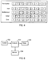
- FIG. 4 illustrates 1 dimensional error diffusion.
- Two dimensional error diffusion behaves in much the same way but is more difficult to illustrate.
- each pixel 1-9 has an output value of 3.
- a pixel is printed.
- the pixel printed has a value of ten.
- the error is then calculated and diffused to the next pixel (assume all of the error is diffused to the same neighbour). For example, pixel one has an input value of three. Assuming that there is no diffused error from the preceding pixel, the modified input is also three.
- the modified input is less than the threshold value, therefore no pixel is printed and the output is zero.
- the diffused error is now three.
- the modified input of pixel two is calculated by adding the input value of three and the error diffused from the previous pixel. Therefore, the modified input is six which exceeds the threshold value. A pixel is printed which forces the output to ten. The error is the modified input value minus the output value, therefore the error diffused is negative four. The modified input of pixel three is negative one. Therefore, the output is zero because the modified input does not exceed the threshold value. The error diffused is negative one and is diffused to pixel 4. After the process is completed, only pixels two, five and nine are printed.
- the total amount of ink of the set of colors for each dot is computed instead of merely performing color conversion. Then, every time the total amount of ink required exceeds a predetermined threshold, it is determined that a pixel is to be printed. Standard (non-vector) error diffusion is used to compute the total amount of ink required. Thus at each pixel, the total amount is thresholded, a pixel may or may not be printed, and the error in the total amount of ink is diffused to neighbouring pixels' total ink requirements.
- pixel(n) ON, if cyan + magenta + yellow > threshold, where ON does not specify the pixel color, but only the presence of a pixel and the pixel color is determined by using the distorted color cube described above.
- the invention determines when to turn on a pixel and what color that pixel should be to best reduce the luminance and decrease the visibility of the error pattern.
- step 100 the line counter (scancount) is set to zero and the pixel counter is set to zero.
- step 102 the pixel counter is checked to see whether all pixels have been printed. If all of the pixels in the scanline are printed, then step 126 is executed. The scancount is incremented by one. In step 128, the scancount is checked to see if all lines of the image page has been printed. If the image is completed, then the flow terminates. If the image is not complete, then the pixel counter is set to zero in step 130. Flow returns to step 102.
- An alternative to equation (1) is to compute the ink contribution of cyan, magenta and yellow. Assign cyan as 1-red, magenta as 1-green, and yellow as 1-blue, and then add magenta, cyan, and yellow to give the ink contribution.
- step 106 the contribution from the ink error diffusion buffer is added to the computed ink contribution of step 104.
- the error diffusion method was previously described with reference to Figure 4. The advantage of this method is that by taking the sum of the Cyan, Yellow and Magenta to determine the total amount of ink required for a particular dot, the total amount of ink of the set of colors for each dot is computed instead of merely performing color conversion. If a pixel has been set to a color and printed, the modified input value for that color (input plus error) will drop, making it unlikely for a second pixel of the color to be printed.
- step 108 A decision is made in step 108 to determine if the ink contribution is greater than one. If the ink contribution is zero or one, then no color (white) will be printed. In step 110, the color error is determined when no color was selected. The diffused color error is then diffused to neighboring pixels in step 120. Step 122 diffuses the ink contribution to neighboring pixels. The pixel counter is incremented by one in step 124, and flow returns to step 102.
- step 112 finds the closest color in a distorted color space.
- D cyan ⁇ (red,green,blue)-(-P cyan , 1+P cyan , 1+P cyan ) ⁇
- D magenta ⁇ (red,green,blue)-(1+P mag , -P mag , 1+P mag ) ⁇
- D yellow ⁇ (red,green,blue)-(1+P yel , 1+P yel , -P yel ) ⁇
- D black ⁇ (red,green,blue)-(-P blk , -P blk , -P blk ) ⁇
- D red ⁇ (red,green,blue)-(1+P red , -P red , -
- the minimum distance is determined: min(D cyan ,D magenta ,D yellow ,D black ,D red ,D green ,D blue ,D white ) The closest color of the distorted color space has the minimum distance to that color.
- step 114 the ink amount is subtracted from the ink contribution.
- the pixels are set in the output bitmaps. If the closest color is either, cyan, magenta or yellow, then set the corresponding pixel with an ink amount of one. If the closest color is black, then set the corresponding pixel with the ink amount of three. If the closest color is white, then set the ink amount to zero. If the closest color is either red, green or blue, then set two corresponding pixels and the ink amount is two.
- step 116 the color of pixels that are turned ON are sent to the output.
- the color error is determined by using the closest color in step 118. Similar to before, the output from step 118 is used to diffuse color error to neighboring pixels in step 120.
- step 122 the ink contribution error is diffused to neighboring pixels. The pixel count is incremented by one in step 124. Flow returns to step 102.
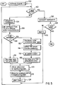
- a scanner 202 scans the original image.
- the original image is divided into sections, such as pixels, and each section is assigned a color from the continuous tone color image.
- the assigning of the colors is not limited to a scanner, but can be generated by any means.
- the assigned colors are sent to a computer 204, which uses the method of the invention to generate the pixel colors with a relatively low contrast and increased spatial frequency.
- the selected pixel colors are output to an output device such as a printer 206 or a monitor 208.
- the distance measures used in the distortion of the color cube can be implemented in different ways.
- One such alternative implementation is to vary the threshold, i.e., the dividing line between different colors, in accordance with the desired attributes of the color space.
Landscapes
- Engineering & Computer Science (AREA)
- Multimedia (AREA)
- Signal Processing (AREA)
- Facsimile Image Signal Circuits (AREA)
- Color Image Communication Systems (AREA)
- Image Processing (AREA)
Claims (10)
- Verfahren zum Bestimmen einer Farbe eines Pixels von einem Originalbild, mit den Schritten;a) Bestimmen (104) eines Druckfarben-Beitrages des Pixels aufgrund von Eingabedaten, die von dem Originalbild abgeleitet sind und von einem Wert (106) von einem Druckfarbenfehler-Diffusionspuffer, wobei der Druckfarbenbeitrag die zum Drucken des Pixels notwendige Druckfarbenmenge darstellt,b) Bestimmen einer modifizierten Farbe des Pixels aufgrund der Farbe des Pixels Im Originalbild und eines diffundierten Farbfehlers,c) Vergleichen (108) des bestimmten Druckfarbenbeitrags mit einem vorgegebenen Wert, und falls das Ergebnis des Vergleichs eine vorgegebene Bedingung erfüllt, Auswählen (112) der Farbe des Pixels aus einem vezerrten mehrdimensionalen Farbraum mit Benutzung der modifizierten Farbe des Pixels, wobei Abstände von Farben in dem Farbraum zu Ecken eines Farbwürfels so sind, dass sie eine vorgegebene Farbe begünstigen;d) Ausführen (114, 122) eines Druckfarben-Fehlerdiffusions-Vertahrens gemäß der Differenz zwischen dem bestimmten Druckfarbenbeitrag des Pixels und einer zum Drucken eines Pixels der gewählten Farbe benötigten Druckfarbenmenge, um Werte in dem Druckfarben-Fehlerdiffusions-Puffer für benachbarte Pixel zu aktualisieren;e) Ausführen (118, 120) eines Farbfehlerdiffusions-Vorgangs gemäß der Differenz zwischen der gewählten Farbe des Pixels und der modifizierten Farbe des Pixels, um den diffundierten Farbfehler für benachbarte Pixel zu aktualisieren; undf) Festsetzen (116) der gewählten Farbe des Pixels in einem Ausgabe-Bitmap, das das Originalbild darstellt.
- Verfahren nach Anspruch 1, bei dem die zum Bestimmen des Druckfarbenbeitrags verwendeten Eingabedaten die folgende Gleichung verwenden:
- Verfahren nach Anspruch 1, bei dem die zum Bestimmen des Druckfarbenbeitrags verwendeten Eingabedaten die folgende Gleichung verwenden:
- Verfahren nach Anspruch 1, bei dem der zum Aktualisieren des Druckfarben-Fehlerdiffusions-Puffers benutzt Wert und der diffundierte Farbfehler von einer für ein oder mehrere benachbarte Pixel ausgewählte Farbe abgeleitet werden.
- Verfahren nach Anspruch 4, bei dem der zum Aktualisieren des Druckfarben-Fehlerdiffusions-Puffers benutzte Wert auf einer Druckfarbenmenge begründet ist, die der von dem bestimmten Druckfarbenbeitrag subtrahierten (114) gewählten Farbe zugeordnet ist.
- Verfahren nach Anspruch 5, bei dem die der gewählten Farbe zugeordnete Druckfarbenmenge gleich einem der folgenden ist: null, falls die gewählte Farbe weiß ist; eins, falls die gewählte Farbe eine der Farben cyan, magenta und gelb ist und die Farbe das Festsetzen eines Pixels in einer Abtrennung erfordert; zwei, wenn die nächstliegende Farbe eine der Farben rot, grün oder blau ist, und die Farben das Festsetzen eines Pixels in zwei Separationen erfordert; und drei, wenn die nächstliegende Farbe schwarz ist.
- Verfahren nach Anspruch 5, bei dem die Druckfarbenmenge gleich einem der folgenden ist: null, falls die nächstliegende Farbe schwarz ist, eins, falls die nächstliegende Farbe eine der Farben rot, grün oder blau ist, und die Farbe das Festsetzen eines Pixels in einer Separation erfordert; zwei, falls die nächstliegende Farbe eine der Farben cyan, magenta oder gelb ist und die Farbe das Festsetzen eines Pixels in zwei Separationen erfordert; und drei, falls die nächstliegende Farbe weiß ist.
- Verfahren nach Anspruch 1, bei dem der Schritt des Auswählens der Farbe aufgrund des verzerrten Farbraums geschieht durch Bestimmen des kleinsten Abstands zwischen einer die Eingabedaten darstellenden Farbe und jeder der Druckfarben in dem verzerrten Raum durch Benutzen der folgenden Gleichungen:
- Verfahren nach Anspruch 1, bei dem der Schritte (108) des Wählens der Farbe des Pixels teilweise auf dem Vergleich des bestimmten Druckfarbenbeitrags mit einem vorgegebenen Wert begründet ist, so dass:wenn der bestimmte Druckfarbenbeitrag unter dem vorgegebenen Wert liegt, keine Farbe gewählt wird; undwenn der bestimmte Druckfarbenbeitrag über dem vorgegebenen Wert liegt, die im verzerrten Farbraum nächstliegende Farbe gewählt wird.
- Vorrichtung zum Bestimmen von Farben einer Vielzahl von auf einem Originalbild begründeten Pixeln, welche Vorrichtung umfasst:einen Abtaster (202) zum Abtasien des Originalbildes und Bilden von eine aktuelle Farbe darstellenden Eingabedaten;einen Computer (204) zum Bestimmen der Farbe der Vielzahl von Pixeln, welcher Computer enthält:einen Farbfehlerdiffusions-Puffer,einen Bestimmer zum Bestimmen (104) eines Druckfarbenbeitrags des Pixels aufgrund von dem Originalbild abgeleiteter Eingabedaten und eines Wertes (106) von dem Farbfehlerdiffusions-Puffer, wobei der Druckfarbenbeitreg die zum Drucken des Pixels notwendige Druckfarbenmenge darstellt, und zum Bestimmen einer modifizierten Farbe des Pixels aufgrund der Pixelfarbe in dem Originalbild und eines diffundierten Farbfehlers;einen Komparator zum Vergleichen (108) des bestimmten Druckfarbenbeitrags mit einem vorgegebenen Wert,einen Wähler, der, falls das Ergebnis des Vergleichs eine vorgegebene Bedingung erfüllt, die Farbe des Pixels aus einem verzerrten mehrdimensionalen Farbraum mit Benutzung der modifizierten Farbe des Pixels wählt, wobei Abstände von Farben innerhalb des Farbraums zu Ecken eines Farbwürfels so sind, dass sie eine vorgegebene Farbe begünstigen;einen Aktualisierer zum Ausführen (114, 122) eines Druckfarben-Fehlerdiffusionsvorgangs gemäß der Differenz zwischen dem bestimmten Druckfarbenbeitrag des Pixels und einer Druckfarbenmenge, die zum Drucken eines Pixels der gewählten Farbe benötigt wird, um Werte in dem Druckfarben-Fehlerdiffusions-Puffer für benachbarte Pixel zu aktualisieren und zum Ausführen (118, 120) eines Farbfehlerdiffusions-Vorgangs gemäß der Differenz zwischen der gewählten Pixelfarbe und der modifizierten Pixelfarbe zum Aktualisieren des diffundierten Farbfehlers für benachbarte Pixel;einen Ausleger zum Festsetzen der gewählten Farbe des Pixels in einem das Originalbild darstellende Ausgabe-Bitmap; undeinen Drucker (206) zum Formatieren der Ausgabe-Bitmap-Daten.
Applications Claiming Priority (2)
| Application Number | Priority Date | Filing Date | Title |
|---|---|---|---|
| US08/144,478 US5621546A (en) | 1993-11-02 | 1993-11-02 | Method and apparatus for vector error diffusion with output color control |
| US144478 | 1993-11-02 |
Publications (2)
| Publication Number | Publication Date |
|---|---|
| EP0654940A1 EP0654940A1 (de) | 1995-05-24 |
| EP0654940B1 true EP0654940B1 (de) | 2000-04-26 |
Family
ID=22508773
Family Applications (1)
| Application Number | Title | Priority Date | Filing Date |
|---|---|---|---|
| EP94308059A Expired - Lifetime EP0654940B1 (de) | 1993-11-02 | 1994-11-02 | Verfahren und Gerät zur Vektorfehlerdiffusion mit Ausgabefarbsteuerung |
Country Status (4)
| Country | Link |
|---|---|
| US (1) | US5621546A (de) |
| EP (1) | EP0654940B1 (de) |
| JP (1) | JP3621443B2 (de) |
| DE (1) | DE69424126T2 (de) |
Families Citing this family (58)
| Publication number | Priority date | Publication date | Assignee | Title |
|---|---|---|---|---|
| US5737453A (en) * | 1996-05-17 | 1998-04-07 | Canon Information Systems, Inc. | Enhanced error-diffusion method for color or black-and-white reproduction |
| US5784496A (en) * | 1996-09-26 | 1998-07-21 | Xerox Corporation | Error sum method and apparatus for intercolor separation control in a printing system |
| US5748785A (en) * | 1996-09-26 | 1998-05-05 | Xerox Corporation | Inter-separation color image processing using error diffusion |
| US6072591A (en) * | 1997-06-30 | 2000-06-06 | Xerox Corporation | Sum and difference error diffusion |
| US5991438A (en) * | 1997-07-31 | 1999-11-23 | Hewlett-Packard Company | Color halftone error-diffusion with local brightness variation reduction |
| US5982992A (en) * | 1997-09-05 | 1999-11-09 | Xerox Corporation | Error diffusion in color printing where an intra-gamut colorant is available |
| US6014233A (en) * | 1998-06-09 | 2000-01-11 | Xerox Corporation | Error diffusion for color images with semi-vector quantization |
| US6483606B1 (en) | 1998-08-26 | 2002-11-19 | Xerox Corporation | Error diffusion on moderate numbers of output colors |
| US6161919A (en) * | 1999-02-22 | 2000-12-19 | Xerox Corporation | Ink coverage reduction method for printers capable of printing multiple drop sizes |
| US6751358B1 (en) * | 1999-06-21 | 2004-06-15 | Xerox Corporation | Error diffusion for digital printing |
| US6717700B1 (en) | 1999-07-01 | 2004-04-06 | Xerox Corporation | Method and system for adjusting binary images |
| US6891641B1 (en) | 1999-08-27 | 2005-05-10 | Minolta Co., Ltd. | Method and apparatus for converting number of colors and processing image data |
| AU8025300A (en) * | 1999-10-15 | 2001-04-30 | Cv Us, Inc. | Halftoning method and system for improved color printing |
| US6671071B1 (en) * | 1999-10-19 | 2003-12-30 | Xerox Corporation | Threshold bias circuits for enhanced color error diffusion |
| US6535635B1 (en) | 1999-10-25 | 2003-03-18 | Xerox Corporation | Error clipping for vector error diffusion |
| US6608700B1 (en) | 1999-11-24 | 2003-08-19 | Xerox Corporation | Removal of error diffusion artifacts with alternating distribution weights |
| US6721063B1 (en) * | 2000-01-19 | 2004-04-13 | Xerox Corporation | Image rendering system and method using sum and difference error diffusion with arbitrary and redundant colors |
| US6760127B1 (en) | 2000-06-01 | 2004-07-06 | Xerox Corporation | Multi-level semi-vector error diffusion |
| US7099046B2 (en) | 2000-11-30 | 2006-08-29 | Canon Kabushiki Kaisha | Image processing apparatus and image processing method |
| US6751362B2 (en) * | 2001-01-11 | 2004-06-15 | Micron Technology, Inc. | Pixel resampling system and method for text |
| US7593135B2 (en) * | 2001-06-29 | 2009-09-22 | Eastman Kodak Company | Digital image multitoning method |
| JP3870056B2 (ja) * | 2001-10-04 | 2007-01-17 | キヤノン株式会社 | 画像処理装置及び方法及びコンピュータプログラム及びコンピュータ可読記憶媒体 |
| JP2003116015A (ja) * | 2001-10-04 | 2003-04-18 | Canon Inc | 画像処理装置及び方法及びコンピュータプログラム及びコンピュータ可読記憶媒体 |
| US20030179410A1 (en) * | 2002-03-21 | 2003-09-25 | Velde Koen Van De | Multilevel colour error-diffusion providing reduced sensitivity to printing process variability errors |
| JP3943981B2 (ja) * | 2002-04-10 | 2007-07-11 | キヤノン株式会社 | 画像処理装置及び方法 |
| JP2004015086A (ja) * | 2002-06-03 | 2004-01-15 | Canon Inc | 画像処理装置及びその制御方法 |
| US20040090654A1 (en) * | 2002-09-17 | 2004-05-13 | Luc Minnebo | FM screening with sub-dot phase modulation |
| US7551323B2 (en) * | 2003-04-16 | 2009-06-23 | Lexmark International, Inc. | Systems and methods for error diffusion |
| JP4065532B2 (ja) * | 2003-05-09 | 2008-03-26 | キヤノン株式会社 | 画像処理装置、画像処理方法およびプログラム |
| ES2681886T3 (es) * | 2003-08-14 | 2018-09-17 | Sicpa Holding Sa | Tramado dependiente del tono con tablas de consulta optimizadas |
| FR2865090B1 (fr) * | 2004-01-09 | 2007-06-15 | Sagem | Procede et dispositif d'etablissement de trames par diffusion d'erreur et limitation d'encre par matrices de valeurs de seuils |
| US7417772B2 (en) * | 2004-01-23 | 2008-08-26 | Sharp Laboratories Of America, Inc. | Vector error diffusion |
| US7352489B2 (en) * | 2004-03-24 | 2008-04-01 | Sharp Laboratories Of America, Inc. | Color error diffusion method for multi-level output device |
| US6977663B2 (en) * | 2004-03-29 | 2005-12-20 | Sharp Laboratories Of America, Inc. | Color error diffusion with color bleed control |
| RU2259602C1 (ru) * | 2004-04-05 | 2005-08-27 | Петрачков Дмитрий Евгеньевич | Способ формирования цвета пикселя |
| JP4420447B2 (ja) * | 2004-06-14 | 2010-02-24 | キヤノン株式会社 | 色処理装置および色処理方法 |
| US7091987B2 (en) * | 2004-08-02 | 2006-08-15 | Sharp Laboratories Of America, Inc. | Patterning and dot gain improvement for vector error diffusion |
| US7369274B2 (en) * | 2004-09-08 | 2008-05-06 | Sharp Laboratories Of America, Inc. | Color error diffusion method |
| US7570403B2 (en) * | 2005-03-16 | 2009-08-04 | Kabushiki Kaisha Toshiba | Color image processing apparatus |
| US20070019217A1 (en) * | 2005-07-24 | 2007-01-25 | Sharp Laboratories Of America, Inc. | Color calibration method and structure for vector error diffusion |
| US8285595B2 (en) * | 2006-03-29 | 2012-10-09 | Napo Enterprises, Llc | System and method for refining media recommendations |
| US9003056B2 (en) | 2006-07-11 | 2015-04-07 | Napo Enterprises, Llc | Maintaining a minimum level of real time media recommendations in the absence of online friends |
| US7719718B2 (en) * | 2007-03-13 | 2010-05-18 | Xerox Corporation | Threshold modification for limit cycle removal in vector error diffusion |
| US8316015B2 (en) | 2007-12-21 | 2012-11-20 | Lemi Technology, Llc | Tunersphere |
| US7952764B2 (en) * | 2008-02-05 | 2011-05-31 | Xerox Corporation | Hierarchical color error diffusion in a CMYKRGB domain |
| US7978371B2 (en) * | 2008-02-05 | 2011-07-12 | Xerox Corporation | Vector half-toning with minimum luminance variation dot formation |
| US8725740B2 (en) * | 2008-03-24 | 2014-05-13 | Napo Enterprises, Llc | Active playlist having dynamic media item groups |
| US8484311B2 (en) | 2008-04-17 | 2013-07-09 | Eloy Technology, Llc | Pruning an aggregate media collection |
| US8179568B2 (en) * | 2008-07-24 | 2012-05-15 | Xerox Corporation | Minimizing dot graininess in dot-on-dot printing devices |
| US20100070537A1 (en) * | 2008-09-17 | 2010-03-18 | Eloy Technology, Llc | System and method for managing a personalized universal catalog of media items |
| US8880599B2 (en) * | 2008-10-15 | 2014-11-04 | Eloy Technology, Llc | Collection digest for a media sharing system |
| US8484227B2 (en) | 2008-10-15 | 2013-07-09 | Eloy Technology, Llc | Caching and synching process for a media sharing system |
| US7916349B2 (en) * | 2008-10-27 | 2011-03-29 | Xerox Corporation | Color pixel error diffusion in a CMYK input color space |
| US20100157377A1 (en) * | 2008-12-18 | 2010-06-24 | Xerox Corporation | Uv fluorescence encoded background images using adaptive halftoning into disjoint sets |
| US8200602B2 (en) | 2009-02-02 | 2012-06-12 | Napo Enterprises, Llc | System and method for creating thematic listening experiences in a networked peer media recommendation environment |
| US8294964B2 (en) * | 2009-04-08 | 2012-10-23 | Xerox Corporation | CMYK to CMYKKpRGB transform for halftone dot overlap control |
| JP5237215B2 (ja) * | 2009-07-15 | 2013-07-17 | キヤノン株式会社 | 画像処理装置及び方法 |
| US8351084B2 (en) * | 2009-10-13 | 2013-01-08 | Xerox Corporation | Vector error diffusion with edge control |
Family Cites Families (14)
| Publication number | Priority date | Publication date | Assignee | Title |
|---|---|---|---|---|
| JPS5497432A (en) * | 1978-01-18 | 1979-08-01 | Ricoh Co Ltd | Image density control method |
| US4625222A (en) * | 1984-05-17 | 1986-11-25 | International Business Machines Corporation | Interacting print enhancement techniques |
| US4709250A (en) * | 1985-02-19 | 1987-11-24 | Canon Kabushiki Kaisha | Image forming apparatus |
| JPS61230571A (ja) * | 1985-04-05 | 1986-10-14 | Dainippon Screen Mfg Co Ltd | 画像走査装置 |
| NL8501956A (nl) * | 1985-07-09 | 1987-02-02 | Philips Nv | Beeldherstelschakeling. |
| US4693593A (en) * | 1986-06-24 | 1987-09-15 | Eastman Kodak Company | Electrographic process control |
| US4680645A (en) * | 1986-08-25 | 1987-07-14 | Hewlett-Packard Company | Method for rendering gray scale images with variable dot sizes |
| US4724461A (en) * | 1987-04-06 | 1988-02-09 | Eastman Kodak Company | Dynamic process control for electrostatographic machines |
| JPH01280969A (ja) * | 1988-05-06 | 1989-11-13 | Brother Ind Ltd | 画像処理装置 |
| US4930018A (en) * | 1988-12-02 | 1990-05-29 | Hewlett-Packard Company | Method and system for enhancing the quality of both color and black and white images produced by ink jet printers |
| US5045952A (en) * | 1989-08-21 | 1991-09-03 | Xerox Corporation | Method for edge enhanced error diffusion |
| US5070413A (en) * | 1989-10-10 | 1991-12-03 | Eastman Kodak Company | Color digital halftoning with vector error diffusion |
| US5055942A (en) * | 1990-02-06 | 1991-10-08 | Levien Raphael L | Photographic image reproduction device using digital halftoning to screen images allowing adjustable coarseness |
| JPH05336373A (ja) * | 1992-06-04 | 1993-12-17 | Toshiba Corp | 画像記録装置 |
-
1993
- 1993-11-02 US US08/144,478 patent/US5621546A/en not_active Expired - Lifetime
-
1994
- 1994-10-26 JP JP26291794A patent/JP3621443B2/ja not_active Expired - Fee Related
- 1994-11-02 DE DE69424126T patent/DE69424126T2/de not_active Expired - Lifetime
- 1994-11-02 EP EP94308059A patent/EP0654940B1/de not_active Expired - Lifetime
Also Published As
| Publication number | Publication date |
|---|---|
| US5621546A (en) | 1997-04-15 |
| EP0654940A1 (de) | 1995-05-24 |
| DE69424126T2 (de) | 2000-09-28 |
| JP3621443B2 (ja) | 2005-02-16 |
| DE69424126D1 (de) | 2000-05-31 |
| JPH07193726A (ja) | 1995-07-28 |
Similar Documents
| Publication | Publication Date | Title |
|---|---|---|
| EP0654940B1 (de) | Verfahren und Gerät zur Vektorfehlerdiffusion mit Ausgabefarbsteuerung | |
| US6178011B1 (en) | Adaptive image resolution enhancement technology | |
| US5325211A (en) | Error diffusion with output and input based feedback | |
| US5070413A (en) | Color digital halftoning with vector error diffusion | |
| EP0833499B1 (de) | Farbbildverarbeitung zwischen Auszügen mit Verwendung von Fehlerdiffusion | |
| US6870644B2 (en) | Tone dependent plane dependent error diffusion halftoning | |
| US6072591A (en) | Sum and difference error diffusion | |
| US5973803A (en) | Combined color halftoning | |
| US5463471A (en) | Method and system of color halftone reproduction | |
| EP0889639B1 (de) | Mehrpegelige Halbtonrasterung mit Rändern verringerter Textur und Deckungssteuerung | |
| Pappas | Model-based halftoning of color images | |
| US6014233A (en) | Error diffusion for color images with semi-vector quantization | |
| US6483606B1 (en) | Error diffusion on moderate numbers of output colors | |
| EP0817465B1 (de) | Fehlerdiffusionsverfahren mit symmetrischer Verbesserung | |
| US20020145758A1 (en) | Error diffusion with partial dots method and system | |
| EP0817466B1 (de) | Randverbesserte Fehlerdiffusion | |
| US20030128395A1 (en) | Color halftoning using a multi-level successive-filling halftone screening alogorithm | |
| US8363280B2 (en) | System and method of halftone printing of image spot colors using ranked ordered pairing of colorants and halftone screens | |
| US6844941B1 (en) | Color halftoning using a single successive-filling halftone screen | |
| US6760127B1 (en) | Multi-level semi-vector error diffusion | |
| US20070285695A1 (en) | Correlated secondary trc calibration method | |
| EP0772934B1 (de) | Bildwiedergabe unter benutzung von gleichmässig verteilten intensitätsgruppen | |
| US20040090654A1 (en) | FM screening with sub-dot phase modulation | |
| US20070081205A1 (en) | Image recording apparatus and method providing personalized color enhancement | |
| JP2004135317A (ja) | カラー画像処理装置およびカラー画像処理方法 |
Legal Events
| Date | Code | Title | Description |
|---|---|---|---|
| PUAI | Public reference made under article 153(3) epc to a published international application that has entered the european phase |
Free format text: ORIGINAL CODE: 0009012 |
|
| AK | Designated contracting states |
Kind code of ref document: A1 Designated state(s): DE FR GB |
|
| 17P | Request for examination filed |
Effective date: 19951124 |
|
| 17Q | First examination report despatched |
Effective date: 19980309 |
|
| GRAG | Despatch of communication of intention to grant |
Free format text: ORIGINAL CODE: EPIDOS AGRA |
|
| GRAG | Despatch of communication of intention to grant |
Free format text: ORIGINAL CODE: EPIDOS AGRA |
|
| GRAH | Despatch of communication of intention to grant a patent |
Free format text: ORIGINAL CODE: EPIDOS IGRA |
|
| GRAH | Despatch of communication of intention to grant a patent |
Free format text: ORIGINAL CODE: EPIDOS IGRA |
|
| GRAA | (expected) grant |
Free format text: ORIGINAL CODE: 0009210 |
|
| AK | Designated contracting states |
Kind code of ref document: B1 Designated state(s): DE FR GB |
|
| REF | Corresponds to: |
Ref document number: 69424126 Country of ref document: DE Date of ref document: 20000531 |
|
| ET | Fr: translation filed | ||
| PLBE | No opposition filed within time limit |
Free format text: ORIGINAL CODE: 0009261 |
|
| STAA | Information on the status of an ep patent application or granted ep patent |
Free format text: STATUS: NO OPPOSITION FILED WITHIN TIME LIMIT |
|
| 26N | No opposition filed | ||
| REG | Reference to a national code |
Ref country code: GB Ref legal event code: IF02 |
|
| PGFP | Annual fee paid to national office [announced via postgrant information from national office to epo] |
Ref country code: DE Payment date: 20131022 Year of fee payment: 20 Ref country code: GB Payment date: 20131025 Year of fee payment: 20 Ref country code: FR Payment date: 20131121 Year of fee payment: 20 |
|
| REG | Reference to a national code |
Ref country code: DE Ref legal event code: R071 Ref document number: 69424126 Country of ref document: DE |
|
| REG | Reference to a national code |
Ref country code: DE Ref legal event code: R071 Ref document number: 69424126 Country of ref document: DE |
|
| REG | Reference to a national code |
Ref country code: GB Ref legal event code: PE20 Expiry date: 20141101 |
|
| PG25 | Lapsed in a contracting state [announced via postgrant information from national office to epo] |
Ref country code: GB Free format text: LAPSE BECAUSE OF EXPIRATION OF PROTECTION Effective date: 20141101 |