EP0654952A2 - Procédé et dispositif pour l'affectation dynamique de canal pour communication "sans fil" - Google Patents
Procédé et dispositif pour l'affectation dynamique de canal pour communication "sans fil" Download PDFInfo
- Publication number
- EP0654952A2 EP0654952A2 EP94308473A EP94308473A EP0654952A2 EP 0654952 A2 EP0654952 A2 EP 0654952A2 EP 94308473 A EP94308473 A EP 94308473A EP 94308473 A EP94308473 A EP 94308473A EP 0654952 A2 EP0654952 A2 EP 0654952A2
- Authority
- EP
- European Patent Office
- Prior art keywords
- channel
- base station
- data
- processor
- base stations
- Prior art date
- Legal status (The legal status is an assumption and is not a legal conclusion. Google has not performed a legal analysis and makes no representation as to the accuracy of the status listed.)
- Granted
Links
Images




Classifications
-
- H—ELECTRICITY
- H04—ELECTRIC COMMUNICATION TECHNIQUE
- H04W—WIRELESS COMMUNICATION NETWORKS
- H04W16/00—Network planning, e.g. coverage or traffic planning tools; Network deployment, e.g. resource partitioning or cells structures
- H04W16/02—Resource partitioning among network components, e.g. reuse partitioning
- H04W16/10—Dynamic resource partitioning
-
- H—ELECTRICITY
- H04—ELECTRIC COMMUNICATION TECHNIQUE
- H04W—WIRELESS COMMUNICATION NETWORKS
- H04W16/00—Network planning, e.g. coverage or traffic planning tools; Network deployment, e.g. resource partitioning or cells structures
- H04W16/02—Resource partitioning among network components, e.g. reuse partitioning
- H04W16/12—Fixed resource partitioning
-
- H—ELECTRICITY
- H04—ELECTRIC COMMUNICATION TECHNIQUE
- H04W—WIRELESS COMMUNICATION NETWORKS
- H04W28/00—Network traffic management; Network resource management
- H04W28/16—Central resource management; Negotiation of resources or communication parameters, e.g. negotiating bandwidth or QoS [Quality of Service]
-
- H—ELECTRICITY
- H04—ELECTRIC COMMUNICATION TECHNIQUE
- H04W—WIRELESS COMMUNICATION NETWORKS
- H04W72/00—Local resource management
- H04W72/04—Wireless resource allocation
-
- H—ELECTRICITY
- H04—ELECTRIC COMMUNICATION TECHNIQUE
- H04W—WIRELESS COMMUNICATION NETWORKS
- H04W72/00—Local resource management
- H04W72/04—Wireless resource allocation
- H04W72/044—Wireless resource allocation based on the type of the allocated resource
- H04W72/0453—Resources in frequency domain, e.g. a carrier in FDMA
-
- H—ELECTRICITY
- H04—ELECTRIC COMMUNICATION TECHNIQUE
- H04W—WIRELESS COMMUNICATION NETWORKS
- H04W72/00—Local resource management
- H04W72/20—Control channels or signalling for resource management
- H04W72/21—Control channels or signalling for resource management in the uplink direction of a wireless link, i.e. towards the network
-
- H—ELECTRICITY
- H04—ELECTRIC COMMUNICATION TECHNIQUE
- H04W—WIRELESS COMMUNICATION NETWORKS
- H04W72/00—Local resource management
- H04W72/50—Allocation or scheduling criteria for wireless resources
- H04W72/54—Allocation or scheduling criteria for wireless resources based on quality criteria
- H04W72/541—Allocation or scheduling criteria for wireless resources based on quality criteria using the level of interference
-
- H—ELECTRICITY
- H04—ELECTRIC COMMUNICATION TECHNIQUE
- H04W—WIRELESS COMMUNICATION NETWORKS
- H04W88/00—Devices specially adapted for wireless communication networks, e.g. terminals, base stations or access point devices
- H04W88/08—Access point devices
-
- H—ELECTRICITY
- H04—ELECTRIC COMMUNICATION TECHNIQUE
- H04W—WIRELESS COMMUNICATION NETWORKS
- H04W92/00—Interfaces specially adapted for wireless communication networks
- H04W92/16—Interfaces between hierarchically similar devices
- H04W92/20—Interfaces between hierarchically similar devices between access points
Definitions
- the present invention relates to the field of wireless communication. More particularly it relates to the efficient use of the radio frequency spectrum by wireless communication devices.
- Wireless communication networks are typically comprised of a mobile switching center, base stations and mobile/portable units ("mobile units").
- the base stations are typically hardwired to the mobile switching center through communication lines such as optical communication lines.
- Each base station provides coverage for mobile units within a specified area called a "cell”.
- the base station for that cell assigns a frequency channel pair to the mobile unit.
- the frequency channel pair is comprised of an "uplink" frequency channel which is used for transmitting signals from the mobile unit to the base station, and a "downlink” frequency channel, which is used for receiving signals at the mobile unit from the base station.
- the frequency channel pair assigned to a particular mobile unit can be thought of as a single frequency channel and is often described as such by those skilled in the art.
- a mobile unit such as a cellular telephone, can communicate with other mobile units or hardwired units, through its communications with a base station.
- DCA Dynamic Channel Allocation
- Present DCA techniques can be grouped into two categories: traffic adaption and interference adaptation.
- Traffic adaption and interference adaptation.
- m-PPA m-Persistent Polite Aggressive
- a mobile unit measures the interference signal level on a channel pair and seizes that channel pair if the level indicates that no mobile units within a certain area, called a "neighborhood", are using that channel pair.
- a mobile unit after an unsuccessful attempt to find an unused channel pair, sends out a "seize” signal on a channel whose interference level indicates that only one other mobile unit in the seizing mobile unit's neighborhood is using the corresponding channel pair.
- the other mobile unit called the disturbed mobile unit, receives the "seize” signal and then looks for another channel pair.
- the "m-PPA” technique is similar to the “Aggressive” technique, however, if the disturbed mobile unit cannot find another available channel pair the seizing mobile unit releases the seized channel pair and searches for another channel pair.
- the mobile unit needs to be able to measure all channel pairs to determine which pair to make an attempt on. This may not be feasible. Furthermore the “Aggressive” technique can become unstable because when one mobile unit disturbs another it may start a series of changes in channel pair occupancy.
- MP DCA Traffic adaptation DCA
- channel pairs are assigned to or occupied by mobile units based on actual data concerning channel pair usage by mobile units. Traffic adaptation does not require the measuring of interference signal level but rather the reporting of data concerning actual channel pair usage.
- Maximum Packing DCA MP DCA
- MP DCA centralized information determines which frequency channel pairs are used by all mobile units in a network. Each time a mobile unit requests a frequency channel pair for communication, the best possible allocation scheme is determined and all channel pair allocations are updated.
- MP DCA requires centralized coordination and global information which is almost impossible to achieve in a network with a large number of channels and cells.
- One object of the present invention is to provide efficient use of frequency channels in wireless communication systems.
- a further object of the invention to provide a dynamic channel allocation technique which does not introduce significant delay in setting up calls or communications between base stations and mobile units.
- a further object of the invention is to provide a dynamic channel allocation technique which produces a minimum amount of interference.
- a further object of the invention is to provide an efficient traffic adaptation technique for channel allocation.
- channel pair occupancy and channel pair availability data at each base station for that base station and for its neighboring base stations.
- the neighboring base stations can be defined using, for example, a 1-cell or 2-cell buffering reuse constraint.
- the data is preferably provided in the form of an augmented channel pair occupancy (ACO) table.
- ACO augmented channel pair occupancy
- the channel pair occupancy and channel pair availability data is used to assign frequency channel pairs to requesting mobile units. Data in the table is changed based on channel pair occupancy and channel pair availability data received from neighboring base stations.
- dynamic channel allocation is accomplished by providing channel pair occupancy and channel pair availability data at a mobile switching center and using this data to assign channel pairs to requesting base stations and mobile units.
- data concerning channel pair occupancy by a base station and channel pairs available to a base station is transmitted from a base station to its neighboring base stations.
- channel pair occupancy and channel pair availability data is provided in the form of multiple tables located at a single mobile switching center and this data is used to assign channel pairs to base stations and mobile units.
- the same data is provided in a combined table located at a single mobile switching center and this data is used to assign channel pairs to base stations and mobile units.
- Fig. 1 illustrates a simplified wireless communication network 10 comprising a mobile switching center 12, a plurality of base stations, including base stations 20, 22, and 24, frequency channel pairs 30, 32, 34, 36, 38, and 40, and mobile units 60, 62, 64, 66, 68, and 70.
- Base station 20 is shown communicating to mobile units 60 and 62 through frequency channel pairs 30 and 32 respectively.
- Base station 22 is shown communicating to mobile units 64 and 66 through frequency channel pairs 34 and 36 respectively.
- Base station 24 is shown communicating to mobile units 68 and 70 through frequency channel pairs 38 and 40 respectively.
- a mobile unit requests access to a frequency channel pair on a request frequency channel and, if access is possible, is assigned a frequency channel pair.
- a mobile unit such as mobile unit 60, can communicate with any other mobile unit within the network 10 or with any unit that is hardwire connected to the mobile switching center 12.
- Each base station is hardwire connected to the mobile switching center 12. Further devices, not shown may also be hardwire connected to the mobile switching center 12.
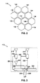
- Figs. 2, 3, 4A and 4B illustrate a simplified base station network 110 and more detailed aspects of base stations 112 and 126. These figures also illustrate the concept of neighboring base stations. The components of the figures will be described generally first and then in more detail with respect to the dynamic channel allocation apparatus and method of the present invention.
- the base station network 110 of Fig. 2 includes base stations 112, 120, 122, 124, 126, 128, 130, 132, 134, and 136.
- the base stations would typically be hardwired to a mobile switching center, such as mobile switching center 12, as shown in Fig. 1.
- the network 110 includes a plurality of further base stations which are not shown, and which may number in the hundreds, thousands, or more.
- Each base station has base stations adjacent to it, which in this example will be defined as its "neighboring" base stations.
- base station 112 has neighboring base stations 120, 122, 124, 126, 128, and 130 while base station 126 has neighboring base stations 112, 124, 128, 132, 134, and 136.
- each base station is not permitted to use any of the frequency channel pairs which are used by any of its neighboring base stations.
- the "neighbors" are defined as the base stations which are adjacent another base station.
- base station 112 is not permitted to use any of the frequency channel pairs being used by base stations 120, 122, 124, 126, 128, and 130.
- This constraint is known as a reuse constraint of 1-cell buffering. The concurrent use of frequency channels by a base station and one of its neighboring base stations results in poor communications between mobile units and base stations.
- the 1-cell reuse constraint discussed is exemplary and a higher reuse constraint such as 2-cell may be used to define "neighbors".
- base station 112 for example, would also not be able to use a frequency channel being used by base stations 132, 134, or 136.
- the "neighboring" base stations of base station 112 would include base stations 132, 134, and 136.
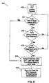
- Fig. 3 shows a more detailed diagram of the base station 112, which comprises a receiving antenna 212, a transmitting antenna 214, a bandpass filter 216, a voltage controlled oscillator 218, an amplifier 220, a processor 224, an output port 226, an input port 228, and a storage device 230.
- the output port 226 and input port 228 are hardwired through communication lines to a mobile switching center such as the switching center 12 of Fig. 1.
- Voltage controlled oscillator 218 has a data signal input line 222.
- Processor 224 further comprises control lines 221 and 223, data signal input line 225, and data signal output line 227.
- the input port 226 and output port 228 may also be combined in a single bidirectional input/output port.
- the general operation of a base station, such as base station 112, in communicating with a mobile unit will now be described.
- the processor 224 examines data storage device 230 to determine which channel pairs have been assigned by base station 112, and then cycles through the assigned channel pairs communicating with the respective mobile units.
- processor 224 tunes bandpass filter 216 to the uplink frequency channel of channel pair "B" through control line 221.
- a signal having that uplink frequency is received by receiver antenna 212 from a mobile unit, it is passed through bandpass filter 216, amplified by amplifier 220 and sent to processor 224.
- Processor 224 preferably includes a device such as an analog to digital converter to change the analog signal received at the receiver antenna 212 into a digital signal. The digital signal can then be sent from the base station either directly to another mobile unit or from the base station to a mobile switching center and then to another mobile unit or to a hardwired device, as known in the art.
- the processor 224 sets the voltage controlled oscillator 218, through control line 223, to the downlink frequency of the assigned frequency channel pair, which in this example is channel pair "B".
- the processor 224 then sends digital signals out on its data signal output line 227.
- the digital signals are received at the data signal input 222 of the voltage controlled oscillator 218 and cause the oscillations to cease or continue depending respectively on whether a "1" or "0" digital signal is output.
- Other techniques known in the art for transmitting digital signals can also be used.
- the processor 224 can change the receive frequency channel simply by tuning the bandpass filter 216 to a different frequency.
- the processor 224 can change the transmitted frequency channel by changing the control signal on control line 223 to change the frequency of the voltage controlled oscillator 218.
- the processor 224 thus can communicate through a plurality of frequency channel pairs to allow the base station to communicate with a plurality of mobile units.
- each transmitting antenna can be coupled to a filter or oscillator which is set to transmit a specific frequency.
- Each receiver can be coupled to a filter which is set to a particular frequency.
- the processor can communicate with a plurality of mobile units at virtually the same time.
- a single receiving antenna coupled to a plurality of filters and a single transmitting antennas coupled to a plurality of filters or oscillators can be used.
- Figs. 4A and 4B show exemplary augmented channel pair occupancy (ACO) tables 300 and 310 for the base stations 112 and 126, respectively, of Fig. 2.
- ACO augmented channel pair occupancy
- the table 300 is located in the storage device 230 of Fig. 3.
- the ACO table 300 includes channel pair occupancy data 302 and channel pair availability data 304 for base station 112 and its neighboring base stations, 120, 122, 124, 126, 128, and 130, where its "neighbors" are defined by a 1-cell buffering or 1-base station buffering reuse constraint.
- Channel pair occupancy data 302 indicates whether a specific base station is using one of eight channel pairs A-H.
- the row for base station 112 shows an "x" under columns labelled “B” and “E”. This indicates that base station 112 is using channel pairs "B" and "E” (i.e. the base station is communicating with one mobile unit on channel pair “B” and another mobile unit on channel pair “E” ).
- the row for base station 120 shows an "x” under columns labelled “A”, “D”, and “G” and this indicates that base station 120 is using channel pairs "A", “D”, and “G”.
- Channel pair occupancy information is similarly shown for the other neighboring base stations of base station 112, namely base stations 122, 124, 126, 128, and 130.
- the channel pair availability data 304 of the ACO table 300 indicates whether there is a channel pair available for a particular base station.
- the number of channel pairs available to a base station depends on both the channel pairs that the base station is using and the channel pairs its neighboring base stations are using. For example, the row for base station 112 shows that base station 112 currently has "0" channel pairs available because every channel pair A-H is being used either by base station 112 or by one of its neighboring base stations 120, 122, 124, 126, 128, and 130.
- the lack of available channel pairs can be seen by observing that there is an "x" in each frequency channel pair column "A" through "H” in ACO table 300.
- the channel pair availability data for neighboring base stations 120, 122, 124, 126, 128, and 130 which is shown in the channel pair availability data 304, cannot be determined by looking at the channel pair occupancy data 302.
- the channel pair availability data for each of neighboring base stations 120, 122, 124, 126, 128, and 130 comes from their own ACO tables.
- the ACO table for base station 126 is shown in Fig. 4B.
- the ACO tables for base stations 120, 122, 124, 128, and 130 will be similar, however their neighboring base stations will differ.
- the ACO table 310 located in base station 126, and shown in Fig. 4B, will now be described.
- the ACO table 310 has the same format as the ACO table 300 of Fig. 4A.
- the ACO table 310 includes channel pair occupancy data 312 for channel pairs "A" through “H” similar to the channel pair occupancy data 302 for channel pairs "A" through “H” in ACO table 300.
- the ACO table 310 also includes channel pair availability data 314 similar to the channel pair availability data 304 in Fig. 4A.
- table 300 for base station 112 has neighbors 120, 122, 124, 126, 128, and 130 while base station 126 has neighbors 112, 124, 128, 132, 134, and 136.
- channel pair availability data 314 of ACO table 310 It can be seen by examining the channel pair availability data 314 of ACO table 310 that base station 126 has one channel pair available. This can also be seen by examining the columns of the channel pair occupancy data 312. The column for channel pair "D” does not have an "x" in it and this indicates that channel pair "D” is not being used by base station 126 or any of its neighboring base stations 112, 124, 128, 132, 134, or 136.
- the number of channel pairs available to the other base stations 120, 122, 124, 128, 130, 132, 134, and 136 can be determined by examining the channel pair occupancy data of their ACO tables in the same manner as determined for base station 112 and 126.
- the number of channel pairs available to each neighbor is reported to base station 112 from its neighboring base stations 120, 122, 124, 126, 128, and 130 and stored as the channel pair availability data 304 of the table 300.
- base station 126 has one free channel pair, channel pair "D", which is not being used by base station 126 or any of its neighboring base stations.
- Base station 126 sends a digital signal indicating the number of channels available, in this case "1", to the mobile switching center, such as the mobile switching center 12 in Fig. 1, which sends this digital signal to base station 112 via input port 228 shown in Fig. 3.
- Base station 112 records the information in the channel availability data 304 of its ACO table 300 in the row for base station 126, as the number "1".
- a channel pair access request signal from a mobile unit is received by the receiver 212, shown in Fig. 3.
- the request signal is filtered by bandpass filter 216 which is tuned to an access signal frequency channel, amplified by amplifier 220, and processed by processor 224.
- the processor 224 determines that a channel pair access request has been received and then determines whether base station 112 has an available channel pair by examining the row for base station 112 in the channel pair availability data 304 of the ACO table 300. Alternatively, the channel pair occupancy data 302 could be examined.
- the requesting mobile unit would be assigned that channel pair. Communications between the mobile unit and the base station 112 would then take place on that channel pair. In addition, the channel occupancy data 302 and the channel availability data 304 would be updated.
- the channel pair availability data 304 in Fig. 4A shows "0" available channel pairs in the row for base station 112.
- Processor 224 determines that there are “0” available channel pairs for base station 112 and next examines the channel pair occupancy data 302 in the ACO table 300 to determine if there is a single-user channel pair which is not being used by base station 112 and which is being used by only one of the neighboring base stations 120, 122, 124, 126, 128, and 130. In this case channel pairs "D” and “F” are only being used by base stations 120 and 126 respectively. This can be seen by the single “x” in the "D” and "F” columns of ACO table 300 of Fig. 4A.
- Processor 224 then examines the channel pair availability data 304 to determine whether there is a channel pair available to either base station 120 or base station 126. In this case, the row for base station 120 shows "0" available channel pairs and the row for base station 126 shows "1" available channel pair. Thus, if base station 126 is bumped from channel pair "F" it will have another available channel pair.
- Processor 224 then transmits a seize signal to the output port 226 to send to the mobile switching center to inform base station 126 that base station 112 will now be using channel pair "F".
- Base station 126 receives the seize signal from the mobile switching center and changes the channel pair assignment to its other available channel pair, channel pair "D”.
- the processor 224 of base station 112 assigns channel pair "F" to the requesting mobile unit. and updates the ACO table 300 to reflect changes in channel pair occupancy and channel pair availability.
- Both base stations 112 and 126 also send data to their respective output ports, such as output port 226 for base station 112, indicating the change in channel assignment so that neighboring base stations can update their own ACO tables.
- the data is sent to the mobile switching center, such as mobile switching center 12 in Fig. 1, which in turn sends it to the appropriate neighboring base stations.
- FIG. 5 shows a flow chart 400 comprising blocks 402, 404, 406, 408, 410, and 412.
- a mobile channel pair access request is received at a particular base station, such as base station 112, at block 402.
- the channel pair availability data in the ACO table for a particular base station, for example for base station 112, data 304 in table 300, is checked at block 404 to determine if a channel pair is available to that base station. If there is an available channel pair, the available channel pair or one of the available channel pairs is assigned to the mobile unit in block 410. If there are a plurality of available channel pairs, a particular available channel pair can be assigned on a random basis.
- data concerning the channel pair assignment is sent out to neighboring base stations, which for base station 112 would comprise base stations 120, 122, 124, 126, and 130.
- the data is preferably digital and is first sent to a mobile switching center, such as mobile switching center 12 in Fig. 1, via an output port, such as output port 226 in Fig. 3, and then to the appropriate base station.
- the channel pair occupancy data in the ACO table is checked in block 406 to determine if there is a single-user channel pair which is not being used by this base station and which is being used by only one neighboring base station. If there is no such channel pair, the method loops back to block 404 to begin looking for available channel pairs again.
- the mobile unit access request also known as a "call" can also be blocked instead of looping back to try again.
- the channel pair availability data of the ACO table is next checked in block 408 to determine if the neighboring base stations which are using these single user channel pairs have channel pairs available to them. If one of these neighboring base stations has an available channel pair, the current base station seizes the single user channel pair and assigns it to the requesting mobile unit in block 410. Digital signals specifying that this base station is now using the seized channel pair are sent out to the neighboring base stations such as the stations 120, 122, 124, 126, 128, and 130, in block 412. The neighboring base station which was formerly using the seized channel pair, such as station 126, will stop using the seized channel pair, such as channel pair "F", and use its available channel pair, such as channel pair "D".
- the ACO tables can be stored in an array or table of memory locations in known memory devices such as a RAM.
- the RAM can store digital "1"'s to correspond to the "x"'s of the channel occupancy data such as data 302 shown in Fig. 4A.
- the tables can be updated simply by writing over a location in RAM.
- the RAM can also store the numbers indicating the channel availability data such as the data 304 shown in Fig. 4A.
- Fig. 6 illustrates another embodiment of the present invention.
- the ACO table information from all base stations in a specified area is contained in a mobile switching center 540.
- Fig. 6 illustrates base stations 511, 512, 513, 514, 515, and 516, and mobile switching center 540.
- the mobile switching center 540 is connected to numerous further base stations which are not shown and which may number in the hundreds or thousands.
- the mobile switching center 540 includes a data bus 542, a processor 544 and storage device 546, such as a RAM, for storing channel pair occupancy and availability data.
- Base stations 511, 512, 513, 514, 515, and 516 are connected to the data bus 542 of the processor 544 by bidirectional lines 531, 532, 533, 534, 535 and 536 respectively.
- Fig. 6 is a simplified example in which it will be assumed that each base station has only two neighboring base stations, one to its right and one to its left.
- base station 514 has two neighboring base stations, 513 and 515.
- Base station 513 similarly has two neighboring base stations 512 and 514, and base station 515 similarly has two neighbors 514 and 516.
- Storage device 546 is adaptable for storing sets of data concerning channel pair occupancy and channel pair availability for base stations 511-516.
- Each set of data may be in the form of an ACO table for each base station similar to the table shown in Figs. 4A and 4B.
- Figs. 7A, 8A, 9A, and 10A show ACO tables for base stations 514, 513, 515 and 512, respectively, which are all located in the single mobile switching center 540.
- Figs. 7B, 8B, 9B, and 10B show the same tables after channel pair assignment.
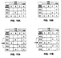
- the sets of data may also be in a single table as shown in Fig. 11A before channel pair assignment and Fig. 11B after channel pair assignment.
- Figs. 7A-B, 8A-B, 9A-B, and 10A-B include ACO tables 700, 800, 900, and 1000 respectively.
- the ACO tables 700, 800, 900, and 1000 further comprise channel pair occupancy data 702, 802, 902, and 1002 and channel pair availability data 704, 804, 904, and 1004 respectively.
- Each ACO table contains data similar to that of Figs. 4A and 4B.
- Fig. 7A shows channel pair occupancy data 702 for three channel pairs "A", “B", and “C".
- an "x" under those columns indicates that a base station is using that frequency channel pair to communicate with a mobile unit.
- Fig. 7A shows that base station 514 is using channel pair "A”, base station 513 is using channel pair "B", and base station 515 is using channel pair "C”.
- Fig. 7A also includes channel availability data 704 which includes the number of channels available to a particular base station. The channel availability data is labeled "#”.
- base stations 514, 513, and 515 have "0", "1” and “0” channels available respectively.
- the channel pair allocation operation of the present invention will be described for the multiple tabular embodiment in a single mobile switching center 540 with reference to Figs. 6-10.
- a mobile unit requests access to a channel pair, for example from the base station 514
- the base station 514 sends a request to the processor 544 of the mobile switching center 540 through bidirectional line 534 and the data bus 542.
- the processor 544 then examines the channel pair availability data for base station 514 in storage device 546 to determine if there are available channels.
- the processor 544 examines the row for base station 514 of the channel pair availability data 704, shown in Fig. 7A.
- the processor 544 checks the channel pair occupancy data 702 in the ACO table 700 in Fig. 7A to see if there are any single-user channel pairs which are not being used by base station 514 and which are being used by only one neighboring base station.
- the columns for channel pairs "B” and “C” of the channel pair occupancy data 702 show that channel pairs "B" and "C” are being used by only base stations 513 and 515 respectively.
- the processor 544 next examines the rows for base station 513 and 515 of channel pair availability data 704 to determine whether either of the base stations 513 or 515 has any available channel pairs.
- the channel pair availability data 704 shows that the base station 513 has “1" channel pair available and base station 515 has “0" channel pairs available. Therefore, the processor 544 assigns base station 514, and the requesting mobile unit, channel pair "B". The assignment data is sent out to base station 514 from processor 544 through data bus 542 and bidirectional line 534.
- Base station 513 is "bumped" from channel pair "B” and assigned a new channel pair by first examining the channel pair occupancy data 802 of its ACO table 800 in Fig. 8A to determine which channel pair is available.
- the column for channel pair “C” has no “x"'s in it indicating that channel pair "C” is currently not being used by base station 513 or its neighboring base stations 514 and 512.
- channel pair "C” is assigned to base station 513.
- the assignment data is sent out to base station 513 from processor 544 through data bus 542 and bidirectional line 533.
- the channel pair occupancy data 702 and 802 for base stations 514 and 513 as shown in Figs. 7A and 8A, are modified after channel pair "B" is assigned to base station 514, base station 513 is bumped from channel pair "B", and channel pair "C” is assigned to base station 513.
- the updated ACO data after all of these operations are complete are shown in Figs. 7B and 8B.
- the channel pair occupancy data in the ACO tables for the neighboring base stations of base stations 513 and 514 are also updated.
- the original ACO tables 900 and 1000 for base stations 515 and 512 are shown in Figs 9A and 10A, respectively.
- the updates of those tables are shown in Figs. 9B and 10B.
- the data can be updated simply by writing over the contents of memory locations in RAM.
- the channel pair occupancy data of the ACO tables of all the neighbors of that base station should be updated.
- the channels available to a particular base station change, such as the change observed in the row for base station 513, from Fig. 7A to Fig. 7B in the channel availability data 704 column, the channel availability data of the ACO tables of all of that base station's neighbors should be updated. In this case, the neighbors would be base station 514 and 512.
- Channel availability data for a particular base station can be determined by processor 544 examining the channel occupancy data as described for Figs. 4A and 4B. For example, for base station 514, the table in Fig. 7A is examined by processor 544 to determine that there is an "x" in each channel column and that therefore there are no channel pairs available. This data is stored as the number "0" as shown in data 704 in the row for base station 514 of Fig. 7A.
- the number of base stations hardwired to a mobile switching center is usually much larger than the number of neighboring base stations surrounding any one base station.
- the present invention provides a dynamic channel allocation technique which operates only on a base station and its neighbors and not the entire network.
- Fig. 6 shows only 6 base stations connected to the mobile switching center 540, there are typically hundreds or thousands of such base stations.
- the data shown in Figs. 7A-B, 8A-B, 9A-B, and 10A-B is duplicative.
- the row for base station 514 in Fig. 7A is the same as the row for base station 514 in Fig. 8A.
- the tables of Figs. 7A, 8A, 9A, 10A are located in the same mobile switching center, it is preferable to combine the tables into one combined table as shown in Figs. 11A-B.
- duplicative data can be eliminated and substantial memory savings in the mobile switching center are achieved.
- changes in channel occupancy data and channel availability data need only be made once.
- Channel pair assignment in the single table case located in a single mobile switching center functions in largely the same manner as the multiple tabular case located in a single mobile switching center, described with reference to Figs. 7A-B, 8A-B, 9A-B, 10A-B.
- the processor 544 examines the ACO tabular information for a particular base station it looks at a particular set of data in the combined table.
- the set of data labelled 1106, in Figs. 11A and 11B would be examined for channel pair occupancy and availability data, to determine if a channel could be assigned.
- the data labelled 1106 is exactly the same as the table shown in Fig. 7A.
- base stations includes microcells such as disclosed in “Microcells in Personal Communications Systems,” IEEE Communications Magazine, December 1992.
Landscapes
- Engineering & Computer Science (AREA)
- Computer Networks & Wireless Communication (AREA)
- Signal Processing (AREA)
- Mobile Radio Communication Systems (AREA)
Applications Claiming Priority (2)
| Application Number | Priority Date | Filing Date | Title |
|---|---|---|---|
| US15650693A | 1993-11-23 | 1993-11-23 | |
| US156506 | 1993-11-23 |
Publications (3)
| Publication Number | Publication Date |
|---|---|
| EP0654952A2 true EP0654952A2 (fr) | 1995-05-24 |
| EP0654952A3 EP0654952A3 (fr) | 1999-03-17 |
| EP0654952B1 EP0654952B1 (fr) | 2003-10-29 |
Family
ID=22559855
Family Applications (1)
| Application Number | Title | Priority Date | Filing Date |
|---|---|---|---|
| EP94308473A Expired - Lifetime EP0654952B1 (fr) | 1993-11-23 | 1994-11-16 | Procédé et dispositif pour l'affectation dynamique de canal pour communication "sans fil" |
Country Status (5)
| Country | Link |
|---|---|
| US (2) | US6178329B1 (fr) |
| EP (1) | EP0654952B1 (fr) |
| JP (1) | JP2781142B2 (fr) |
| CA (1) | CA2118273C (fr) |
| DE (1) | DE69433275T2 (fr) |
Cited By (15)
| Publication number | Priority date | Publication date | Assignee | Title |
|---|---|---|---|---|
| DE19625856A1 (de) * | 1996-06-27 | 1997-09-25 | Siemens Ag | Verfahren und Anordnung zur Kanalauswahl bei zellularen Funksystemen |
| WO1997032406A3 (fr) * | 1996-03-01 | 1997-10-23 | Nokia Telecommunications Oy | Procede de commande d'une station de base et station de base |
| AT1804U1 (de) * | 1995-07-12 | 1997-11-25 | Plehn Juergen Dr | Verfahren zur zuweisung einer frequenz zu einer sende-/empfangseinrichtung |
| EP0841827A2 (fr) * | 1996-11-08 | 1998-05-13 | Lucent Technologies Inc. | Système fixe de ligne d'abonné sans fil à base de TDM |
| WO1998000992A3 (fr) * | 1996-06-28 | 1998-06-25 | Harris Corp | Ameliorations concernant un procede et un appareil permettant de determiner la synchronisation des symboles dans un systeme de transmission sans fil, utilisant un canal de commande reutilisable et reduisant la puissance |
| WO1998000997A3 (fr) * | 1996-06-28 | 1998-07-09 | Harris Corp | Perfectionnements d'un systeme polyvalent de telecommunications hertziennes et procede de reaffectation dynamique des frequences |
| US5887255A (en) * | 1996-06-28 | 1999-03-23 | Marris Corporation | Multiple use wireless communications system and method |
| WO1999048255A1 (fr) * | 1998-03-19 | 1999-09-23 | Telefonaktiebolaget Lm Ericsson (Publ) | Ordonnancement selon l'efficacite de lien dans des systemes de radiocommunications de donnees |
| EP1253794A1 (fr) * | 2001-04-24 | 2002-10-30 | Siemens Aktiengesellschaft | Méthode et système pour fournir un accés à des stations dans un moyen de communication commun |
| EP1347600A3 (fr) * | 2002-03-22 | 2003-11-05 | NEC Infrontia Corporation | Stations de base LAN sans fil capable de mise en oeuvre d' une adaption automatique des canaux radio |
| WO2004016023A1 (fr) * | 2002-08-07 | 2004-02-19 | Huawei Technologies Co.,Ltd. | Procede de gestion des acces communications |
| WO2004060009A1 (fr) * | 2002-12-27 | 2004-07-15 | Nortel Networks Limited | Procede et dispositif pour ameliorer une caracteristique de signal de transmission d'un signal de liaison descendante dans un systeme de communication sans fil a acces direct par repartition dans le temps |
| EP1775981A1 (fr) * | 2005-10-13 | 2007-04-18 | Mitsubishi Electric Information Technology Centre Europe B.V. | Procédé pour déterminer si une première cellule gérée par une première station de base est voisine d'une deuxième cellule gérée par une deuxième station de base |
| WO2009024614A3 (fr) * | 2007-08-22 | 2009-05-14 | Nokia Siemens Networks Oy | Échange de stratégies de programme pour coordination d'interférence |
| GB2456663A (en) * | 2008-01-23 | 2009-07-29 | Toshiba Kk | A base station controller assigns a radio channel that is unused in the base station requesting the radio channel assignment and in the adjacent base station |
Families Citing this family (39)
| Publication number | Priority date | Publication date | Assignee | Title |
|---|---|---|---|---|
| US6400752B1 (en) * | 1994-09-29 | 2002-06-04 | Ricoh Company, Ltd. | Wireless computer network communication system and method which determines an available spreading code |
| JPH10322760A (ja) | 1997-05-21 | 1998-12-04 | Toshiba Corp | セルラ無線システム |
| WO1999049687A2 (fr) * | 1998-03-26 | 1999-09-30 | Koninklijke Philips Electronics N.V. | Reseau de communications a protocole d'acces ameliore |
| US6539228B1 (en) * | 1998-04-24 | 2003-03-25 | British Telecommunications Public Limited Company | Channel allocation in cellular telephony |
| US6496490B1 (en) * | 1998-07-09 | 2002-12-17 | Lucent Technologies Inc. | Method for dynamically allocating carriers in a wireless packet network, with reuse of carriers |
| US6970709B1 (en) * | 1998-10-15 | 2005-11-29 | Airnet Communications Corporation | Method for dynamic allocation of wireless base station DSP resources |
| CN1204779C (zh) * | 1999-12-30 | 2005-06-01 | 英国电讯有限公司 | 对无线电收发信机的信道分配 |
| US7260620B1 (en) * | 2000-01-05 | 2007-08-21 | Cisco Technology, Inc. | System for selecting the operating frequency of a communication device in a wireless network |
| US6732163B1 (en) * | 2000-01-05 | 2004-05-04 | Cisco Technology, Inc. | System for selecting the operating frequency of a communication device in a wireless network |
| US8321542B1 (en) | 2000-05-05 | 2012-11-27 | Ipr Licensing, Inc. | Wireless channel allocation in a base station processor |
| FI110153B (fi) * | 2000-05-12 | 2002-11-29 | Nokia Corp | Menetelmä langattoman verkon radiokanavien jakamiseksi |
| US6731953B1 (en) * | 2000-06-30 | 2004-05-04 | Nortel Networks Limited | Apparatus and method for asymmetrical frequency spectrum utilization in a wireless network |
| US7194269B2 (en) * | 2000-10-30 | 2007-03-20 | Her Majesty The Queen In Right Of Canada, As Represented By The Minister Of Industry | Method and wireless communication hub for data communications |
| US6947748B2 (en) | 2000-12-15 | 2005-09-20 | Adaptix, Inc. | OFDMA with adaptive subcarrier-cluster configuration and selective loading |
| CN100539519C (zh) * | 2001-04-24 | 2009-09-09 | 诺基亚西门子通信有限责任两合公司 | 将站接入到公共传输媒体的方法和用于实施这种方法的网络站 |
| US7127175B2 (en) * | 2001-06-08 | 2006-10-24 | Nextg Networks | Method and apparatus for multiplexing in a wireless communication infrastructure |
| US6826163B2 (en) | 2001-06-08 | 2004-11-30 | Nextg Networks | Method and apparatus for multiplexing in a wireless communication infrastructure |
| US6826164B2 (en) | 2001-06-08 | 2004-11-30 | Nextg Networks | Method and apparatus for multiplexing in a wireless communication infrastructure |
| US20020191565A1 (en) * | 2001-06-08 | 2002-12-19 | Sanjay Mani | Methods and systems employing receive diversity in distributed cellular antenna applications |
| JP2003032725A (ja) * | 2001-07-18 | 2003-01-31 | Ntt Docomo Inc | 移動通信システムにおける無線基地局選択方法及びシステム並びに無線基地局 |
| US20040198453A1 (en) * | 2002-09-20 | 2004-10-07 | David Cutrer | Distributed wireless network employing utility poles and optical signal distribution |
| JP4289855B2 (ja) * | 2002-09-20 | 2009-07-01 | 京セラ株式会社 | 無線基地装置、参照信号割当方法および参照信号割当プログラム |
| US20050125420A1 (en) * | 2003-12-03 | 2005-06-09 | Allen Tsz-Chiu Wong | System and method of operating the system that prevents multiple channels from continuously being sent to the same set top box |
| US7272375B2 (en) * | 2004-06-30 | 2007-09-18 | Silicon Laboratories Inc. | Integrated low-IF terrestrial audio broadcast receiver and associated method |
| JP4455354B2 (ja) | 2005-01-26 | 2010-04-21 | 株式会社エヌ・ティ・ティ・ドコモ | 移動通信システム |
| JP2006271432A (ja) * | 2005-03-28 | 2006-10-12 | Fujinon Corp | 電子内視鏡装置 |
| CN1893343B (zh) * | 2005-07-05 | 2010-05-05 | 上海原动力通信科技有限公司 | 多载波hsdpa下行业务信道资源分配及数据传输的方法 |
| US7835750B2 (en) * | 2005-10-07 | 2010-11-16 | Samsung Electronics Co., Ltd. | Multi-carrier wireless network using flexible fractional frequency reuse |
| US7840187B2 (en) * | 2005-11-10 | 2010-11-23 | Samsung Electronics Co., Ltd. | System and method for dynamic frequency selection based on spectrum etiquette |
| US8805294B2 (en) * | 2005-11-12 | 2014-08-12 | Via Telecom Co., Ltd. | System and method for feeding back information to a user-terminal from multiple hubs |
| CN101001438B (zh) * | 2006-01-10 | 2010-12-08 | 华为技术有限公司 | 相邻基站间协商工作信道的方法 |
| JP2007266697A (ja) * | 2006-03-27 | 2007-10-11 | Toyota Infotechnology Center Co Ltd | 無線通信方法、無線通信装置、および無線通信プログラム |
| US7596461B2 (en) * | 2007-07-06 | 2009-09-29 | Cisco Technology, Inc. | Measurement of air quality in wireless networks |
| US8305971B2 (en) * | 2009-01-13 | 2012-11-06 | Cisco Technology, Inc. | Utilizing persistent interference information for radio channel selection |
| DE102009052936B8 (de) | 2009-11-12 | 2012-05-10 | Andrew Wireless Systems Gmbh | Master-Einheit, Remote-Einheit sowie Multiband-Übertragungssystem |
| WO2012039858A2 (fr) * | 2010-09-22 | 2012-03-29 | Xg Technology, Inc. | Réseaux cellulaires auto-organisateurs |
| CN102104875B (zh) * | 2010-12-30 | 2016-03-09 | 青海西部矿业科技有限公司 | 一种新型认知无线电多信道mac协议方法 |
| US20160374092A1 (en) * | 2014-03-05 | 2016-12-22 | Intel Corporation | Techniques for determining channel allocations |
| US10863543B2 (en) * | 2017-12-01 | 2020-12-08 | Qualcomm Incorporated | Subband based uplink access for NR-SS |
Family Cites Families (12)
| Publication number | Priority date | Publication date | Assignee | Title |
|---|---|---|---|---|
| US3764915A (en) * | 1971-06-25 | 1973-10-09 | Bell Telephone Labor Inc | Dynamic program control for channel assignment in mobile communication systems |
| EP0283683B1 (fr) * | 1987-03-20 | 1994-01-12 | Hitachi, Ltd. | Système de communication sans-fil portable et méthode |
| JP2545466B2 (ja) * | 1989-08-24 | 1996-10-16 | 日本電信電話株式会社 | 移動通信位置登録方法 |
| US5257398A (en) * | 1990-02-27 | 1993-10-26 | Motorola, Inc. | Hopped-carrier dynamic frequency reuse |
| US5276908A (en) * | 1990-10-25 | 1994-01-04 | Northern Telecom Limited | Call set-up and spectrum sharing in radio communication on systems with dynamic channel allocation |
| US5134709A (en) * | 1990-12-14 | 1992-07-28 | At&T Bell Laboratories | Process and apparatus for flexible channel assignment in cellular radiotelephone systems |
| JPH0568284A (ja) * | 1991-09-09 | 1993-03-19 | Nippon Telegr & Teleph Corp <Ntt> | 移動通信における無線チヤネル制御方式 |
| JPH05206933A (ja) * | 1992-01-27 | 1993-08-13 | Fujitsu Ltd | 無線チャネル割り当て方式 |
| US5276730A (en) * | 1992-04-30 | 1994-01-04 | At&T Bell Laboratories | Access method for distributed dynamic channel allocation in microcells |
| AU670955B2 (en) * | 1992-08-04 | 1996-08-08 | Koninklijke Philips Electronics N.V. | Mobile radio system |
| JP2507959B2 (ja) * | 1993-04-26 | 1996-06-19 | 日本電気株式会社 | 無線ゾ―ン選択方式 |
| CA2123736C (fr) * | 1993-10-04 | 1999-10-19 | Zygmunt Haas | Systeme cellulaire |
-
1994
- 1994-10-17 CA CA002118273A patent/CA2118273C/fr not_active Expired - Fee Related
- 1994-11-16 DE DE69433275T patent/DE69433275T2/de not_active Expired - Lifetime
- 1994-11-16 EP EP94308473A patent/EP0654952B1/fr not_active Expired - Lifetime
- 1994-11-22 JP JP6287030A patent/JP2781142B2/ja not_active Expired - Lifetime
-
1997
- 1997-06-24 US US08/881,625 patent/US6178329B1/en not_active Expired - Lifetime
-
2000
- 2000-10-16 US US09/690,135 patent/US6580913B1/en not_active Expired - Fee Related
Cited By (35)
| Publication number | Priority date | Publication date | Assignee | Title |
|---|---|---|---|---|
| AT1804U1 (de) * | 1995-07-12 | 1997-11-25 | Plehn Juergen Dr | Verfahren zur zuweisung einer frequenz zu einer sende-/empfangseinrichtung |
| WO1997032406A3 (fr) * | 1996-03-01 | 1997-10-23 | Nokia Telecommunications Oy | Procede de commande d'une station de base et station de base |
| US6317423B1 (en) | 1996-03-01 | 2001-11-13 | Nokia Telecommunications Oy | Method for controlling a base station, and base station |
| DE19625856A1 (de) * | 1996-06-27 | 1997-09-25 | Siemens Ag | Verfahren und Anordnung zur Kanalauswahl bei zellularen Funksystemen |
| CN1094023C (zh) * | 1996-06-28 | 2002-11-06 | 哈里公司 | 对或者关于一个多用户无线通信系统和通信频率的动态分配方法的改进 |
| WO1998000992A3 (fr) * | 1996-06-28 | 1998-06-25 | Harris Corp | Ameliorations concernant un procede et un appareil permettant de determiner la synchronisation des symboles dans un systeme de transmission sans fil, utilisant un canal de commande reutilisable et reduisant la puissance |
| WO1998000997A3 (fr) * | 1996-06-28 | 1998-07-09 | Harris Corp | Perfectionnements d'un systeme polyvalent de telecommunications hertziennes et procede de reaffectation dynamique des frequences |
| US5887255A (en) * | 1996-06-28 | 1999-03-23 | Marris Corporation | Multiple use wireless communications system and method |
| EP0841827A2 (fr) * | 1996-11-08 | 1998-05-13 | Lucent Technologies Inc. | Système fixe de ligne d'abonné sans fil à base de TDM |
| WO1999048255A1 (fr) * | 1998-03-19 | 1999-09-23 | Telefonaktiebolaget Lm Ericsson (Publ) | Ordonnancement selon l'efficacite de lien dans des systemes de radiocommunications de donnees |
| US6236656B1 (en) | 1998-03-19 | 2001-05-22 | Telefonaktiebolaget Lm Ericsson (Publ) | Link-efficiency based scheduling in radio data communications systems |
| EP1253794A1 (fr) * | 2001-04-24 | 2002-10-30 | Siemens Aktiengesellschaft | Méthode et système pour fournir un accés à des stations dans un moyen de communication commun |
| EP1347600A3 (fr) * | 2002-03-22 | 2003-11-05 | NEC Infrontia Corporation | Stations de base LAN sans fil capable de mise en oeuvre d' une adaption automatique des canaux radio |
| US7193975B2 (en) | 2002-03-22 | 2007-03-20 | Nec Infrontia Corporation | Wireless LAN base station capable of carrying out automatic matching for radio channels |
| AU2002309010B2 (en) * | 2002-03-22 | 2007-10-04 | Nec Corporation | Wireless Lan Base Station Capable of Carrying Out Automatic Matching for Radio Channels |
| WO2004016023A1 (fr) * | 2002-08-07 | 2004-02-19 | Huawei Technologies Co.,Ltd. | Procede de gestion des acces communications |
| US7602761B2 (en) | 2002-08-07 | 2009-10-13 | Huawei Technologies, Co. Ltd. | Call access control method |
| DE10393031B4 (de) * | 2002-08-07 | 2013-12-05 | Huawei Technologies Co., Ltd. | Rufzugriffssteuerverfahren |
| WO2004060009A1 (fr) * | 2002-12-27 | 2004-07-15 | Nortel Networks Limited | Procede et dispositif pour ameliorer une caracteristique de signal de transmission d'un signal de liaison descendante dans un systeme de communication sans fil a acces direct par repartition dans le temps |
| US8159998B2 (en) | 2002-12-27 | 2012-04-17 | Rockstar Bidco Lp | Method and apparatus for improving a transmission signal characteristic of a downlink signal in a time division multiple access wireless communication system |
| EP1775981A1 (fr) * | 2005-10-13 | 2007-04-18 | Mitsubishi Electric Information Technology Centre Europe B.V. | Procédé pour déterminer si une première cellule gérée par une première station de base est voisine d'une deuxième cellule gérée par une deuxième station de base |
| US8095136B2 (en) | 2005-10-13 | 2012-01-10 | Mitsubishi Electric Corporation | Method for determining if a first cell managed by a first base station is neighbour of a second cell managed by a second base station |
| US8396478B2 (en) | 2005-10-13 | 2013-03-12 | Mitsubishi Electric Corporation | First base station managing a neighboring condition and cell area operation of a cell area, and system for managing a neighboring condition and cell area operation of a cell area |
| EP2247136A3 (fr) * | 2005-10-13 | 2011-01-05 | Mitsubishi Electric R&D Centre Europe B.V. | Procédé pour déterminer si une première cellule gérée par une première station de base est voisine d'une deuxième cellule gérée par une deuxième station de base |
| EP2247135A3 (fr) * | 2005-10-13 | 2011-01-05 | Mitsubishi Electric R&D Centre Europe B.V. | Procédé pour déterminer si une première cellule gérée par une première station de base est voisine d'une deuxième cellule gérée par une deuxième station de base |
| US8073445B2 (en) | 2005-10-13 | 2011-12-06 | Mitsubishi Electric Corporation | Method for determining if a first cell managed by a first base station is neighbour of a second cell managed by a second base station |
| US8498253B2 (en) | 2007-08-22 | 2013-07-30 | Nokia Siemens Networks Oy | Exchange of scheduling strategies for interference coordination |
| RU2485718C2 (ru) * | 2007-08-22 | 2013-06-20 | Нокиа Сименс Нетворкс Ой | Обмен стратегиями планирования для координации помех |
| CN101836472A (zh) * | 2007-08-22 | 2010-09-15 | 诺基亚西门子通信公司 | 用于干扰协调的调度策略的交换 |
| WO2009024614A3 (fr) * | 2007-08-22 | 2009-05-14 | Nokia Siemens Networks Oy | Échange de stratégies de programme pour coordination d'interférence |
| CN101836472B (zh) * | 2007-08-22 | 2014-11-26 | 诺基亚通信公司 | 用于干扰协调的调度策略的交换 |
| EP3790302A1 (fr) * | 2007-08-22 | 2021-03-10 | Wireless Future Technologies Inc. | Échange de stratégies de programme pour coordination d'interférence |
| EP4482244A3 (fr) * | 2007-08-22 | 2025-03-19 | Wireless Future Technologies Inc. | Échange de stratégies de planification pour la coordination d'interférence |
| GB2456663A (en) * | 2008-01-23 | 2009-07-29 | Toshiba Kk | A base station controller assigns a radio channel that is unused in the base station requesting the radio channel assignment and in the adjacent base station |
| GB2456663B (en) * | 2008-01-23 | 2010-10-20 | Toshiba Kk | Mobile communication system, base station controller, base station and communication connection method |
Also Published As
| Publication number | Publication date |
|---|---|
| CA2118273C (fr) | 2000-04-25 |
| DE69433275D1 (de) | 2003-12-04 |
| CA2118273A1 (fr) | 1995-05-24 |
| JP2781142B2 (ja) | 1998-07-30 |
| EP0654952A3 (fr) | 1999-03-17 |
| EP0654952B1 (fr) | 2003-10-29 |
| DE69433275T2 (de) | 2004-08-12 |
| US6178329B1 (en) | 2001-01-23 |
| US6580913B1 (en) | 2003-06-17 |
| JPH07203531A (ja) | 1995-08-04 |
Similar Documents
| Publication | Publication Date | Title |
|---|---|---|
| CA2118273C (fr) | Methode et appareil d'affectation dynamique des canaux pour systeme de communication sans fil | |
| US4638479A (en) | Method of two-way radiocommunication between fixed stations and mobile stations | |
| US5515509A (en) | Method and apparatus for implementing self-organization in a wireless local area network | |
| KR960000527B1 (ko) | 마이크로셀룰러 통신 시스템 | |
| RU2191477C2 (ru) | Переконфигурирование систем, работающих в системах радиосвязи | |
| US7904098B2 (en) | Method of assigning transmission channels in a telecommunications network and user station | |
| FI101667B (fi) | Digitaalinen radioliikennejärjestelmä ja radiopuhelin | |
| JP3234602B2 (ja) | セル式システム | |
| US4881271A (en) | Portable wireless communication systems | |
| US5752197A (en) | Method for adjusting transmission power in a radio system, and an exchange | |
| FI76233B (fi) | Foerfarande, styranordning, och kretsanordning foer spridning av trafikmaengden oever olika styrkanaler i ett radiotrafiksystem. | |
| JPH03145227A (ja) | 移動通信システムにおいてコール・セットアップまたはハンドオーバ時に基地局、無線チャネル及びタイム・スロットを移動局で選択する方法 | |
| US6047187A (en) | Stabilized control channel planning using loosely coupled dedicated traffic channels | |
| JP4288008B2 (ja) | Gprs移動機ページング方法 | |
| US6131033A (en) | Methods and systems of performing system channel planning for wireless local loop communication | |
| US5666656A (en) | Selecting which main base station for an infill base station to monitor in a mobile radio system | |
| JPH05336027A (ja) | ゾーン制御方式 | |
| EP1063855B1 (fr) | Système de transmission asymétrique de données dans un système de communication radio | |
| JP2602251B2 (ja) | 移動無線通信方法及び無線基地局 | |
| KR100222270B1 (ko) | 위성통신 시스템의 사용자운용망 관리를 위한 동적 채널 할당 제어장치 | |
| JP3244153B2 (ja) | チャネル割り当て方法 | |
| JP3282708B2 (ja) | 通信チャネル区分方法 | |
| JPH02219329A (ja) | 移動通信における制御チャネル構成方法 | |
| KR950004748B1 (ko) | 구내 무선전화시스템의 채널스캔 방법 | |
| EP1034675B1 (fr) | Procedes et systemes de planification des canaux systeme pour communication a boucle de raccordement radio |
Legal Events
| Date | Code | Title | Description |
|---|---|---|---|
| PUAI | Public reference made under article 153(3) epc to a published international application that has entered the european phase |
Free format text: ORIGINAL CODE: 0009012 |
|
| AK | Designated contracting states |
Kind code of ref document: A2 Designated state(s): DE FR GB IT |
|
| PUAL | Search report despatched |
Free format text: ORIGINAL CODE: 0009013 |
|
| AK | Designated contracting states |
Kind code of ref document: A3 Designated state(s): DE FR GB IT |
|
| 17P | Request for examination filed |
Effective date: 19990902 |
|
| 17Q | First examination report despatched |
Effective date: 20020227 |
|
| GRAH | Despatch of communication of intention to grant a patent |
Free format text: ORIGINAL CODE: EPIDOS IGRA |
|
| GRAS | Grant fee paid |
Free format text: ORIGINAL CODE: EPIDOSNIGR3 |
|
| GRAA | (expected) grant |
Free format text: ORIGINAL CODE: 0009210 |
|
| AK | Designated contracting states |
Kind code of ref document: B1 Designated state(s): DE FR GB IT |
|
| REG | Reference to a national code |
Ref country code: GB Ref legal event code: FG4D |
|
| REF | Corresponds to: |
Ref document number: 69433275 Country of ref document: DE Date of ref document: 20031204 Kind code of ref document: P |
|
| ET | Fr: translation filed | ||
| PLBE | No opposition filed within time limit |
Free format text: ORIGINAL CODE: 0009261 |
|
| STAA | Information on the status of an ep patent application or granted ep patent |
Free format text: STATUS: NO OPPOSITION FILED WITHIN TIME LIMIT |
|
| 26N | No opposition filed |
Effective date: 20040730 |
|
| REG | Reference to a national code |
Ref country code: FR Ref legal event code: TP Owner name: ALCATEL-LUCENT USA INC., US Effective date: 20130823 Ref country code: FR Ref legal event code: CD Owner name: ALCATEL-LUCENT USA INC., US Effective date: 20130823 |
|
| REG | Reference to a national code |
Ref country code: GB Ref legal event code: 732E Free format text: REGISTERED BETWEEN 20140102 AND 20140108 |
|
| PGFP | Annual fee paid to national office [announced via postgrant information from national office to epo] |
Ref country code: DE Payment date: 20131121 Year of fee payment: 20 Ref country code: GB Payment date: 20131120 Year of fee payment: 20 Ref country code: FR Payment date: 20131120 Year of fee payment: 20 |
|
| PGFP | Annual fee paid to national office [announced via postgrant information from national office to epo] |
Ref country code: IT Payment date: 20131128 Year of fee payment: 20 |
|
| REG | Reference to a national code |
Ref country code: FR Ref legal event code: GC Effective date: 20140410 |
|
| REG | Reference to a national code |
Ref country code: DE Ref legal event code: R071 Ref document number: 69433275 Country of ref document: DE |
|
| REG | Reference to a national code |
Ref country code: FR Ref legal event code: RG Effective date: 20141015 |
|
| REG | Reference to a national code |
Ref country code: GB Ref legal event code: PE20 Expiry date: 20141115 |
|
| PG25 | Lapsed in a contracting state [announced via postgrant information from national office to epo] |
Ref country code: GB Free format text: LAPSE BECAUSE OF EXPIRATION OF PROTECTION Effective date: 20141115 |