EP0655111B1 - Elastische kabelstütze für stoss- und vibrationsschutz von rotierenden einheiten - Google Patents
Elastische kabelstütze für stoss- und vibrationsschutz von rotierenden einheiten Download PDFInfo
- Publication number
- EP0655111B1 EP0655111B1 EP93917779A EP93917779A EP0655111B1 EP 0655111 B1 EP0655111 B1 EP 0655111B1 EP 93917779 A EP93917779 A EP 93917779A EP 93917779 A EP93917779 A EP 93917779A EP 0655111 B1 EP0655111 B1 EP 0655111B1
- Authority
- EP
- European Patent Office
- Prior art keywords
- rotary unit
- cables
- metal
- pair
- base structure
- Prior art date
- Legal status (The legal status is an assumption and is not a legal conclusion. Google has not performed a legal analysis and makes no representation as to the accuracy of the status listed.)
- Expired - Lifetime
Links
- 239000002184 metal Substances 0.000 title claims abstract description 29
- 229910052751 metal Inorganic materials 0.000 title claims abstract description 29
- 230000005484 gravity Effects 0.000 claims description 3
- 239000004033 plastic Substances 0.000 claims description 2
- 229920003023 plastic Polymers 0.000 claims description 2
- 238000005406 washing Methods 0.000 description 7
- 208000012886 Vertigo Diseases 0.000 description 3
- 238000009987 spinning Methods 0.000 description 3
- 239000003381 stabilizer Substances 0.000 description 3
- 230000000694 effects Effects 0.000 description 2
- 230000010355 oscillation Effects 0.000 description 2
- 229910001018 Cast iron Inorganic materials 0.000 description 1
- 229910000831 Steel Inorganic materials 0.000 description 1
- 238000005452 bending Methods 0.000 description 1
- 230000005540 biological transmission Effects 0.000 description 1
- 230000015556 catabolic process Effects 0.000 description 1
- 239000004568 cement Substances 0.000 description 1
- 239000000470 constituent Substances 0.000 description 1
- 238000006731 degradation reaction Methods 0.000 description 1
- 230000014759 maintenance of location Effects 0.000 description 1
- 239000000463 material Substances 0.000 description 1
- 230000000717 retained effect Effects 0.000 description 1
- 229910001220 stainless steel Inorganic materials 0.000 description 1
- 239000010935 stainless steel Substances 0.000 description 1
- 239000010959 steel Substances 0.000 description 1
- 238000003466 welding Methods 0.000 description 1
Images

Classifications
-
- F—MECHANICAL ENGINEERING; LIGHTING; HEATING; WEAPONS; BLASTING
- F16—ENGINEERING ELEMENTS AND UNITS; GENERAL MEASURES FOR PRODUCING AND MAINTAINING EFFECTIVE FUNCTIONING OF MACHINES OR INSTALLATIONS; THERMAL INSULATION IN GENERAL
- F16F—SPRINGS; SHOCK-ABSORBERS; MEANS FOR DAMPING VIBRATION
- F16F15/00—Suppression of vibrations in systems; Means or arrangements for avoiding or reducing out-of-balance forces, e.g. due to motion
- F16F15/02—Suppression of vibrations of non-rotating, e.g. reciprocating systems; Suppression of vibrations of rotating systems by use of members not moving with the rotating systems
-
- D—TEXTILES; PAPER
- D06—TREATMENT OF TEXTILES OR THE LIKE; LAUNDERING; FLEXIBLE MATERIALS NOT OTHERWISE PROVIDED FOR
- D06F—LAUNDERING, DRYING, IRONING, PRESSING OR FOLDING TEXTILE ARTICLES
- D06F37/00—Details specific to washing machines covered by groups D06F21/00 - D06F25/00
- D06F37/20—Mountings, e.g. resilient mountings, for the rotary receptacle, motor, tub or casing; Preventing or damping vibrations
-
- F—MECHANICAL ENGINEERING; LIGHTING; HEATING; WEAPONS; BLASTING
- F16—ENGINEERING ELEMENTS AND UNITS; GENERAL MEASURES FOR PRODUCING AND MAINTAINING EFFECTIVE FUNCTIONING OF MACHINES OR INSTALLATIONS; THERMAL INSULATION IN GENERAL
- F16F—SPRINGS; SHOCK-ABSORBERS; MEANS FOR DAMPING VIBRATION
- F16F7/00—Vibration-dampers; Shock-absorbers
- F16F7/14—Vibration-dampers; Shock-absorbers of cable support type, i.e. frictionally-engaged loop-forming cables
Definitions
- This invention relates to an elastic anti-impact and anti-vibration metal cable device for supporting a rotary unit.
- rotary unit signifies a unit forming part of a household electrical appliance or the like, such as a tub plus drum of a washing machine, dishwasher or the like, to which the relative electric motor is connected for rotation, this also being in a suspended state.
- the rotary unit, or the drum tub is suspended on four springs and is retained on the appliance base by two or more stabilizer elements, for example of piston type.
- the stabilizer elements brake the oscillations generated not only by the rotary movement of the drum but also, and in particular, by the vibrations determined by the variations undergone by the weight contained in the drum.
- the stresses induced in the rotary unit vary because of the eccentricity of the weights treated in the unit and also on the basis of the drum speed which, during the spinning stage, can reach 500-1200 rpm according to the type of washing machine. It should also be noted that for such a type of household electrical appliance provided with a rotary unit the critical speed is about 450-500 rpm with an internal weight of about 600 g. This occurs during passage from a low speed such as the wash speed to a high speed such as the spinning speed, as the masses present in the drum are not well distributed.
- An object of the present invention is to provide a device for supporting a rotary unit of a household electrical appliance by which vibrations and impacts are eliminated in every stage of its operation.
- a further object is to provide an easily applied, low-cost support device.
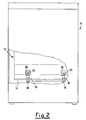
- the figures show a washing machine 11 with a rotary unit 13 connected to its base structure 12 by an elastic support device according to the invention.
- the rotary unit 13 comprises a tub 14 containing a drum 15 rotated by an underlying motor 16 via a relative transmission 17.
- the support device comprises four metal cables 18, the ends of which are locked within terminal elements 19, for example having a ring-shaped end.
- the terminal elements 19 can be inserted into U blocks or U-shaped elements 20, the sides of which comprise two mutually aligned holes 21, 22.
- the blocks 20 are fixed respectively to the tub 14 and to the base structure 12 along the side provided with the threaded hole 22, for example by welding.
- the four metal cables are fixed by inserting relative screws 23 through the hole 21, through the ring-shaped end of the terminal element 19 and into the threaded hole 22.
- the four metal cables 18 are arranged in pairs of two curved to C-shape to form semi-circumferences, the bows of which face each other.
- the diameters joining the locked ends of the metal cables are arranged so that they converge towards the centre of gravity of the rotary unit 13 and are inclined at an angle ⁇ of about 45° to the horizontal base.
- the arrangement formed by these metal cables enables the springs and stabilizer elements provided with rotary units of known type to be dispensed with.
- the characteristics of the metal cable derive from the relative slippage between its individual constituent wires and strands when it is subjected to bending, shear and torsional stresses. This is because the deformation movement is braked along the slippage region by the effect of the friction between the individual wires or strands, ie for equal frequency the amplitude of the resultant vibration is considerably reduced.
- the device of the present invention therefore achieves the effects deriving from the presence of springs and dampers in the household electrical appliances of the prior art.
- the diameter, length and number of strands and wires of the metal cables illustrated in the embodiment of the device can vary according to requirements based on the size and weight of the rotary unit 13.
- the radius of curvature depends on the cable diameter and its segment length.
- ends of the metal cable 18, individually curved and locked in any manner to define a ring are preferably aligned so that they are positioned on the same axis.
- the metal cable segments fixed to the tub 14 must be positioned as close as possible to the plane containing the centre of gravity of the system.
- the present invention therefore provides a metal cable device for supporting or suspending a rotary unit in which the cable segments operate both as springs and as dampers, as stated.
- the metal cable can generally be of stainless steel, but alternatively can be a simple steel cable protected by a plastics sheath, indicated schematically by 24 in Figure 1, to prevent degradation and/or rusting.
Landscapes
- Engineering & Computer Science (AREA)
- General Engineering & Computer Science (AREA)
- Mechanical Engineering (AREA)
- Textile Engineering (AREA)
- Aviation & Aerospace Engineering (AREA)
- Acoustics & Sound (AREA)
- Physics & Mathematics (AREA)
- Flexible Shafts (AREA)
- Vibration Prevention Devices (AREA)
- Insertion, Bundling And Securing Of Wires For Electric Apparatuses (AREA)
- Electric Cable Arrangement Between Relatively Moving Parts (AREA)
- Suspension Of Electric Lines Or Cables (AREA)
- Cable Accessories (AREA)
- Installation Of Indoor Wiring (AREA)
Claims (7)
- Elastische Antistoß- und Antivibrations-Metallkabeleinrichtung zum Halten einer Dreheinheit (13), insbesondere von einem elektrischen Haushaltsgerät, umfassend die Dreheinheit (13), freischwimmend mit Bezug auf eine Basisstruktur (12) der Einrichtung angeordnet und wenigstens ein Paar von gekrümmten Metallkabeln (18), die zwischen der Basisstruktur (12) und der Dreheinheit (13) positioniert sind, wobei die Enden des wenigstens einen Paars von Metallkabeln (18) lösbar an der Basisstruktur (12) und der Dreheinheit (13) mittels U-förmiger Elemente (20) angebracht sind, dadurch gekennzeichnet, daß die Enden des wenigstens einen Paars von Metallkabeln (18) ringförmig sind, und jedes U-förmige Element (20) zwei gegenseitig fluchtende Löcher (21, 22) umfaßt, worin jedes U-förmige Element (20) mit einem der ringförmigen Enden (19) von jedem der Kabel (18) derart in Eingriff ist, daß die beiden gegenseitig fluchtenden Löcher (21, 22) des U-förmigen Elements (20) im wesentlichen in Fluchtung mit dem Loch sind, welches von dem ringförmigen Ende (19) von jedem der Kabel (18) gebildet ist, und eine Schraubenverbindung zwischen der Basisstruktur (12) bzw. der Dreheinheit (13) mittels der Erstreckung der Schraubenverbindung durch die genannten Löcher (21, 22) und das Loch des ringförmigen Endes (19) von jedem der Kabel (18) vorgesehen ist.
- Elastische Einrichtung nach Anspruch 1, dadurch gekennzeichnet, daß das wenigstens eine Paar von Metallkabeln (18) zu einer C-Form gekrümmt ist.
- Elastische Einrichtung nach Anspruch 1, dadurch gekennzeichnet, daß jedes Metallkabel (18) des wenigstens einen Paars von Metallkabeln (18) mit seinem Bogen dem Bogen des anderen zugewandt positioniert ist.
- Elastische Einrichtung nach Anspruch 1, dadurch gekennzeichnet, daß die Durchmesser, welche die verbindbaren Enden der Metallkabel (18) verbinden, nach dem Schwerpunkt der Dreheinheit (13) zu konvergieren.
- Elastische Einrichtung nach Anspruch 1, dadurch gekennzeichnet, daß die Durchmesser, welche die verbindbaren Enden der Metallkabel (18) verbinden, um einen Winkel (β) von etwa 45° zur Horizontalen geneigt sind.
- Elastische Einrichtung nach Anspruch 1, dadurch gekennzeichnet, daß wenigstens eines der Löcher (22) der U-förmigen Elemente (20), die zwei fluchtende Löcher (21, 22) umfassen, mit Gewinde versehen ist.
- Elastische Einrichtung nach Anspruch 1, dadurch gekennzeichnet, daß jedes Metallkabel (18) in eine Kunststoffhülle (24) eingefügt ist.
Applications Claiming Priority (3)
| Application Number | Priority Date | Filing Date | Title |
|---|---|---|---|
| ITMI920787U IT226869Z2 (it) | 1992-08-20 | 1992-08-20 | Dispositivo elastico a cavo metallico ed antivibrazione per il supporto di un gruppo rotante |
| ITMI920787U | 1992-08-20 | ||
| PCT/EP1993/002138 WO1994004843A1 (en) | 1992-08-20 | 1993-08-10 | Elastic anti-impact and anti-vibration metal cable device for supporting a rotary unit |
Publications (2)
| Publication Number | Publication Date |
|---|---|
| EP0655111A1 EP0655111A1 (de) | 1995-05-31 |
| EP0655111B1 true EP0655111B1 (de) | 1996-06-26 |
Family
ID=11362743
Family Applications (1)
| Application Number | Title | Priority Date | Filing Date |
|---|---|---|---|
| EP93917779A Expired - Lifetime EP0655111B1 (de) | 1992-08-20 | 1993-08-10 | Elastische kabelstütze für stoss- und vibrationsschutz von rotierenden einheiten |
Country Status (6)
| Country | Link |
|---|---|
| EP (1) | EP0655111B1 (de) |
| AT (1) | ATE139829T1 (de) |
| DE (1) | DE69303375T2 (de) |
| ES (1) | ES2092322T3 (de) |
| IT (1) | IT226869Z2 (de) |
| WO (1) | WO1994004843A1 (de) |
Cited By (3)
| Publication number | Priority date | Publication date | Assignee | Title |
|---|---|---|---|---|
| EP1115935B1 (de) * | 1998-06-26 | 2006-06-21 | Arcelik A.S. | Waschmaschine |
| US9255399B2 (en) | 2013-12-06 | 2016-02-09 | Itt Manufacturing Enterprises Llc | Seismic isolation assembly |
| US10539204B2 (en) | 2014-09-24 | 2020-01-21 | Itt Manufacturing Enterprises Llc | Damping and support device for electrical equipments |
Families Citing this family (7)
| Publication number | Priority date | Publication date | Assignee | Title |
|---|---|---|---|---|
| RU2173803C2 (ru) * | 1999-10-25 | 2001-09-20 | Военно-морская академия им. Адмирала Флота Советского Союза Н.Г. Кузнецова | Пружинный виброизолятор с демпфирующим элементом |
| US6406011B1 (en) * | 2000-02-02 | 2002-06-18 | Enidine Incorporated | Wire rope isolator with pinned bar and method for making same |
| DE10115032A1 (de) * | 2001-03-27 | 2002-10-02 | Aeg Hausgeraete Gmbh | Schwingungsisolierende Lagerung für einen Motor oder eine motorisch angetriebene Baueinheit |
| ES2234353B1 (es) * | 2002-05-06 | 2006-10-01 | Bsh Electrodomesticos España, S.A. | Dispositivo de fijacion para la sujecion de un amortiguador de una maquina de lavar. |
| DE602004019320D1 (de) | 2003-12-23 | 2009-03-19 | Suspensiones Elasticas Del Nor | Schwingungsisolierender Dämpfer |
| EP2955262B1 (de) * | 2014-06-10 | 2017-01-25 | Imesa Spa | Waschmaschine |
| CN118408001B (zh) * | 2024-07-01 | 2024-09-24 | 成都世源频控技术股份有限公司 | 一种减振结构、制作方法及具备该减振结构的晶体振荡器 |
Family Cites Families (3)
| Publication number | Priority date | Publication date | Assignee | Title |
|---|---|---|---|---|
| US2873109A (en) * | 1956-01-23 | 1959-02-10 | Westinghouse Electric Corp | Vibration isolating mounts |
| FR1560072A (de) * | 1967-03-30 | 1969-03-14 | ||
| DE9201144U1 (de) * | 1992-01-31 | 1993-06-03 | Robert Bosch Gmbh, 7000 Stuttgart | Einrichtung zur schwingungsdämpfenden Lagerung einer Trägerplatte auf einem Gehäuseteil |
-
1992
- 1992-08-20 IT ITMI920787U patent/IT226869Z2/it active IP Right Grant
-
1993
- 1993-08-10 EP EP93917779A patent/EP0655111B1/de not_active Expired - Lifetime
- 1993-08-10 DE DE69303375T patent/DE69303375T2/de not_active Expired - Lifetime
- 1993-08-10 AT AT93917779T patent/ATE139829T1/de not_active IP Right Cessation
- 1993-08-10 WO PCT/EP1993/002138 patent/WO1994004843A1/en not_active Ceased
- 1993-08-10 ES ES93917779T patent/ES2092322T3/es not_active Expired - Lifetime
Cited By (4)
| Publication number | Priority date | Publication date | Assignee | Title |
|---|---|---|---|---|
| EP1115935B1 (de) * | 1998-06-26 | 2006-06-21 | Arcelik A.S. | Waschmaschine |
| US9255399B2 (en) | 2013-12-06 | 2016-02-09 | Itt Manufacturing Enterprises Llc | Seismic isolation assembly |
| US9809975B2 (en) | 2013-12-06 | 2017-11-07 | Itt Manufacturing Enterprises Llc | Seismic isolation assembly |
| US10539204B2 (en) | 2014-09-24 | 2020-01-21 | Itt Manufacturing Enterprises Llc | Damping and support device for electrical equipments |
Also Published As
| Publication number | Publication date |
|---|---|
| ATE139829T1 (de) | 1996-07-15 |
| DE69303375D1 (de) | 1996-08-01 |
| ES2092322T3 (es) | 1996-11-16 |
| ITMI920787U1 (it) | 1994-02-20 |
| WO1994004843A1 (en) | 1994-03-03 |
| ITMI920787V0 (it) | 1992-08-20 |
| EP0655111A1 (de) | 1995-05-31 |
| DE69303375T2 (de) | 1997-02-06 |
| IT226869Z2 (it) | 1997-07-22 |
Similar Documents
| Publication | Publication Date | Title |
|---|---|---|
| EP0655111B1 (de) | Elastische kabelstütze für stoss- und vibrationsschutz von rotierenden einheiten | |
| CA2245621C (en) | Improved isolation system for vibratory equipment | |
| US3773285A (en) | Flexible machine mounting | |
| US3711624A (en) | Cable vibrator damper with moveable additional weights | |
| US2356818A (en) | Cleaning apparatus | |
| US3432610A (en) | Vibration dampers for suspended members | |
| US2271935A (en) | Vibration damper | |
| US3539139A (en) | Appliance for linear bodies | |
| JPS59145828A (ja) | 振動式ラム | |
| CA2041693A1 (en) | Cable reinforced mounting system | |
| KR101726311B1 (ko) | 연결재의 양측에 복수의 질량체를 갖는 스톡브릿지 형태의 케이블 댐퍼 | |
| RU2483408C1 (ru) | Гаситель вибрации | |
| US4072213A (en) | Suspended cable apparatus | |
| WO2011064348A1 (en) | Laundry treating machine provided with a vibration damper device | |
| US2058174A (en) | Vibration damper | |
| EP0113035B1 (de) | Dämpfender Abstandshalter, für Bündelleiter von elektrischen Hochspannungsleitungen, mit Dämpfungszweckmässigkeit | |
| RU2249893C1 (ru) | Ограничитель гололедообразования и колебаний проводов воздушных линий электропередачи | |
| RU2180765C1 (ru) | Гаситель вибрации | |
| US3474184A (en) | Spacer damper | |
| US3777047A (en) | Spacer damper | |
| CN104753013B (zh) | 一种可调节谐振频率的线路防震锤 | |
| JPH11244571A (ja) | 改良された懸吊手段を備えた洗濯機 | |
| CA2274402A1 (en) | Damper for an overhead cable | |
| WO1996002968A1 (en) | Spacer dampers | |
| RU2852754C1 (ru) | Гаситель пляски проводов воздушной линии электропередачи |
Legal Events
| Date | Code | Title | Description |
|---|---|---|---|
| PUAI | Public reference made under article 153(3) epc to a published international application that has entered the european phase |
Free format text: ORIGINAL CODE: 0009012 |
|
| 17P | Request for examination filed |
Effective date: 19950216 |
|
| AK | Designated contracting states |
Kind code of ref document: A1 Designated state(s): AT BE CH DE DK ES FR GB IT LI NL SE |
|
| 17Q | First examination report despatched |
Effective date: 19951016 |
|
| GRAH | Despatch of communication of intention to grant a patent |
Free format text: ORIGINAL CODE: EPIDOS IGRA |
|
| GRAH | Despatch of communication of intention to grant a patent |
Free format text: ORIGINAL CODE: EPIDOS IGRA |
|
| GRAA | (expected) grant |
Free format text: ORIGINAL CODE: 0009210 |
|
| AK | Designated contracting states |
Kind code of ref document: B1 Designated state(s): AT BE CH DE DK ES FR GB IT LI NL SE |
|
| PG25 | Lapsed in a contracting state [announced via postgrant information from national office to epo] |
Ref country code: NL Free format text: LAPSE BECAUSE OF FAILURE TO SUBMIT A TRANSLATION OF THE DESCRIPTION OR TO PAY THE FEE WITHIN THE PRESCRIBED TIME-LIMIT Effective date: 19960626 Ref country code: LI Free format text: LAPSE BECAUSE OF FAILURE TO SUBMIT A TRANSLATION OF THE DESCRIPTION OR TO PAY THE FEE WITHIN THE PRESCRIBED TIME-LIMIT Effective date: 19960626 Ref country code: DK Effective date: 19960626 Ref country code: CH Free format text: LAPSE BECAUSE OF FAILURE TO SUBMIT A TRANSLATION OF THE DESCRIPTION OR TO PAY THE FEE WITHIN THE PRESCRIBED TIME-LIMIT Effective date: 19960626 Ref country code: BE Effective date: 19960626 Ref country code: AT Effective date: 19960626 |
|
| REF | Corresponds to: |
Ref document number: 139829 Country of ref document: AT Date of ref document: 19960715 Kind code of ref document: T |
|
| REF | Corresponds to: |
Ref document number: 69303375 Country of ref document: DE Date of ref document: 19960801 |
|
| ITF | It: translation for a ep patent filed | ||
| PG25 | Lapsed in a contracting state [announced via postgrant information from national office to epo] |
Ref country code: SE Effective date: 19960926 |
|
| REG | Reference to a national code |
Ref country code: ES Ref legal event code: FG2A Ref document number: 2092322 Country of ref document: ES Kind code of ref document: T3 |
|
| ITPR | It: changes in ownership of a european patent |
Owner name: CESSIONE EPO REG. 20;ELECTROLUX ZANUSSI ELETTRODOM |
|
| NLV1 | Nl: lapsed or annulled due to failure to fulfill the requirements of art. 29p and 29m of the patents act | ||
| ET | Fr: translation filed |
Free format text: CORRECTIONS |
|
| REG | Reference to a national code |
Ref country code: CH Ref legal event code: PL |
|
| RAP2 | Party data changed (patent owner data changed or rights of a patent transferred) |
Owner name: ELECTROLUX ZANUSSI ELETTRODOMESTICI S.P.A. |
|
| RIN2 | Information on inventor provided after grant (corrected) |
Free format text: CAMOSSI, CARLO |
|
| REG | Reference to a national code |
Ref country code: ES Ref legal event code: PC2A |
|
| PLBE | No opposition filed within time limit |
Free format text: ORIGINAL CODE: 0009261 |
|
| STAA | Information on the status of an ep patent application or granted ep patent |
Free format text: STATUS: NO OPPOSITION FILED WITHIN TIME LIMIT |
|
| 26N | No opposition filed | ||
| REG | Reference to a national code |
Ref country code: FR Ref legal event code: TP |
|
| REG | Reference to a national code |
Ref country code: GB Ref legal event code: IF02 |
|
| PGFP | Annual fee paid to national office [announced via postgrant information from national office to epo] |
Ref country code: ES Payment date: 20090820 Year of fee payment: 17 |
|
| PGFP | Annual fee paid to national office [announced via postgrant information from national office to epo] |
Ref country code: GB Payment date: 20090827 Year of fee payment: 17 Ref country code: DE Payment date: 20090821 Year of fee payment: 17 |
|
| PGFP | Annual fee paid to national office [announced via postgrant information from national office to epo] |
Ref country code: IT Payment date: 20090805 Year of fee payment: 17 |
|
| GBPC | Gb: european patent ceased through non-payment of renewal fee |
Effective date: 20100810 |
|
| REG | Reference to a national code |
Ref country code: FR Ref legal event code: ST Effective date: 20110502 |
|
| PG25 | Lapsed in a contracting state [announced via postgrant information from national office to epo] |
Ref country code: IT Free format text: LAPSE BECAUSE OF NON-PAYMENT OF DUE FEES Effective date: 20100810 |
|
| REG | Reference to a national code |
Ref country code: DE Ref legal event code: R119 Ref document number: 69303375 Country of ref document: DE Effective date: 20110301 |
|
| PG25 | Lapsed in a contracting state [announced via postgrant information from national office to epo] |
Ref country code: FR Free format text: LAPSE BECAUSE OF NON-PAYMENT OF DUE FEES Effective date: 20100831 Ref country code: DE Free format text: LAPSE BECAUSE OF NON-PAYMENT OF DUE FEES Effective date: 20110301 |
|
| PG25 | Lapsed in a contracting state [announced via postgrant information from national office to epo] |
Ref country code: GB Free format text: LAPSE BECAUSE OF NON-PAYMENT OF DUE FEES Effective date: 20100810 |
|
| PGFP | Annual fee paid to national office [announced via postgrant information from national office to epo] |
Ref country code: FR Payment date: 20090914 Year of fee payment: 17 |
|
| REG | Reference to a national code |
Ref country code: ES Ref legal event code: FD2A Effective date: 20111118 |
|
| PG25 | Lapsed in a contracting state [announced via postgrant information from national office to epo] |
Ref country code: ES Free format text: LAPSE BECAUSE OF NON-PAYMENT OF DUE FEES Effective date: 20100811 |