EP0655199A2 - Backofen - Google Patents
Backofen Download PDFInfo
- Publication number
- EP0655199A2 EP0655199A2 EP94500198A EP94500198A EP0655199A2 EP 0655199 A2 EP0655199 A2 EP 0655199A2 EP 94500198 A EP94500198 A EP 94500198A EP 94500198 A EP94500198 A EP 94500198A EP 0655199 A2 EP0655199 A2 EP 0655199A2
- Authority
- EP
- European Patent Office
- Prior art keywords
- oven
- bridge
- oven according
- hot air
- heated chamber
- Prior art date
- Legal status (The legal status is an assumption and is not a legal conclusion. Google has not performed a legal analysis and makes no representation as to the accuracy of the status listed.)
- Withdrawn
Links
- 238000010438 heat treatment Methods 0.000 claims abstract description 14
- 238000010411 cooking Methods 0.000 claims abstract description 12
- 235000013305 food Nutrition 0.000 claims abstract description 3
- 238000006073 displacement reaction Methods 0.000 claims description 6
- 239000012530 fluid Substances 0.000 abstract description 9
- 230000008878 coupling Effects 0.000 description 3
- 238000010168 coupling process Methods 0.000 description 3
- 238000005859 coupling reaction Methods 0.000 description 3
- 230000007246 mechanism Effects 0.000 description 3
- 230000015572 biosynthetic process Effects 0.000 description 2
- 238000000605 extraction Methods 0.000 description 2
- 230000002093 peripheral effect Effects 0.000 description 2
- 230000003068 static effect Effects 0.000 description 2
- 238000004519 manufacturing process Methods 0.000 description 1
- 238000000034 method Methods 0.000 description 1
- 238000005192 partition Methods 0.000 description 1
- 238000009827 uniform distribution Methods 0.000 description 1
Images

Classifications
-
- A—HUMAN NECESSITIES
- A21—BAKING; EDIBLE DOUGHS
- A21B—BAKERS' OVENS; MACHINES OR EQUIPMENT FOR BAKING
- A21B1/00—Bakers' ovens
- A21B1/02—Bakers' ovens characterised by the heating arrangements
- A21B1/24—Ovens heated by media flowing therethrough
- A21B1/26—Ovens heated by media flowing therethrough by hot air
Definitions
- the present specification concerns, as its title indicates, an improved oven of the type used to cook products, preferably food and which incorporates heating means and turbines which project the hot air towards the interior of the oven.
- the ovens which are currently known incorporate a turbine which pushes the hot air by heating means and launches it towards the interior zone of the furnace through a plurality of orifices or grooves arranged in the partitions of the latter, so that we obtain the heating of this interior area of the oven where there is a tray-holder carriage which serves as a support for the product to be cooked.
- This type of oven in order to obtain a uniform distribution of heat inside the heated chamber, in the sides which delimit it have a very high number of orifices for the exit of hot air, because otherwise the heat would fall on determined points of the product, so that the cooking thereof would not be uniform; moreover, this high number of outlets is arranged both in rotary ovens, in which the carriage turns on a central axis, and in static ovens in which the tray-carrying carriage does not move during the cooking process of the product. .
- the improved object of the present invention has been designed, which has the particularity of presenting a hollow bridge inside the heated chamber, with a reduced number of orifices arranged vertically on the inner flanks of the latter. ci, this hollow bridge being mounted on parallel guides on which it can move longitudinally to describe alternative movements with a stroke of length equal to that existing between two consecutive hot air outlet orifices.
- This hollow bridge internally defines dimensions which allow the positioning in its interior of at least one trolley carrying trays with the product to be cooked.
- the hollow bridge has a hot air inlet orifice on which is coupled a duct inside which circulates the hot fluid collected from the heating means and projected by a turbine; the coupling between the hollow bridge and the hot fluid circulation duct is sliding, so that the bridge can move, describing the previously mentioned alternative movements, maintaining the coupling with the fixed hot air circulation duct.
- the reciprocating movements of the bridge on the guides be carried out by means of a movement transmitting mechanism actuated by a motor element, which allows that when the bridge describes these reciprocating movements, the outputs move from an original position up to 'to obtain the position previously occupied by the consecutive outlet in the running direction, the hot fluid performing successive scans on the product, obtaining uniform cooking thereof with a reduced number of outlets.
- this oven has the advantage that its total length can be increased as much as desired, by incorporating inside the heated chamber several hollow bridges, with their corresponding heating means, turbines and transmitting mechanisms. movement, all the bridges moving simultaneously to form a cooking tunnel inside which one can have aligned several tray trolleys with the product to be cooked.
- the oven of the invention incorporates a heated chamber (1), where the cooking of the product is carried out, the heating thereof being effected by the introduction of hot air; this oven also incorporates an annex compartment (2) where are housed heating means (3) and a turbine (4) responsible for projecting hot air into the interior of the chamber (1).
- the turbine (4) and the bridge (5) are linked together by a fixed duct (7) which is introduced inside the heated chamber (1) and the end of which couples with the possibility of displacement on the exterior wall of the bridge (5); to achieve this coupling it is expected that the conduit (7) ends with the mouth which is introduced inside the bridge (5) in a plane peripheral frame, and that the bulkhead of the bridge (5) defines an orifice of dimensions greater than the section of the conduit (7) and less than the surface defined by this peripheral frame disposed in the conduit (7); in this way, the bridge (5) will remain connected to the conduit (7) regardless of the position of the path it occupies, allowing the entry of the hot fluid projected by the turbine.
- the bridge (5) is supported with the possibility of displacement on lower guides (8) with the possibility of being able to carry out reciprocating movements whose course coincides with the distance which separates two consecutive exits (6).
- the bridge (5) can move over the guides (8), provision has been made for the latter to be actuated by a motor element (9) by means of a movement-transmitting mechanism, which in this embodiment is composed by a rack (10) integral with the bridge (5), and on which acts a drive pinion (11) actuated by the drive element (9).
- a movement-transmitting mechanism which in this embodiment is composed by a rack (10) integral with the bridge (5), and on which acts a drive pinion (11) actuated by the drive element (9).
- the bridge (5) defines adequate dimensions for allow the housing in its interior of at least one tray-carrying trolley (12) intended to support the product to be cooked inside the heated chamber (1).
- the heated chamber (1) and the annex compartment (2) are separated by a humidifying chamber (13), below which is an orifice (14) which allows the passage of the hot fluid from the heated chamber (1) to the annex compartment (2), so that the hot fluid contained in the heated chamber (1) is absorbed by the turbine (4), passing through the orifice (14) and the heating means (3), to be projected again from the interior of the duct (7) towards the bridge (5) emerging from the orifices (6) defined in the bridge (5); in this way, a continuous circulation of fluid is formed, thus obtaining a high efficiency of the furnace.
- the heated chamber (1) has two opposite inlets (15) and (16) which can be open to the outside, closed by fixed transparent plates (17) or removable (18).
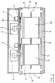
- this oven allows the heated chamber (1) to define a length as long as desired, with the possibility of incorporating several aligned bridges, as shown in FIG. 2, to carry out the simultaneous cooking of the product contained in several trolleys tray holder (12), because once these have been inserted inside the oven, they remain static, the hollow bridges (5) moving simultaneously.
- the oven comprises drive means preferably formed by a chain (19) with means fixing the carriage.
- each of the bridges (5) will comprise the corresponding cooking means (3), the turbines (4) and the displacement means.
Landscapes
- Life Sciences & Earth Sciences (AREA)
- Engineering & Computer Science (AREA)
- Food Science & Technology (AREA)
- Baking, Grill, Roasting (AREA)
Applications Claiming Priority (2)
| Application Number | Priority Date | Filing Date | Title |
|---|---|---|---|
| ES09302499A ES2076874B1 (es) | 1993-11-26 | 1993-11-26 | Horno perfeccionado. |
| ES9302499 | 1993-11-26 |
Publications (2)
| Publication Number | Publication Date |
|---|---|
| EP0655199A2 true EP0655199A2 (de) | 1995-05-31 |
| EP0655199A3 EP0655199A3 (de) | 1998-07-15 |
Family
ID=8283771
Family Applications (1)
| Application Number | Title | Priority Date | Filing Date |
|---|---|---|---|
| EP94500198A Withdrawn EP0655199A3 (de) | 1993-11-26 | 1994-11-25 | Backofen |
Country Status (3)
| Country | Link |
|---|---|
| US (1) | US5529052A (de) |
| EP (1) | EP0655199A3 (de) |
| ES (1) | ES2076874B1 (de) |
Families Citing this family (7)
| Publication number | Priority date | Publication date | Assignee | Title |
|---|---|---|---|---|
| CN100451510C (zh) * | 2006-07-05 | 2009-01-14 | 开封市四达农产品设备有限公司 | 气流喷射式物料烘干机 |
| JP4457166B2 (ja) * | 2008-07-30 | 2010-04-28 | シャープ株式会社 | 加熱調理器 |
| CA2911721C (en) * | 2014-05-14 | 2019-01-22 | Samuel Ralph BLUE | Smoker oven with improved air flow |
| US10415836B2 (en) * | 2015-02-06 | 2019-09-17 | Michael James McIntyre | Cooking apparatus and air delivery and circulation device therefore |
| US11627743B2 (en) * | 2020-01-09 | 2023-04-18 | Haier Us Appliance Solutions, Inc. | Rack assembly for an indoor smoker |
| CN113017446B (zh) * | 2021-04-15 | 2022-02-18 | 安徽省小岗盼盼食品有限公司 | 一种实现均匀加热的面包烘烤设备 |
| CN117256635A (zh) * | 2023-10-07 | 2023-12-22 | 吉林省艾斯克机电有限责任公司 | 一种框架运行热风蒸烤机 |
Family Cites Families (10)
| Publication number | Priority date | Publication date | Assignee | Title |
|---|---|---|---|---|
| CH347768A (de) * | 1957-02-20 | 1960-07-15 | Zech Jean | Trocknungsanlage für stapelbare Güter |
| US3375592A (en) * | 1965-08-30 | 1968-04-02 | Heinicke Instr Co | Traveling dryer for vehicle washing apparatus |
| GB1183202A (en) * | 1966-08-11 | 1970-03-04 | Everson & Sons Ltd G R | Improvements in or relating to Ovens |
| SU521441A1 (ru) * | 1973-07-02 | 1976-07-15 | Вентил ционна установка дл сушки пиломатериалов в штабел х | |
| US4242807A (en) * | 1978-08-11 | 1981-01-06 | Hunter Engineering Co., Inc. | Paint line flotation oven |
| FR2469124A1 (fr) * | 1979-11-13 | 1981-05-22 | Voegtlin Rene | Four a recyclage d'air chaud pour la cuisson des produits de boulangerie, viennoiserie, patisserie et similaire |
| FR2534452A1 (fr) * | 1982-10-15 | 1984-04-20 | Voegtlin Rene | Four a recyclage d'air chaud pour produits cuits en pate |
| ES1000195Y (es) * | 1986-09-11 | 1988-06-16 | Hornos Instalaciones Panaderias Laboral, S.A. (Hipsal) | Horno de pisos |
| SE9100335L (sv) * | 1991-02-04 | 1992-08-05 | Revent Int Ab | Konvektionsugn |
| US5129384A (en) * | 1991-09-03 | 1992-07-14 | Reed Oven Company | Bakery oven with enhanced air flow |
-
1993
- 1993-11-26 ES ES09302499A patent/ES2076874B1/es not_active Expired - Fee Related
-
1994
- 1994-11-25 EP EP94500198A patent/EP0655199A3/de not_active Withdrawn
- 1994-11-28 US US08/345,311 patent/US5529052A/en not_active Expired - Fee Related
Also Published As
| Publication number | Publication date |
|---|---|
| EP0655199A3 (de) | 1998-07-15 |
| ES2076874A2 (es) | 1995-11-01 |
| ES2076874R (de) | 1998-03-01 |
| ES2076874B1 (es) | 1998-11-01 |
| US5529052A (en) | 1996-06-25 |
Similar Documents
| Publication | Publication Date | Title |
|---|---|---|
| US20180303285A1 (en) | Air fryer | |
| EP0655199A2 (de) | Backofen | |
| US20070125319A1 (en) | Convection oven with laminar airflow and method | |
| FR2533679A1 (fr) | Armoire chauffante | |
| EP0289435B1 (de) | Vakuumsofen mit Gaskühlung für Wärmebehandlung | |
| EP0611251A1 (de) | Kühlungsverfahren und -vorrichtung für ein Extrudergehäuse | |
| IT9012541A1 (it) | Dispositivo ad uso domestico od industriale, per omogeneizzare, miscelare, emulsionare, dei prodotti liquidi in genere, in particolare latte, caffe' e panna, allo scopo di conferire a questi prodotti un aspetto cremoso | |
| WO2000034160A1 (en) | A flexible conveyor belt and a climate chamber comprising a belt of that kind | |
| US4156383A (en) | Dual-rotating mechanism for ovens | |
| CN110211291A (zh) | 一种结构精简的自动售卖机 | |
| US1158175A (en) | Solar cooker. | |
| US5125233A (en) | Energy conversion apparatus | |
| US696326A (en) | Solar heating apparatus. | |
| JP7740991B2 (ja) | コーヒー豆を焙煎するためのシステム及び方法 | |
| IT9021030A1 (it) | Dispositivo per la pulizia mediante pirolisi della camera di cottura di un forno atto alla preparazione degli alimenti | |
| ITBO20070579A1 (it) | Forno a tunnel per prodotti alimentari, in particolare per prodotti da forno, quali pizze, focacce e simili. | |
| WO1995009533A1 (fr) | Four a air a convection | |
| KR20170101461A (ko) | 열풍 김구이기 | |
| KR102659866B1 (ko) | 꼬치 구이장치 | |
| FR2535036A1 (fr) | Four a recyclage d'air chaud a chariot fixe | |
| KR200260864Y1 (ko) | 전기 찜기의 물방울 낙하 방지 장치 | |
| KR101844182B1 (ko) | 고기구이장치를 갖는 테이블 | |
| CN221505484U (zh) | 一种荧光增白剂晶体脱水装置 | |
| TWM594424U (zh) | 自動化鳥蛋破蛋及蛋殼分離之裝置 | |
| FR2840058A1 (fr) | Four mixte a haut rendement pour aliments, du type avec modalite de cuisson a convection et/ou a vapeur |
Legal Events
| Date | Code | Title | Description |
|---|---|---|---|
| PUAI | Public reference made under article 153(3) epc to a published international application that has entered the european phase |
Free format text: ORIGINAL CODE: 0009012 |
|
| AK | Designated contracting states |
Kind code of ref document: A2 Designated state(s): AT DE FR GB IT PT |
|
| PUAL | Search report despatched |
Free format text: ORIGINAL CODE: 0009013 |
|
| AK | Designated contracting states |
Kind code of ref document: A3 Designated state(s): AT DE FR GB IT PT |
|
| STAA | Information on the status of an ep patent application or granted ep patent |
Free format text: STATUS: THE APPLICATION IS DEEMED TO BE WITHDRAWN |
|
| 18D | Application deemed to be withdrawn |
Effective date: 19990116 |