EP0655332A1 - Cylindre de plaque - Google Patents
Cylindre de plaque Download PDFInfo
- Publication number
- EP0655332A1 EP0655332A1 EP94118470A EP94118470A EP0655332A1 EP 0655332 A1 EP0655332 A1 EP 0655332A1 EP 94118470 A EP94118470 A EP 94118470A EP 94118470 A EP94118470 A EP 94118470A EP 0655332 A1 EP0655332 A1 EP 0655332A1
- Authority
- EP
- European Patent Office
- Prior art keywords
- printing plate
- forme cylinder
- slot
- compressed air
- pressure plate
- Prior art date
- Legal status (The legal status is an assumption and is not a legal conclusion. Google has not performed a legal analysis and makes no representation as to the accuracy of the status listed.)
- Granted
Links
- 238000007639 printing Methods 0.000 claims abstract description 30
- 230000037431 insertion Effects 0.000 claims description 12
- 238000003780 insertion Methods 0.000 claims description 12
- 239000000725 suspension Substances 0.000 abstract 2
- 230000001154 acute effect Effects 0.000 description 3
- 238000007645 offset printing Methods 0.000 description 1
Images
Classifications
-
- B—PERFORMING OPERATIONS; TRANSPORTING
- B41—PRINTING; LINING MACHINES; TYPEWRITERS; STAMPS
- B41F—PRINTING MACHINES OR PRESSES
- B41F27/00—Devices for attaching printing elements or formes to supports
- B41F27/12—Devices for attaching printing elements or formes to supports for attaching flexible printing formes
- B41F27/1293—Devices for filling up the cylinder gap; Devices for removing the filler
Definitions
- the invention relates to a forme cylinder with slot-shaped pressure plate insertion according to the preamble of claim 1.
- a supply device for compressed air on a rotatable cylinder of a printing press via a cylinder journal has become known.
- Compressed air is first supplied to one or more radially arranged bores, which are connected to one or more axially extending bores, via a supply which is fixed to the frame and has an outlet which can be lowered temporarily to the surface or in the vicinity of the cylinder journal.
- the axially extending bores are connected to radially extending bores which open into plug-in means or openings for the compressed air outlet.
- Forme cylinders for offset roll rotary printing presses with slot-shaped printing plate insertion have been known for a long time.
- the beginning of the printing plate is bent with an acute and the end of the printing plate with an obtuse opening angle.
- the end of the pressure plate with the acute opening angle is first seen in an acute-angled hook-in edge, seen in cross section hooked in, whereby the length of the hooking edge corresponds at least to the pressure plate width.
- the hooking edge formed from a hooking radius with an inclined contact surface for the beginning of the printing plate, forms, together with a contact surface for the printing plate end folding, which is parallel to it, and a base surface adjoining it, the slot-shaped printing plate end entry.
- the distance between the opposing contact surfaces is slightly larger than twice the printing plate thickness.
- This very narrow slot for receiving the two printing plate ends and the full seating of the printing plate on the circumference of the forme cylinder means that the printing plate end bend cannot be pulled out of the slot so easily in order to change the printing plate. That's why you use suction cups that you put on the area around the pressure plate end on the pressure plate and then pull the end out of the slot with more or less damage.
- the invention has for its object to provide a device on a forme cylinder of a rotary printing press, with which a folded end of a printing plate without tools is easily lifted from an insertion slot for receiving printing plate bends at least as far in the slot that the printing plate end convenient by an operator or Automat can be pulled out of the slot and thus the affected end of the pressure plate can be lifted from the cylinder circumference.
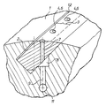
- a forme cylinder 1 of a rotary printing press On a forme cylinder 1 of a rotary printing press is one, two bent ends having printing plate z. B. placed an offset printing plate.
- the fold for the beginning of the printing plate has an acute angle
- the fold for the end of the printing plate has an obtuse angle Beta.
- Both ends come to rest in an insertion gap 2 in the forme cylinder 1 when the printing plate is placed on top.
- Such an insertion gap 2 is well known and has been described in detail in the introduction to the description, so that a repetition is omitted for reasons of simplification.
- At least the pressure plate end with the bend with an obtuse-angled opening angle Beta - hereinafter referred to as "obtuse-angled bend" - is pressed into an insertion gap 2 and holds there until the pressure plate is to be replaced.
- a number of lifting devices 4 are provided for lifting the pressure plate end in the area 3 before the bend of the pressure plate end. They act out of the jacket and act on an underside of the printing plate in such a way that the end of the printing plate is raised in front of its folding line and thus pulls the end of the printing plate out of the insertion gap at least until this end can be easily detached from the forme cylinder 1.
- This lifting device 4 can consist of various means. So z. B. a lifting and lowering bar can be provided. However, a plurality of nozzles 6 can also be provided in a particularly advantageous manner for the discharge of compressed air.
- the controlled compressed air occurs e.g. B. from all the nozzles 6 at the same time and lifts the pressure plate end in the vicinity parallel to the folding line of the folded pressure plate end to the extent that at least the side edges can then be gripped.
- the end of the pressure plate is lifted up so far that the bend of the end of the pressure plate has completely left the insertion gap 2.
- the nozzles 6, which end with the lateral surface of the forme cylinder 1, ie do not protrude beyond them, are fed with compressed air via first radial bores 7.
- the bores 7 begin in an axially extending storage chamber 8 for the compressed air, which by means of several second radiler Bores 9 is connected to an axial bore 11.
- This axial bore 11 is connected to a radial bore, not shown, in a shaft journal.
- the clocked supply of compressed air via z. B. a device according to DE 42 03 550 A1 from a compressed air source.
Landscapes
- Supply, Installation And Extraction Of Printed Sheets Or Plates (AREA)
Applications Claiming Priority (2)
| Application Number | Priority Date | Filing Date | Title |
|---|---|---|---|
| DE4340651 | 1993-11-30 | ||
| DE4340651A DE4340651C1 (de) | 1993-11-30 | 1993-11-30 | Formzylinder mit schlitzförmiger Druckplatteneinführung |
Publications (2)
| Publication Number | Publication Date |
|---|---|
| EP0655332A1 true EP0655332A1 (fr) | 1995-05-31 |
| EP0655332B1 EP0655332B1 (fr) | 1998-10-14 |
Family
ID=6503718
Family Applications (1)
| Application Number | Title | Priority Date | Filing Date |
|---|---|---|---|
| EP94118470A Expired - Lifetime EP0655332B1 (fr) | 1993-11-30 | 1994-11-24 | Cylindre de plaque |
Country Status (3)
| Country | Link |
|---|---|
| EP (1) | EP0655332B1 (fr) |
| JP (1) | JPH07195672A (fr) |
| DE (2) | DE4340651C1 (fr) |
Families Citing this family (4)
| Publication number | Priority date | Publication date | Assignee | Title |
|---|---|---|---|---|
| JP2952752B2 (ja) * | 1995-11-17 | 1999-09-27 | 株式会社東京機械製作所 | 刷版の版胴への固定および版胴からの解離装置 |
| DE19758453C2 (de) * | 1996-01-19 | 2002-09-19 | Roland Man Druckmasch | Vorrichtung zum Befestigen einer Bespannung auf einem Druckwerkzylinder |
| DE29600845U1 (de) * | 1996-01-19 | 1996-03-07 | MAN Roland Druckmaschinen AG, 63075 Offenbach | Vorrichtung zum Befestigen einer Bespannung auf einem Druckwerkzylinder |
| DE19815935A1 (de) * | 1998-04-09 | 1999-10-14 | Roland Man Druckmasch | Druckzylinder |
Citations (2)
| Publication number | Priority date | Publication date | Assignee | Title |
|---|---|---|---|---|
| EP0215645A2 (fr) * | 1985-09-17 | 1987-03-25 | The Ward Machinery Company | Montage de matrices et de plaques d'impression |
| DE4203550A1 (de) * | 1992-02-07 | 1993-08-12 | Koenig & Bauer Ag | Zufuehreinrichtung fuer druckbeaufschlagbare medien auf rotierbare koerper, vorzugsweise zylinder in druckmaschinen |
Family Cites Families (4)
| Publication number | Priority date | Publication date | Assignee | Title |
|---|---|---|---|---|
| CH518176A (de) * | 1969-11-18 | 1972-01-31 | Linotype Machinery Ltd | Zylinder für Rotationsdruckmaschine |
| DD290623B3 (de) * | 1989-12-22 | 1992-09-03 | Erwin Dimmel | Vorrichtung zum befestigen einer biegsamen druckplatte |
| DE4132805C2 (de) * | 1991-10-02 | 1995-05-04 | Koenig & Bauer Ag | Seitenregister-Einstellvorrichtung für Druckplatten |
| DE4303381A1 (de) * | 1993-02-05 | 1994-12-01 | Roland Man Druckmasch | Plattenzylinder mit einer Einrichtung zum Anheben einer Druckplatte |
-
1993
- 1993-11-30 DE DE4340651A patent/DE4340651C1/de not_active Expired - Fee Related
-
1994
- 1994-11-21 JP JP6286910A patent/JPH07195672A/ja active Pending
- 1994-11-24 DE DE59407087T patent/DE59407087D1/de not_active Expired - Fee Related
- 1994-11-24 EP EP94118470A patent/EP0655332B1/fr not_active Expired - Lifetime
Patent Citations (2)
| Publication number | Priority date | Publication date | Assignee | Title |
|---|---|---|---|---|
| EP0215645A2 (fr) * | 1985-09-17 | 1987-03-25 | The Ward Machinery Company | Montage de matrices et de plaques d'impression |
| DE4203550A1 (de) * | 1992-02-07 | 1993-08-12 | Koenig & Bauer Ag | Zufuehreinrichtung fuer druckbeaufschlagbare medien auf rotierbare koerper, vorzugsweise zylinder in druckmaschinen |
Also Published As
| Publication number | Publication date |
|---|---|
| DE4340651C1 (de) | 1995-03-09 |
| DE59407087D1 (de) | 1998-11-19 |
| EP0655332B1 (fr) | 1998-10-14 |
| JPH07195672A (ja) | 1995-08-01 |
Similar Documents
| Publication | Publication Date | Title |
|---|---|---|
| EP0453910B1 (fr) | Chambre de racle | |
| EP0549936A1 (fr) | Cylindre de transfert avec manchon échangeable, supporté entre deux parois latérales d'un élément d'impression | |
| EP1172573A2 (fr) | Element de fixation pour insertion à force dans une tole de telle façon qu'il ne puisse ni faire sortir, ni tourner | |
| EP1214158B1 (fr) | Dispositif pour installer et retirer un palier d'un cylindre d'appui | |
| CH649252A5 (de) | Zylinder fuer druckmaschinen. | |
| EP0446668B1 (fr) | Dispositif de nettoyage pour une machine d'impression | |
| DE2702007A1 (de) | Presse mit zwei druckwalzen | |
| DE4308712B4 (de) | Druckmaschine | |
| DE19617744A1 (de) | Einrichtung zum Wechseln von Druckformen an Druckwerken von Druckmaschinen | |
| CH695765A5 (de) | Neun-Zylinder-Satellitendruckeinheit. | |
| DE4340651C1 (de) | Formzylinder mit schlitzförmiger Druckplatteneinführung | |
| EP1151860A1 (fr) | Machine pour imprimer des feuilles | |
| DE19642141C1 (de) | Vorrichtung zum Lösen von Platten | |
| DE69205959T2 (de) | Verfahren zum Formen von Blech unter hydraulischem Druck. | |
| DE9320691U1 (de) | Formzylinder | |
| EP1603750B1 (fr) | Groupe d'impression d'une unite d'impression possedant au moins deux groupes d'impression situes verticalement l'un au-dessus de l'autre dans une presse, et unite d'impression | |
| DE4213659C2 (de) | Kurzfarbwerk für eine Rotationsdruckmaschine | |
| DE4401201A1 (de) | Einrichtung zum Festhalten eines bogenförmigen Trägers | |
| EP0697286A1 (fr) | Plaque flexible ayant des bords pliés pour le montage sur un cylindre d'une machine d'impression | |
| EP0421138B1 (fr) | Dispositif de recouvrement pour tissu pour imprimer au pochoir | |
| DE10024087C2 (de) | Vorrichtung zum Befestigen einer Druckplatte auf einem Zylinder einer Rotationsdruckmaschine | |
| EP0531741A1 (fr) | Dispositif pour fixer le bord avant d'un cliché dans une machine à imprimer | |
| DE102004055704B4 (de) | Gummitücher für einen Gummituchzylinder sowie ein Gummituchzylinder einer Rotationsdruckmaschine | |
| DE3404623C2 (fr) | ||
| DE29508175U1 (de) | Schalenartiger Tragkörper |
Legal Events
| Date | Code | Title | Description |
|---|---|---|---|
| PUAI | Public reference made under article 153(3) epc to a published international application that has entered the european phase |
Free format text: ORIGINAL CODE: 0009012 |
|
| AK | Designated contracting states |
Kind code of ref document: A1 Designated state(s): CH DE FR GB IT LI SE |
|
| RAP1 | Party data changed (applicant data changed or rights of an application transferred) |
Owner name: KOENIG & BAUER-ALBERT AKTIENGESELLSCHAFT |
|
| 17P | Request for examination filed |
Effective date: 19951117 |
|
| 17Q | First examination report despatched |
Effective date: 19970310 |
|
| GRAG | Despatch of communication of intention to grant |
Free format text: ORIGINAL CODE: EPIDOS AGRA |
|
| GRAG | Despatch of communication of intention to grant |
Free format text: ORIGINAL CODE: EPIDOS AGRA |
|
| GRAH | Despatch of communication of intention to grant a patent |
Free format text: ORIGINAL CODE: EPIDOS IGRA |
|
| GRAH | Despatch of communication of intention to grant a patent |
Free format text: ORIGINAL CODE: EPIDOS IGRA |
|
| GRAA | (expected) grant |
Free format text: ORIGINAL CODE: 0009210 |
|
| AK | Designated contracting states |
Kind code of ref document: B1 Designated state(s): CH DE FR GB IT LI SE |
|
| REG | Reference to a national code |
Ref country code: CH Ref legal event code: EP |
|
| REF | Corresponds to: |
Ref document number: 59407087 Country of ref document: DE Date of ref document: 19981119 |
|
| ET | Fr: translation filed | ||
| RAP2 | Party data changed (patent owner data changed or rights of a patent transferred) |
Owner name: KOENIG & BAUER AKTIENGESELLSCHAFT |
|
| ITF | It: translation for a ep patent filed | ||
| GBT | Gb: translation of ep patent filed (gb section 77(6)(a)/1977) |
Effective date: 19990118 |
|
| PLBE | No opposition filed within time limit |
Free format text: ORIGINAL CODE: 0009261 |
|
| STAA | Information on the status of an ep patent application or granted ep patent |
Free format text: STATUS: NO OPPOSITION FILED WITHIN TIME LIMIT |
|
| 26N | No opposition filed | ||
| REG | Reference to a national code |
Ref country code: GB Ref legal event code: IF02 |
|
| PGFP | Annual fee paid to national office [announced via postgrant information from national office to epo] |
Ref country code: GB Payment date: 20041025 Year of fee payment: 11 |
|
| PGFP | Annual fee paid to national office [announced via postgrant information from national office to epo] |
Ref country code: FR Payment date: 20041118 Year of fee payment: 11 |
|
| PGFP | Annual fee paid to national office [announced via postgrant information from national office to epo] |
Ref country code: SE Payment date: 20041119 Year of fee payment: 11 |
|
| PGFP | Annual fee paid to national office [announced via postgrant information from national office to epo] |
Ref country code: CH Payment date: 20041124 Year of fee payment: 11 |
|
| PG25 | Lapsed in a contracting state [announced via postgrant information from national office to epo] |
Ref country code: IT Free format text: LAPSE BECAUSE OF NON-PAYMENT OF DUE FEES;WARNING: LAPSES OF ITALIAN PATENTS WITH EFFECTIVE DATE BEFORE 2007 MAY HAVE OCCURRED AT ANY TIME BEFORE 2007. THE CORRECT EFFECTIVE DATE MAY BE DIFFERENT FROM THE ONE RECORDED. Effective date: 20051124 Ref country code: GB Free format text: LAPSE BECAUSE OF NON-PAYMENT OF DUE FEES Effective date: 20051124 |
|
| PG25 | Lapsed in a contracting state [announced via postgrant information from national office to epo] |
Ref country code: SE Free format text: LAPSE BECAUSE OF NON-PAYMENT OF DUE FEES Effective date: 20051125 |
|
| PG25 | Lapsed in a contracting state [announced via postgrant information from national office to epo] |
Ref country code: LI Free format text: LAPSE BECAUSE OF NON-PAYMENT OF DUE FEES Effective date: 20051130 Ref country code: CH Free format text: LAPSE BECAUSE OF NON-PAYMENT OF DUE FEES Effective date: 20051130 |
|
| REG | Reference to a national code |
Ref country code: CH Ref legal event code: PL |
|
| EUG | Se: european patent has lapsed | ||
| GBPC | Gb: european patent ceased through non-payment of renewal fee |
Effective date: 20051124 |
|
| PG25 | Lapsed in a contracting state [announced via postgrant information from national office to epo] |
Ref country code: FR Free format text: LAPSE BECAUSE OF NON-PAYMENT OF DUE FEES Effective date: 20060731 |
|
| REG | Reference to a national code |
Ref country code: FR Ref legal event code: ST Effective date: 20060731 |
|
| PGFP | Annual fee paid to national office [announced via postgrant information from national office to epo] |
Ref country code: DE Payment date: 20081212 Year of fee payment: 15 |
|
| PG25 | Lapsed in a contracting state [announced via postgrant information from national office to epo] |
Ref country code: DE Free format text: LAPSE BECAUSE OF NON-PAYMENT OF DUE FEES Effective date: 20100601 |