EP0655350A1 - Instrument pour écrire, en particulier un stylographe - Google Patents
Instrument pour écrire, en particulier un stylographe Download PDFInfo
- Publication number
- EP0655350A1 EP0655350A1 EP94117637A EP94117637A EP0655350A1 EP 0655350 A1 EP0655350 A1 EP 0655350A1 EP 94117637 A EP94117637 A EP 94117637A EP 94117637 A EP94117637 A EP 94117637A EP 0655350 A1 EP0655350 A1 EP 0655350A1
- Authority
- EP
- European Patent Office
- Prior art keywords
- valve
- refill
- writing
- closed
- implement according
- Prior art date
- Legal status (The legal status is an assumption and is not a legal conclusion. Google has not performed a legal analysis and makes no representation as to the accuracy of the status listed.)
- Granted
Links
Images
Classifications
-
- B—PERFORMING OPERATIONS; TRANSPORTING
- B43—WRITING OR DRAWING IMPLEMENTS; BUREAU ACCESSORIES
- B43K—IMPLEMENTS FOR WRITING OR DRAWING
- B43K5/00—Pens with ink reservoirs in holders, e.g. fountain-pens
- B43K5/02—Ink reservoirs
- B43K5/06—Ink reservoirs with movable pistons for withdrawing ink from an ink-receptacle
- B43K5/08—Ink reservoirs with movable pistons for withdrawing ink from an ink-receptacle with ink-supplying valves
-
- B—PERFORMING OPERATIONS; TRANSPORTING
- B05—SPRAYING OR ATOMISING IN GENERAL; APPLYING FLUENT MATERIALS TO SURFACES, IN GENERAL
- B05B—SPRAYING APPARATUS; ATOMISING APPARATUS; NOZZLES
- B05B11/00—Single-unit hand-held apparatus in which flow of contents is produced by the muscular force of the operator at the moment of use
- B05B11/0005—Components or details
- B05B11/0035—Pen-like sprayers
-
- B—PERFORMING OPERATIONS; TRANSPORTING
- B43—WRITING OR DRAWING IMPLEMENTS; BUREAU ACCESSORIES
- B43K—IMPLEMENTS FOR WRITING OR DRAWING
- B43K11/00—Filling devices
-
- B—PERFORMING OPERATIONS; TRANSPORTING
- B43—WRITING OR DRAWING IMPLEMENTS; BUREAU ACCESSORIES
- B43K—IMPLEMENTS FOR WRITING OR DRAWING
- B43K5/00—Pens with ink reservoirs in holders, e.g. fountain-pens
- B43K5/18—Arrangements for feeding the ink to the nibs
- B43K5/1818—Mechanical feeding means, e.g. valves; Pumps
- B43K5/1827—Valves
- B43K5/1836—Valves automatically closing
- B43K5/1863—Valves automatically closing opened by actuation of the rear-side of the pen
-
- B—PERFORMING OPERATIONS; TRANSPORTING
- B43—WRITING OR DRAWING IMPLEMENTS; BUREAU ACCESSORIES
- B43L—ARTICLES FOR WRITING OR DRAWING UPON; WRITING OR DRAWING AIDS; ACCESSORIES FOR WRITING OR DRAWING
- B43L25/00—Ink receptacles
- B43L25/02—Ink receptacles with separate dipping-cups
- B43L25/04—Ink receptacles with separate dipping-cups supplied by pressure arrangements
Definitions
- the invention relates to a writing instrument, in particular a fountain pen, with a storage space which can be filled with ink or another writing fluid and which is connected via a connecting channel to a flow regulator and a writing tip and which can be refilled from a reserve space, which is closed by opening one in a basic position Refill valve can be connected to the storage room.
- the reserve space is arranged above the storage space in relation to normal writing posture.
- the closure element of the refill valve is connected to a plunger which is led out of the reserve space at the end opposite the tip of the application, such that the closure element can first be moved into an open position and then again into a closed position by depressing the plunger end.
- only the volume of the storage space is effective in the closed position of the refill valve.
- the storage room can therefore be designed so that the largest possible amount of enclosed air is safely controlled by the compensation capacity of the capillary system at the tip of the order, so that there can be no uneven ink flow and an unclean typeface.
- the storage space is empty, the storage space is refilled with ink from the reserve space by opening the refill valve.
- the known writing instrument has the disadvantage that it cannot be refilled with ink can and must therefore be discarded when the ink in the storage room and the spare room is used up.
- a refillable writing instrument is known from US Pat. No. 2,646,777, in which the storage space is provided at the end opposite the writing spring with a piston pump which can be actuated by a suction pipe protruding from the storage space.
- the suction tube is immersed in an ink container and the piston pump is actuated by moving the writing instrument up and down.
- the disadvantage here is that when refilling due to the pressure in the ink regulator increasing in the storage space, ink present at the writing tip emerges, so that the outside of the writing instrument and the operator's fingers can be soiled with ink.
- the supply space and the ink chambers in the ink regulator can easily become overfilled, which initially makes the typeface dirty when writing.
- the handling of the known writing instrument is cumbersome and the suction pipe protruding from the storage space requires the arrangement of an additional protective sleeve.
- the invention has for its object to design a writing instrument of the type mentioned in such a way that it can be repeatedly filled with ink or writing fluid without overfilling is possible and that there is no excessive supply of ink at the tip when refilling the storage space can.
- the reserve space has an externally accessible refill opening which is closed by an automatically closing valve, to which a refill container provided with means for keeping the valve open can be tightly connected and that the connecting channel can be blocked by a separating valve which is open in its basic position , which is connected by an actuator to the refill valve such that the isolation valve closed before opening the refill valve and opened after the refill valve is closed.
- the reserve space to be refilled with ink is always separated from the writing tip and the flow regulator by the refill valve or the separating valve.
- the refill can therefore only hold as much ink when it is refilled as the reserve space and possibly also the storage space can hold. Overfilling with the result that ink emerges from the writing tip is not possible.
- the reserve room on the other hand, can be designed to be as large as the external dimensions of the writing instrument allow.
- means can also be provided which cause the volume of the storage space to increase after the refilling valve has been closed and before the separation valve has been opened. This counteracts the displacement of ink towards the writing tip when the separating valve is opened.
- a simple means can be, for example, that the closure element of the Refill valve is designed as a piston which is axially movable in the closed position of the refill valve.
- the actuation of the two valves can be carried out according to a further proposal of the invention in a simple manner in that the closure elements of the refill valve and the isolating valve are attached to a tappet, the closing path of the isolating valve being dimensioned smaller than the way to open the refill valve.
- the closure element of the separating valve and / or the refill valve can be axially movable relative to the plunger, so that differences between the closing path of the respective closure element and the actuation path of the plunger are compensated for.
- a preferred embodiment of the invention provides that the closure element of the separating valve is formed by an elastically deformable hose which is fastened to the closure element of the refill valve and which can be pressed with its free end onto a valve seat at the inlet end of the connecting channel.
- This design of the isolating valve is characterized above all by a low manufacturing and assembly effort and by a low susceptibility to wear.
- the refill valve and / or the isolation valve has a valve seat with a seat surface formed by a cylindrical bore into which the closure element can be inserted and which has a length such that the closure element can be moved axially to a limited extent in its closed position is.
- the ink flow through the opened refill valve and / or the opened separating valve can be improved according to a further proposal of the invention in that adjacent to the valve seat in the flow direction extending ribs which counteract the surface tension and prevent individual drops from sticking in the area of the passage opening of the valve.
- a pushbutton is preferably provided which closes the end of the reserve space opposite the writing tip.
- the push button can be supported on a compression spring, by means of which it is held in a basic position in which the refill valve is closed or the isolating valve is open. It has proven to be advantageous if the pushbutton cannot be operated suddenly. According to the invention, this can be achieved in that the pushbutton is screwed into the threaded bore of a sleeve-shaped rotary knob with an external thread and can be moved axially by turning the rotary knob.
- the refill opening which is accessible from the outside, can further be formed by a central bore in the push button which is connected to the reserve space and which receives the self-closing valve.
- the closure element of the valve in the refill opening can further consist of a wall or membrane made of elastomeric material and have a pre-pierced, automatically closing opening through which a hollow needle a refill can be pierced from the outside.
- the hollow needle can be used to alternately push ink into the reserve room and to suck air out of the reserve room.
- the area containing the closure element can have a guide surface which is concentric with the closure element and which serves to orient a guide element of a refill container provided for refilling.
- the closure element can also be countersunk in a bore whose diameter only slightly exceeds the outside diameter of the hollow needle of the refill container.
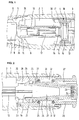
- the fountain pen shown has a tubular shaft 1 which contains a storage space 2 and a reserve space 3 which are separated from one another by a refill valve 4.
- a writing tip 6 Attached to the end 5 of the shaft 1 adjacent to the storage space 2 is a writing tip 6 (not shown in more detail) which contains an ink regulator 7 which has capillary channels and compensation chambers and which has an application element, e.g. a pen with the storage room 2 connects.
- the ink regulator 7 is connected via a bore 8 to the storage space 2, which can be closed by a separating valve 9.
- the isolating valve 9 is formed by a tubular closure element 10 made of elastomeric material and a conical seat 11 adjacent to the bore 8, against which the closure element 10 can be pressed.
- the closure element 10 surrounds the end 12 of a plunger 13 which projects into the storage space 2 and carries the closure element 14 of the refill valve 4. To hold the closure element 10 in place, the end 12 has a bead 15 which the closure element 10 encompasses elastically. In the axial direction, the closure element 10 is additionally supported on the closure element 14. The seat 11 are adjacent within the storage space 2 ribs 35, which promote the flow of ink through the open isolation valve.
- the closure element 14 has the shape of a cylindrical piston which carries a sealing ring 16 in an annular groove in its outer surface.
- the sealing ring 16 bears against a seat surface 17 formed by a cylindrical bore, which is formed on a sleeve-shaped component 18 which forms a partition between the storage space 2 and the reserve space 3.
- the closing element 10 opposite end 19 of The plunger 13 is fastened to a pushbutton 20 which is mounted in an axially movable manner in a sleeve-shaped carrier element 21 at the end of the shaft 1 opposite the writing tip 6.
- the pushbutton 20 has a longitudinal bore 22, in which the cross-shaped end 19 engages. In the axial direction, the end 19 is held by projections 23 which are engaged in undercut slots in the wall of the push button 20.
- has a compression spring 25 is arranged in a recess 24 in the lateral surface of the push button 20.
- the compression spring 25 is supported at one end on the push button 20 and at the other end on the support element 21 and thereby holds the push button 20 in the position shown, in which it protrudes from the support element 21 and with a stop surface 26 delimiting the recess 24 a collar 27 of the carrier element 21 protruding into the recess 24.
- the carrier element 21 has a cylindrical bore 28, in which the end of the pushbutton 20 facing the reserve space is sealed with a sliding sealing ring 29.
- the carrier element 21 is inserted into the open end of the shaft 1 and sealed with a sealing ring 30 with respect to the shaft 1.
- spring tongues 31 are formed on the carrier element 21 and are latched with projections at their ends in recesses 32 in the wall of the shaft 1.
- a wall 33 made of elastomeric material is arranged in the longitudinal bore 22 of the push button 20, which is accessible from the outside through a narrow bore 34 and has a pre-pierced opening 55 which is kept closed by the contraction behavior of the material.
- the opening 55 of the wall 33 can be pierced with a hollow needle of a refill container and then the reserve space can be filled again with ink through the hollow needle.
- the air that is displaced when filling in new ink is replaced by constantly changing the pressure in the Refill container sucked intermittently over the hollow needle.
- the wall 33 seals the hollow needle during refilling and behaves like an automatically closing valve. After pulling out the hollow needle, it contracts immediately so tightly that the opening 55 and the reserve space 3 are immediately sealed again.
- the pushbutton 20 is provided with a concentric annular groove 37 into which a guide tube of the refill container surrounding the hollow needle can be inserted.
- ink from the reserve space 3 can be refilled by pressing the pushbutton 20.
- the isolating valve 9 is first closed and thus the connection from the storage space 3 to the ink regulator 7 is interrupted by pressing the closure element 10 onto the seat 11.
- the refill valve 4 is opened by further pressing the pushbutton 20, the closure element 10 being elastically compressed in the longitudinal direction.
- the closure element 14 with its sealing ring 16 comes out of the seat 17 so that the ink can flow from the reserve space 3 into the storage space 2.
- the rinsing of the ink is facilitated by ribs 36 which adjoin the seat 17 within the storage space 2. Since in this process the storage space 2 is closed to the outside by the isolating valve 9, an overpressure existing in the reserve space 3 before the refill valve 4 opens cannot have a disadvantageous effect.
- the pushbutton 20 is released, as a result of which the compression spring 25 moves it back into the starting position.
- the refill valve 4 is closed first and then only the isolation valve 9 opened.
- the movement of the closure element 14 of the refill valve 4 causes an increase in the volume of the storage space 2 and thereby ensures a pressure reduction in the storage space 2 which is sufficient to prevent the opening of the separating valve 9 from being disturbed Prevent ink in the ink regulator.
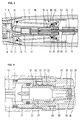
- FIG. 3 shows an embodiment of a fountain pen which, apart from the different design of the refill valve 4, is similar to the fountain pen shown in FIGS. 1 and 2.
- the refill valve 4 has a closure element 38 which is pressed against a valve seat 40 by a compression spring 39 arranged in the storage space 2.
- the valve seat 40 is formed by an annular collar in the bore of a sleeve 41 which is fastened in a liquid-tight manner in the shaft 1 and separates the storage space 2 from the reserve space 3.
- the closure element 38 consists of a valve plate 42, on which the compression spring 38 is supported, and a sealing element 43, which, in the closed position shown, bears against the valve seat 40 with a sealing surface on its outer edge.
- a cylindrical pin 44 extends through a central through-bore in the valve plate 42 and in the valve element 43 and firmly connects the tappet 13 to the tappet end 12.
- the pin 44 is sealed in the bore of the valve element 43.
- the pin 44 has a smaller diameter than the plunger 13 and the end 12 and the plunger 13 and the end 12 form mutually facing, radial stop surfaces 45, 46, between which the closure element 38 is displaceable on the pin 44 in the axial direction.
- the distance between the stop surfaces 45, 46 is somewhat larger than the sum of the axial length of the closure element 38 and the closing path of the isolating valve 9.
- the pin 44 slides through the closure element 38 and the stop surface 46 moves away from the valve plate 42, while the stop surface 45 approaches the valve element 43. Even before the stop surface 45 reaches the valve element 43, the end of the closure element 10 sits on the seat surface 11, as a result of which the isolating valve 9 closes. In the further course of the actuation movement of the plunger 13, in which the closure element 10 is compressed in the axial direction, the stop surface 45 reaches the sealing element 43 and moves it while compressing the compression spring 39 also to the left, whereby the refill valve 4 is opened.
- the ink from the reserve space 3 can now get into the storage space 2, supported by the capillary action of the ribs 36, the closed separating valve 9 preventing ink from being pressed into the ink regulator 7 and the writing tip at a higher pressure in the reserve space 3. If the storage space 2 is filled with ink, then after releasing the push button 20 by the compression springs 25 and 39, the refill valve 4 and the isolating valve 9 are moved back to their starting position in the reverse order.
- the pushbutton 20 is not moved directly, for example by axial finger pressure, but rather by the rotary movement of a rotary knob 47 which is rotatably attached to the open end of the shaft 1.
- the rotary knob 47 is in the form of a sleeve which surrounds the push button 20 and which is connected to the push button 20 by a thread 48.
- the rotary knob 47 is mounted on the carrier element 21 in the axial direction.
- the carrier element 21 has at its rear end a radially inwardly projecting collar 49 which engages in an annular groove in the lateral surface of the rotary knob 47.
- the carrier element 21 is slotted in the region of the collar 49, which makes it easier to insert the carrier element 21 and the rotary knob 47 into one another.
- the collar 49 In the installed position of the carrier element 21 in the shaft 1, the collar 49 is secured against radial expansion by the shaft 1, so that the rotary knob 47 cannot be released.
- an annular groove 37 is provided analogously to the exemplary embodiment according to FIG.
- the bottom surface 50 of the annular groove 37 is located on the rotary knob 47 and serves as a stop for the inward movement of the pushbutton 20 and for limiting the insertion depth of the guide tube.
- the pushbutton 20 is secured against rotation against the carrier element 21 by a projection 51 which engages in a longitudinal groove 52 which cuts the threads on the outside of the pushbutton. If the rotary knob 47 is rotated clockwise from the right to the left in FIG. 4, the pushbutton 20 is moved to the left and, as previously described, the refill valve 4 and the isolating valve 9 are actuated via the plunger 13. In the end position, the pushbutton 4 rests on the bottom surface 50 with a stop surface 53. In this position, in which the refill valve 4 is open, the valve formed by the wall 33 is shifted inwards to such an extent that it can no longer be reached by the hollow needle of the refill container when the latter with its guide tube surrounding the hollow needle on the stop surface 50 is present.
- the actuation of the pushbutton 20 with the aid of a rotary knob has the advantage that the refill valve 4 and the isolating valve 9 cannot be actuated suddenly, for example by pushing open the fountain pen with its pushbutton-side end. This prevents mass forces acting on the ink from causing undesired ink transport to the writing tip during this process.
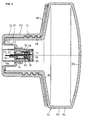
- the filling device shown in FIG. 5 is provided for filling a fountain pen according to FIGS. 1 to 4.
- she consists of a container 61 which is composed of an elastically deformable hollow body 62 and a rigid shell body 63.
- the hollow body 62 has a cylindrical wall 64, a slightly curved bottom 65 and a truncated cone-shaped cover 66, which is adjoined by a cylindrical neck 67.
- the neck 67 is provided with a thread 68 on its outside.
- the jacket body 63 has a frustoconical wall 69 and a cap 70 with an internal thread 71, which is screwed onto the neck 67 and closes it tightly.
- the inclination of the wall 69 corresponds to the cover 66 and its outer edge lies firmly on the edge of the cover 66.
- the bottom 72 of the cap 70 is provided with a depression 73 which projects into the neck 67 and is formed by cylindrical wall sections.
- a sleeve-shaped insert 75 which contains a valve 76 and a filling tube 77 designed as a hollow needle, is fastened in a bore 74 of the depression 73.
- the valve 76 consists of a wall 78 in the form of a cylindrical disk, onto which a sleeve-shaped extension 79 is formed.
- the wall 78 is pierced with a needle along its cylinder axis, whereby an automatically closing valve bore is formed.
- the wall 78 is held in the insert 75 by a ring 80.
- the filling tube 77 is arranged on the side of the wall 78 facing away from the interior of the container 61 and is guided at one end in the bore of the attachment 79. In the middle, the filling tube 77 is connected to a spring plate 81, which can be placed against an annular collar 82 of the insert 75 and is guided with a cylindrical guide section therein. A compression spring 83 is arranged between the spring plate 81 and the wall 78. The outer end of the insert 75 forms a guide sleeve 84 which surrounds the outer end of the filling tube 77 at a distance.
- the lower half of the illustration in FIG. 5 shows the filling tube 77 in its basic position, in which the valve 76 closed is. In this position, the filling tube 77 is held in contact with the collar 82 by the prestressed compression spring 83 with the spring plate 81.
- the container 61 with the guide sleeve 84 is pushed onto the pushbutton 20 at the end of the fountain pen and moved in the longitudinal direction of the guide tube 77, the guide sleeve 84 engages in the annular groove 37 and the outer end of the filling tube 77 protruding from the spring plate 81 penetrates the bore 34 and the opening 55 of the wall 33.
- the friction force to be overcome is absorbed by the prestressed compression spring 83.
- the compression spring 83 has the effect that the outer end of the guide tube 77 can only be pulled out of the wall 88 when the spring plate 81 abuts the annular collar 82 and the valve 76 formed by the wall 78 is already closed.
Landscapes
- Engineering & Computer Science (AREA)
- Mechanical Engineering (AREA)
- Pens And Brushes (AREA)
Priority Applications (1)
| Application Number | Priority Date | Filing Date | Title |
|---|---|---|---|
| EP96117137A EP0765769B1 (fr) | 1993-11-30 | 1994-11-09 | Instrument pour écrire, en particulier un stylographe |
Applications Claiming Priority (4)
| Application Number | Priority Date | Filing Date | Title |
|---|---|---|---|
| DE4340658 | 1993-11-30 | ||
| DE19934340760 DE4340760C2 (de) | 1993-11-30 | 1993-11-30 | Schreibgerät, insbesondere Füllhalter |
| DE4340760 | 1993-11-30 | ||
| DE4340658 | 1993-11-30 |
Related Child Applications (1)
| Application Number | Title | Priority Date | Filing Date |
|---|---|---|---|
| EP96117137A Division EP0765769B1 (fr) | 1993-11-30 | 1994-11-09 | Instrument pour écrire, en particulier un stylographe |
Publications (2)
| Publication Number | Publication Date |
|---|---|
| EP0655350A1 true EP0655350A1 (fr) | 1995-05-31 |
| EP0655350B1 EP0655350B1 (fr) | 1998-01-28 |
Family
ID=25931624
Family Applications (2)
| Application Number | Title | Priority Date | Filing Date |
|---|---|---|---|
| EP96117137A Expired - Lifetime EP0765769B1 (fr) | 1993-11-30 | 1994-11-09 | Instrument pour écrire, en particulier un stylographe |
| EP94117637A Expired - Lifetime EP0655350B1 (fr) | 1993-11-30 | 1994-11-09 | Instrument pour écrire, en particulier un stylographe |
Family Applications Before (1)
| Application Number | Title | Priority Date | Filing Date |
|---|---|---|---|
| EP96117137A Expired - Lifetime EP0765769B1 (fr) | 1993-11-30 | 1994-11-09 | Instrument pour écrire, en particulier un stylographe |
Country Status (5)
| Country | Link |
|---|---|
| US (1) | US5888008A (fr) |
| EP (2) | EP0765769B1 (fr) |
| JP (1) | JP2680276B2 (fr) |
| DE (2) | DE59405170D1 (fr) |
| ES (2) | ES2113035T3 (fr) |
Cited By (1)
| Publication number | Priority date | Publication date | Assignee | Title |
|---|---|---|---|---|
| US6892641B2 (en) | 2002-04-08 | 2005-05-17 | Komori Corporation | Plate holding apparatus |
Families Citing this family (15)
| Publication number | Priority date | Publication date | Assignee | Title |
|---|---|---|---|---|
| WO2000076862A1 (fr) * | 1999-06-14 | 2000-12-21 | International Paper Company | Structure stratifiee multicouche de resine/papier contenant au moins une couche composite de polymere/argile nanoparticulaire et materiaux d'emballage fabriques |
| US6531669B1 (en) * | 2001-05-02 | 2003-03-11 | Rockwell Collins, Inc. | Method and system for illuminating a mechanical rotary push-button switch |
| EP1607238B1 (fr) * | 2003-03-04 | 2010-05-05 | Mitsubishi Pencil Co., Ltd. | Recharge pour crayon correcteur et unite de recharge |
| JP4442798B2 (ja) * | 2003-03-04 | 2010-03-31 | 三菱鉛筆株式会社 | 修正ペン用リフィール |
| CN100381295C (zh) * | 2006-01-17 | 2008-04-16 | 徐辰丁 | 一种吸墨装置 |
| US8092108B2 (en) * | 2009-12-30 | 2012-01-10 | Harry Bainbridge | Porous tip liquid applicator having draw fill mechanism |
| JP5794732B2 (ja) * | 2011-08-22 | 2015-10-14 | 三菱鉛筆株式会社 | 補充具および補充具を備えた筆記具セット |
| CN102431714B (zh) * | 2011-12-14 | 2014-02-12 | 东莞怡信磁碟有限公司 | 一种便携式充液瓶的充液嘴转接器 |
| EP2920003B1 (fr) * | 2012-12-06 | 2019-08-07 | Europe Brands S.à r.l. | Ensemble de libération de bouchon de remplissage et instrument d'écriture le comportant |
| US9103376B2 (en) * | 2013-10-23 | 2015-08-11 | Hamilton Sundstrand Corporation | Chambered shaft for improved bearing lubrication |
| US9537811B2 (en) | 2014-10-02 | 2017-01-03 | Snap Inc. | Ephemeral gallery of ephemeral messages |
| JP6514480B2 (ja) * | 2014-10-16 | 2019-05-15 | 株式会社呉竹 | インク充填具 |
| JP7416669B2 (ja) * | 2020-06-23 | 2024-01-17 | ゼブラ株式会社 | インク補給具及び補給式筆記具セット |
| DE102020122970A1 (de) | 2020-09-02 | 2022-03-03 | Montblanc-Simplo Gmbh | Füllfederhalter mit schnellfüllkupplung |
| JP7695692B2 (ja) * | 2021-05-28 | 2025-06-19 | 株式会社呉竹 | 尾栓及び筆記具 |
Citations (8)
| Publication number | Priority date | Publication date | Assignee | Title |
|---|---|---|---|---|
| GB191506570A (en) * | 1915-05-03 | 1916-02-24 | Alexander Munro | Improvements in Fountain Pens. |
| CH255993A (de) * | 1947-05-01 | 1948-07-31 | Ag Saturn | Verfahren und Vorrichtung für die Nachfüllung von Flüssigkeiten in den Hohlraum von Gebrauchsgeräten mit Flüssigkeitsverbrauch. |
| US2603188A (en) * | 1949-07-26 | 1952-07-15 | Mckay Neil | Fountain pen |
| US2737329A (en) * | 1952-09-04 | 1956-03-06 | Bolsey Jacques | Filling apparatus for pens and the like |
| US2938499A (en) * | 1956-07-20 | 1960-05-31 | Lindenbaum Bernard | Combination pen and pressurized filling means |
| DE1210716B (de) * | 1961-03-24 | 1966-02-10 | Theodor Kovacs | Behaelter zum Fuellen von Tintenpatronen fuer Fuellfederhalter |
| EP0418397A1 (fr) * | 1989-03-28 | 1991-03-27 | Pentel Kabushiki Kaisha | Dispositif de decharge de fluide |
| EP0621140A1 (fr) * | 1993-04-15 | 1994-10-26 | Storelic Ag | Dispositif d'écriture rechargeable et récipient de recharge |
Family Cites Families (6)
| Publication number | Priority date | Publication date | Assignee | Title |
|---|---|---|---|---|
| DE33630C (de) * | A. FRANKE in Hermsdorf, Kreis Waldenburg | Maschine zum Zerkleinern gekochten Viehfutters | ||
| DE255993C (fr) | 1911-07-13 | 1913-01-27 | ||
| US2646777A (en) | 1950-12-28 | 1953-07-28 | Jorge S Zarur | Fountain pen |
| US3023737A (en) * | 1959-01-02 | 1962-03-06 | Marban Julian Gutierrez | Writing instrument |
| JPS62109980U (fr) * | 1985-08-08 | 1987-07-13 | ||
| JPH055024Y2 (fr) * | 1986-10-06 | 1993-02-09 |
-
1994
- 1994-11-09 DE DE59405170T patent/DE59405170D1/de not_active Expired - Lifetime
- 1994-11-09 ES ES94117637T patent/ES2113035T3/es not_active Expired - Lifetime
- 1994-11-09 DE DE59409687T patent/DE59409687D1/de not_active Expired - Fee Related
- 1994-11-09 ES ES96117137T patent/ES2155917T3/es not_active Expired - Lifetime
- 1994-11-09 EP EP96117137A patent/EP0765769B1/fr not_active Expired - Lifetime
- 1994-11-09 EP EP94117637A patent/EP0655350B1/fr not_active Expired - Lifetime
- 1994-11-30 JP JP6297069A patent/JP2680276B2/ja not_active Expired - Fee Related
-
1997
- 1997-05-13 US US08/854,924 patent/US5888008A/en not_active Expired - Fee Related
Patent Citations (8)
| Publication number | Priority date | Publication date | Assignee | Title |
|---|---|---|---|---|
| GB191506570A (en) * | 1915-05-03 | 1916-02-24 | Alexander Munro | Improvements in Fountain Pens. |
| CH255993A (de) * | 1947-05-01 | 1948-07-31 | Ag Saturn | Verfahren und Vorrichtung für die Nachfüllung von Flüssigkeiten in den Hohlraum von Gebrauchsgeräten mit Flüssigkeitsverbrauch. |
| US2603188A (en) * | 1949-07-26 | 1952-07-15 | Mckay Neil | Fountain pen |
| US2737329A (en) * | 1952-09-04 | 1956-03-06 | Bolsey Jacques | Filling apparatus for pens and the like |
| US2938499A (en) * | 1956-07-20 | 1960-05-31 | Lindenbaum Bernard | Combination pen and pressurized filling means |
| DE1210716B (de) * | 1961-03-24 | 1966-02-10 | Theodor Kovacs | Behaelter zum Fuellen von Tintenpatronen fuer Fuellfederhalter |
| EP0418397A1 (fr) * | 1989-03-28 | 1991-03-27 | Pentel Kabushiki Kaisha | Dispositif de decharge de fluide |
| EP0621140A1 (fr) * | 1993-04-15 | 1994-10-26 | Storelic Ag | Dispositif d'écriture rechargeable et récipient de recharge |
Cited By (1)
| Publication number | Priority date | Publication date | Assignee | Title |
|---|---|---|---|---|
| US6892641B2 (en) | 2002-04-08 | 2005-05-17 | Komori Corporation | Plate holding apparatus |
Also Published As
| Publication number | Publication date |
|---|---|
| DE59409687D1 (de) | 2001-04-19 |
| ES2155917T3 (es) | 2001-06-01 |
| EP0765769A2 (fr) | 1997-04-02 |
| EP0765769A3 (fr) | 1998-01-21 |
| US5888008A (en) | 1999-03-30 |
| EP0765769B1 (fr) | 2001-03-14 |
| EP0655350B1 (fr) | 1998-01-28 |
| JPH07251587A (ja) | 1995-10-03 |
| JP2680276B2 (ja) | 1997-11-19 |
| DE59405170D1 (de) | 1998-03-05 |
| ES2113035T3 (es) | 1998-04-16 |
Similar Documents
| Publication | Publication Date | Title |
|---|---|---|
| EP0655350B1 (fr) | Instrument pour écrire, en particulier un stylographe | |
| DE69804319T2 (de) | Bürste | |
| DE602004002560T2 (de) | Nicht wiederauffüllbare ventilvorrichtung | |
| DE69012803T2 (de) | Aufbewahrungs- und umfüllflasche mit doppelter kammer. | |
| DE2725495C2 (de) | Spendeeinrichtung | |
| DE2641171C3 (de) | Schreibgerät | |
| DE2538971A1 (de) | Sprueheinrichtung | |
| CH652372A5 (de) | Vorrichtung zur ausgabe von pastoesen medien. | |
| DE102013211423A1 (de) | Mehrschichtiger Behälter | |
| DE4005528A1 (de) | Austragvorrichtung fuer medien | |
| DE3425900C2 (de) | Vorrichtung mit Tropfenzähler zum Abgeben einer flüssigen oder pastösen Substanz | |
| DE3802682A1 (de) | Fluessigkeitsspender | |
| EP2624722B1 (fr) | Applicateur pour un fluide à appliquer | |
| DE3234514C2 (de) | Schreibgerät mit Verschlußkappe | |
| EP2184180B1 (fr) | Instrument d'écriture avec un capuchon de fermeture | |
| EP0621140B1 (fr) | Dispositif d'écriture rechargeable et récipient de recharge | |
| DE69110458T2 (de) | Abgabevorrichtung. | |
| DE1152368B (de) | Ventilanordnung zur dosierten Abgabe von unter Druck stehenden Fluessigkeiten aus einem Behaelter | |
| EP0912413B1 (fr) | Robinet en plastique pour contenant a liquide | |
| CH652974A5 (de) | Fuellminenstift mit auswechselbarem minenvorratsbehaelter. | |
| DE3629627C1 (de) | Stiftfoermige Vorrichtung zum Abgeben von fliessfaehigen Massen aus einem Vorratsbehaelter | |
| DE69029939T2 (de) | Füllfederhalter | |
| DE1291257B (de) | Schreibgeraet | |
| EP0673322B1 (fr) | Recipient de remplissage pour un dispositif permettant d'ecrire, de marquer, de peindre ou de dessiner | |
| DE19703853A1 (de) | Nachfüllbares Schreibgerät, insbesondere Füllhalter, und Nachfüllbehälter |
Legal Events
| Date | Code | Title | Description |
|---|---|---|---|
| PUAI | Public reference made under article 153(3) epc to a published international application that has entered the european phase |
Free format text: ORIGINAL CODE: 0009012 |
|
| 17P | Request for examination filed |
Effective date: 19941109 |
|
| AK | Designated contracting states |
Kind code of ref document: A1 Designated state(s): CH DE ES FR GB IT LI |
|
| 17Q | First examination report despatched |
Effective date: 19960621 |
|
| GRAG | Despatch of communication of intention to grant |
Free format text: ORIGINAL CODE: EPIDOS AGRA |
|
| GRAG | Despatch of communication of intention to grant |
Free format text: ORIGINAL CODE: EPIDOS AGRA |
|
| GRAH | Despatch of communication of intention to grant a patent |
Free format text: ORIGINAL CODE: EPIDOS IGRA |
|
| GRAH | Despatch of communication of intention to grant a patent |
Free format text: ORIGINAL CODE: EPIDOS IGRA |
|
| GRAA | (expected) grant |
Free format text: ORIGINAL CODE: 0009210 |
|
| AK | Designated contracting states |
Kind code of ref document: B1 Designated state(s): CH DE ES FR GB IT LI |
|
| XX | Miscellaneous (additional remarks) |
Free format text: TEILANMELDUNG 96117137.8 EINGEREICHT AM 25/10/96. |
|
| REG | Reference to a national code |
Ref country code: CH Ref legal event code: EP |
|
| REF | Corresponds to: |
Ref document number: 59405170 Country of ref document: DE Date of ref document: 19980305 |
|
| ET | Fr: translation filed | ||
| REG | Reference to a national code |
Ref country code: ES Ref legal event code: FG2A Ref document number: 2113035 Country of ref document: ES Kind code of ref document: T3 |
|
| ITF | It: translation for a ep patent filed | ||
| REG | Reference to a national code |
Ref country code: CH Ref legal event code: NV Representative=s name: BRAUN & PARTNER PATENT-, MARKEN-, RECHTSANWAELTE |
|
| GBT | Gb: translation of ep patent filed (gb section 77(6)(a)/1977) |
Effective date: 19980430 |
|
| PLBE | No opposition filed within time limit |
Free format text: ORIGINAL CODE: 0009261 |
|
| STAA | Information on the status of an ep patent application or granted ep patent |
Free format text: STATUS: NO OPPOSITION FILED WITHIN TIME LIMIT |
|
| 26N | No opposition filed | ||
| REG | Reference to a national code |
Ref country code: GB Ref legal event code: IF02 |
|
| REG | Reference to a national code |
Ref country code: CH Ref legal event code: PUE Owner name: PELIKAN GMBH TRANSFER- PELIKAN PBS-PRODUKTIONSGESE |
|
| REG | Reference to a national code |
Ref country code: GB Ref legal event code: 732E |
|
| REG | Reference to a national code |
Ref country code: FR Ref legal event code: TP |
|
| PGFP | Annual fee paid to national office [announced via postgrant information from national office to epo] |
Ref country code: GB Payment date: 20051025 Year of fee payment: 12 |
|
| PGFP | Annual fee paid to national office [announced via postgrant information from national office to epo] |
Ref country code: FR Payment date: 20051118 Year of fee payment: 12 |
|
| PGFP | Annual fee paid to national office [announced via postgrant information from national office to epo] |
Ref country code: ES Payment date: 20051122 Year of fee payment: 12 |
|
| PGFP | Annual fee paid to national office [announced via postgrant information from national office to epo] |
Ref country code: CH Payment date: 20051123 Year of fee payment: 12 |
|
| PG25 | Lapsed in a contracting state [announced via postgrant information from national office to epo] |
Ref country code: LI Free format text: LAPSE BECAUSE OF NON-PAYMENT OF DUE FEES Effective date: 20061130 Ref country code: CH Free format text: LAPSE BECAUSE OF NON-PAYMENT OF DUE FEES Effective date: 20061130 |
|
| PGFP | Annual fee paid to national office [announced via postgrant information from national office to epo] |
Ref country code: IT Payment date: 20061130 Year of fee payment: 13 |
|
| REG | Reference to a national code |
Ref country code: CH Ref legal event code: PL |
|
| GBPC | Gb: european patent ceased through non-payment of renewal fee |
Effective date: 20061109 |
|
| REG | Reference to a national code |
Ref country code: FR Ref legal event code: ST Effective date: 20070731 |
|
| PG25 | Lapsed in a contracting state [announced via postgrant information from national office to epo] |
Ref country code: GB Free format text: LAPSE BECAUSE OF NON-PAYMENT OF DUE FEES Effective date: 20061109 |
|
| REG | Reference to a national code |
Ref country code: ES Ref legal event code: FD2A Effective date: 20061110 |
|
| PG25 | Lapsed in a contracting state [announced via postgrant information from national office to epo] |
Ref country code: FR Free format text: LAPSE BECAUSE OF NON-PAYMENT OF DUE FEES Effective date: 20061130 Ref country code: ES Free format text: LAPSE BECAUSE OF NON-PAYMENT OF DUE FEES Effective date: 20061110 |
|
| PG25 | Lapsed in a contracting state [announced via postgrant information from national office to epo] |
Ref country code: IT Free format text: LAPSE BECAUSE OF NON-PAYMENT OF DUE FEES Effective date: 20071109 |
|
| PGFP | Annual fee paid to national office [announced via postgrant information from national office to epo] |
Ref country code: DE Payment date: 20110124 Year of fee payment: 17 |
|
| REG | Reference to a national code |
Ref country code: DE Ref legal event code: R119 Ref document number: 59405170 Country of ref document: DE Effective date: 20120601 |
|
| PG25 | Lapsed in a contracting state [announced via postgrant information from national office to epo] |
Ref country code: DE Free format text: LAPSE BECAUSE OF NON-PAYMENT OF DUE FEES Effective date: 20120601 |