EP0655406B1 - Dispositif d'alimentation de matériau en bande - Google Patents
Dispositif d'alimentation de matériau en bande Download PDFInfo
- Publication number
- EP0655406B1 EP0655406B1 EP19930830476 EP93830476A EP0655406B1 EP 0655406 B1 EP0655406 B1 EP 0655406B1 EP 19930830476 EP19930830476 EP 19930830476 EP 93830476 A EP93830476 A EP 93830476A EP 0655406 B1 EP0655406 B1 EP 0655406B1
- Authority
- EP
- European Patent Office
- Prior art keywords
- chamber
- piloting
- passage
- obturator
- inlet passage
- Prior art date
- Legal status (The legal status is an assumption and is not a legal conclusion. Google has not performed a legal analysis and makes no representation as to the accuracy of the status listed.)
- Expired - Lifetime
Links
- 238000006073 displacement reaction Methods 0.000 claims description 8
- 238000010276 construction Methods 0.000 description 2
- 230000002708 enhancing effect Effects 0.000 description 1
- 238000004519 manufacturing process Methods 0.000 description 1
- 238000007789 sealing Methods 0.000 description 1
Images

Classifications
-
- B—PERFORMING OPERATIONS; TRANSPORTING
- B65—CONVEYING; PACKING; STORING; HANDLING THIN OR FILAMENTARY MATERIAL
- B65H—HANDLING THIN OR FILAMENTARY MATERIAL, e.g. SHEETS, WEBS, CABLES
- B65H20/00—Advancing webs
- B65H20/16—Advancing webs by web-gripping means, e.g. grippers, clips
- B65H20/18—Advancing webs by web-gripping means, e.g. grippers, clips to effect step-by-step advancement of web
-
- B—PERFORMING OPERATIONS; TRANSPORTING
- B21—MECHANICAL METAL-WORKING WITHOUT ESSENTIALLY REMOVING MATERIAL; PUNCHING METAL
- B21D—WORKING OR PROCESSING OF SHEET METAL OR METAL TUBES, RODS OR PROFILES WITHOUT ESSENTIALLY REMOVING MATERIAL; PUNCHING METAL
- B21D43/00—Feeding, positioning or storing devices combined with, or arranged in, or specially adapted for use in connection with, apparatus for working or processing sheet metal, metal tubes or metal profiles; Associations therewith of cutting devices
- B21D43/02—Advancing work in relation to the stroke of the die or tool
- B21D43/04—Advancing work in relation to the stroke of the die or tool by means in mechanical engagement with the work
- B21D43/10—Advancing work in relation to the stroke of the die or tool by means in mechanical engagement with the work by grippers
- B21D43/11—Advancing work in relation to the stroke of the die or tool by means in mechanical engagement with the work by grippers for feeding sheet or strip material
-
- B—PERFORMING OPERATIONS; TRANSPORTING
- B65—CONVEYING; PACKING; STORING; HANDLING THIN OR FILAMENTARY MATERIAL
- B65H—HANDLING THIN OR FILAMENTARY MATERIAL, e.g. SHEETS, WEBS, CABLES
- B65H20/00—Advancing webs
- B65H20/06—Advancing webs by friction band
- B65H20/08—Advancing webs by friction band to effect step-by-step advancement of web
-
- Y—GENERAL TAGGING OF NEW TECHNOLOGICAL DEVELOPMENTS; GENERAL TAGGING OF CROSS-SECTIONAL TECHNOLOGIES SPANNING OVER SEVERAL SECTIONS OF THE IPC; TECHNICAL SUBJECTS COVERED BY FORMER USPC CROSS-REFERENCE ART COLLECTIONS [XRACs] AND DIGESTS
- Y10—TECHNICAL SUBJECTS COVERED BY FORMER USPC
- Y10T—TECHNICAL SUBJECTS COVERED BY FORMER US CLASSIFICATION
- Y10T137/00—Fluid handling
- Y10T137/8593—Systems
- Y10T137/86493—Multi-way valve unit
- Y10T137/86574—Supply and exhaust
- Y10T137/86622—Motor-operated
- Y10T137/8663—Fluid motor
Definitions
- the present invention is generally related to feeding of webs of any material towards a work station, particularly but not exclusively to a forming press.
- the invention is directed to a feeding device for web material, of the type comprising step-feed means of the web along a longitudinal direction comprising a stationary gripper and a movable gripper, a pneumatic actuator assembly for operating linear alternative forward and back displacement of the movable gripper relative to the stationary gripper parallelly to said longitudinal direction and opening and closure of said grippers in synchronism with the alternative displacement of the movable gripper, and an adjustable stop member cooperating with the movable gripper at the end of the forward displacement thereof.
- the pneumatic actuator assembly traditionally comprises a block incorporating a three-way pneumatically piloted control valve, which controls the communication between said pneumatic actuator assembly and, respectively, a source of air under pressure and a discharge port.
- Feeding devices of the above mentioned type are currently manufactured and marketed for instance by ELMER of Turin, Italy and are also generally known from US-A-4,175,688.
- the control valve traditionally comprises a hollow body having an inlet axial passage communicating with a feeding line from said pressurised air source, a radial inlet passage communicating with a pneumatic piloting line, a first and a second radial outlet passages respectively communicating with the pneumatic actuator assembly and with the discharge, and a spool having at one end thereof a plunger subject to the pressure from the piloting line, and having at the other end thereof a floating obturator which, in presence of the piloting pressure, face-sealingly closes said inlet axial passage and opens the communication between the first and the second radial outlet passages, and in the absence of the piloting pressure closes the second radial outlet passage and opens the communication between the inlet axial passage and the first radial outlet passage.
- the pneumatic pressure in presence of piloting pressure the pneumatic
- FIG. 1 A feeding device for web material according to the prior art, provided with such a control valve, is shown in figures 1 through 4 of the drawings, in which:
- reference numeral 1 generally designates a feeding device for web material according to the prior art, which is intended to be combined with a support and guide system of a web, known per se and not shown in the drawings.
- the feeding device 1 comprises, briefly, a block 2 carrying a stationary gripper 3, a movable gripper 4 displaceable along guides 5 according to a linear alternative motion parallelly to a longitudinal feed direction F of the web, and an adjustable stop member 6 cooperating with the movable gripper 4 at the end of the forward displacement thereof.
- Displacement of the movable gripper 4 and opening and closure of the stationary gripper 3 and of the movable gripper 4 are operated by means of a pneumatic actuator assembly, not shown in the drawings for the sake of brevity, which is incorporated within the block 2 and is in turn controlled by means of an actuating valve device 7, directly operated mechanically, for instance by the forming press to which the feeding device 1 may be in use associated, or by a pneumatic or electropneumatic remote control, even in a way known per se.
- the pneumatic actuator assembly incorporated in the block 2 includes a three-way control valve 8, named as "secondary valve", controlling the communication between the pneumatic actuator assembly and, respectively, an external source of pressurised air (not shown) and a discharge port.
- secondary valve controlling the communication between the pneumatic actuator assembly and, respectively, an external source of pressurised air (not shown) and a discharge port.
- control valve 8 comprises a hollow body 9 housed within a rear cylindrical seat 10 of the block 2 and defining a first chamber 11 and a second elongated chamber 12, coaxial to each other.
- the first chamber 12 is connected, at the end thereof opposite to the first chamber 11, with an axial inlet passage 13 formed through the valve body 9 and communicating with a feed line A, formed within the block 2 and connected to the source of air under pressure.
- the first chamber 11 is connected, in correspondence of the end thereof opposite to the second chamber 12, with one or more radial inlet passages 14 communicating, through an annular chamber 15 formed in the valve body 9, with a pneumatic piloting line D formed within the block 2, and in turn controlled by means of the control valve 7.
- the chamber 12 is further connected, on the side of the chamber 11, with one or more radial passages 16 communicating with an annular chamber 24 formed in the valve body 9 and in turn communicating with a feed line B to the pneumatic actuator group, formed within the body 2.
- the chamber 12 On the side of the axial passage 13, the chamber 12 is connected through a single radial passage 17 and an annular chamber 18 formed in the valve body 9, with a discharge line C also formed within the block 2.
- Reference 19 designates a spool which is axially movable within the valve body 9, and which is formed at one end thereof with a plunger 20 sealingly slidable along the first chamber 11, and at the other end with a stem 21 extending coaxially into the second chamber 12.
- An obturator 22, floating within the chamber 12, is adjacent to the stem 21.
- the obturator 22 has a cylindrical shape with a cross section which is smaller than that of the chamber 12, so as to define with the wall of the latter an axial passage 23, as explained below.
- the radial discharge passage 17 is thus closed, while communication between the axial feed passage 13 and the radial outlet passages 16 is open through the axial passage 23, whereby the air under pressure from the feed line A is fed through the line B to the pneumatic actuator assembly, so as to perform the operating functions of the web feeding device 1.
- the spool 19 In presence of the piloting pressure in the line D, the spool 19 is instead placed in the position shown in figure 3, in which it is shifted on the right with reference to the drawing, whereby the actuator 22 face-sealingly closes the axial feed passage 13, while opening the communication between the radial passages 16 and 17, i.e. between the line B connected to the pneumatic actuator assembly and the discharge line C.
- the lateral wall of this obturator 22 is no more able to adhere with a sufficient seal onto the corresponding area of the wall of the chamber 12 and, consequently, in the absence of piloting pressure it is not possible to obtain an airtight closure of the radial discharge passage 17.
- the object of the present invention is to overcome the above mentioned drawback, and to provide a web material feeding device of the type set forth at the beginning, the control valve of which enables, while maintaining a simple and cheap construction, an appreciable increase of the rate of flow of the air fed to the pneumatic actuator assembly, ensuring at the same time a perfect airtight closure of the discharge passage in the corresponding condition of use, i.e. in the absence of the piloting pressure.
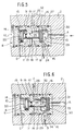
- the cavity of the valve body 9 of the control valve 8 is formed, starting from the chamber 11 communicating with the piloting line D through the radial passages 14 and the annular chamber 15, with a restricted section 25 for guiding the stem 21, followed by an intermediate chamber 26 and by a second enlarged chamber 27.
- the intermediate chamber 26 communicates, through a series of radial passages 17 and the annular chamber 18, with the discharge line C.
- the second chamber 26, axially connected with the inlet passage 13 communicating with the feed line A, is connected in correspondence of a central area thereof, with the radial passages 16 and with the annular chamber 24 communicating with the line B connected to the pneumatic actuator assembly.
- valve body 9 defines an annular face seal seat 29.
- the valve obturator is constituted by a floating disk 30 having a cylindrical shape, or a frusto-conical shape with the smaller end facing towards the inlet axial passage 13, which is coaxial with the stem 21 and whose lateral wall is in circumferential sliding contact with the wall of the second chamber 27.
- the axial dimension of the obturator 30 is substantially corresponding to the distance between the radial passages 16 and the annular face seal seat 29, on one side, and between the passages 16 and the bottom of the second chamber 27 connected to the axial inlet passage 13, on the other side.
- the face of the obturator 30 facing towards the feed passage A defines a first face seal surface 31, and its opposite face, i.e. that facing towards the intermediate chamber 26, defines a second face seal surface 32 adapted to cooperate with the annular face seal seat 29.
- the spool 19 In presence of the piloting pressure, the spool 19 is placed in the position shown in figure 6, i.e. is shifted to the right with reference to the drawings. In this condition the first face seal surface 31 of the obturator 30 is maintained into airtight contact against the bottom of the chamber 27, thus interrupting the communication with the feed passage A, while the line B of the pneumatic actuator assembly is in communication, through the intermediate chamber 26, with the discharge line C.
- control valve 8 enables a substantial increase of the rate of flow of the air fed by the feed line A to the line B connected to the pneumatic actuator assembly, without negatively affecting airtight closure of the discharge line C, in presence of the piloting pressure.
- any increase of the air rate of flow increases the sealing thrust of the face seal surface 32 of the obturator 30 against the corresponding annular face seal seat 29.
Landscapes
- Engineering & Computer Science (AREA)
- Mechanical Engineering (AREA)
- Multiple-Way Valves (AREA)
Claims (2)
- Dispositif d'alimentation (1) destiné à assurer l'alimentation d'un poste de travail en bande continue, en particulier d'une presse de formage, comprenant un dispositif d'avance par pas de la bande continue dans une direction longitudinale (F), comprenant un organe fixe de saisie (3) et un organe mobile de saisie (4), un ensemble à organe pneumatique de manoeuvre (B) destiné à commander le déplacement alternatif linéaire vers l'avant et vers l'arrière de l'organe mobile de saisie (4) par rapport à l'organe fixe de saisie (3) parallèlement à la direction longitudinale (F), et à ouvrir et fermer les organes de saisie en synchronisme avec le déplacement alternatif de l'organe mobile de saisie (4), et un organe réglable d'arrêt (6) coopérant avec l'organe mobile de saisie (4) à l'extrémité de son déplacement vers l'avant, et dans lequel l'ensemble à organe pneumatique de manoeuvre (B) comporte un bloc (2) comprenant un distributeur (8) de commande à trois voies piloté pneumatiquement, commandant la communication entre l'ensemble à organe pneumatique de manoeuvre et, respectivement, une source d'air comprimé (A) et une évacuation (C), le distributeur de commande (8) comprenant un corps creux (9) ayant un passage axial d'entrée (13) qui communique avec une canalisation d'alimentation (A) à partir de la source d'air comprimé, un passage radial d'entrée (14) qui communique avec une canalisation pneumatique de pilotage (D), et un premier et un second passage radial de sortie (16, 17) qui communiquent respectivement avec l'ensemble à organe pneumatique de manoeuvre (B) et avec l'évacuation (C), et un tiroir (19) dont une première extrémité possède un plongeur (20) soumis à une pression de la canalisation de pilotage (D) et dont l'autre extrémité possède un obturateur flottant (30) ayant une première surface d'étanchéité contre une face qui, en présence de la pression de pilotage, coopère de façon étanche contre sa face pour fermer le passage axial d'entrée (13) et ouvrir la communication entre le premier et le second passage de sortie (16, 17) et, en l'absence de la pression de pilotage, ferme le second passage radial de sortie (17) et ouvre la communication entre le passage axial d'entrée (13) et le premier passage de sortie (16), caractérisé en ce que l'obturateur (30) du distributeur de commande (8) a une seconde surface (32) d'étanchéité contre sa face coopérant de façon étanche en direction axiale, en l'absence de la pression de pilotage, avec une surface correspondante d'étanchéité (29) contre la surface du corps (9) du distributeur afin que le second passage de sortie (17) soit fermé.
- Dispositif d'alimentation selon la revendication 1, caractérisé en ce que :- le corps (9) du distributeur de commande (8) possède une première chambre (11) dans laquelle le plongeur (20) du tiroir (19) peut coulisser axialement de manière étanche, et une seconde chambre (27) dans laquelle l'obturateur flottant (30) est mobile axialement, et une cavité intermédiaire (26) comprise entre la première et la seconde chambre (11, 27), la première chambre (11) étant reliée au passage radial d'entrée (14), la seconde chambre (27) étant reliée au passage axial d'entrée (13) et au premier passage radial de sortie (16), et la cavité intermédiaire (26) étant reliée au second passage radial de sortie (17),- un siège annulaire délimitant la surface d'étanchéité (29) du corps d'obturateur (9) est placé entre la seconde chambre (27) et la cavité intermédiaire (26), et- l'obturateur flottant (30) est constitué d'un élément sous forme de disque ayant une surface tournée vers la cavité intermédiaire (26) et délimitant la seconde surface (32) d'étanchéité contre la face de l'obturateur (30), destinée à coopérer avec le siège annulaire (29) du corps de distributeur (9) en l'absence de la pression de pilotage, et la face opposée délimitant une autre surface (31) d'étanchéité contre la face tournée vers le passage axial d'entrée (13).
Priority Applications (4)
| Application Number | Priority Date | Filing Date | Title |
|---|---|---|---|
| US08/159,261 US5513790A (en) | 1993-11-30 | 1993-11-30 | Face sealing air actuated valve in an intermittent feed device |
| EP19930830476 EP0655406B1 (fr) | 1993-11-30 | 1993-11-30 | Dispositif d'alimentation de matériau en bande |
| DE69309286T DE69309286T2 (de) | 1993-11-30 | 1993-11-30 | Zuführeinrichtung für bandförmiges Gut |
| ES93830476T ES2101283T3 (es) | 1993-11-30 | 1993-11-30 | Dispositivo de alimentacion de material en banda. |
Applications Claiming Priority (2)
| Application Number | Priority Date | Filing Date | Title |
|---|---|---|---|
| US08/159,261 US5513790A (en) | 1993-11-30 | 1993-11-30 | Face sealing air actuated valve in an intermittent feed device |
| EP19930830476 EP0655406B1 (fr) | 1993-11-30 | 1993-11-30 | Dispositif d'alimentation de matériau en bande |
Publications (2)
| Publication Number | Publication Date |
|---|---|
| EP0655406A1 EP0655406A1 (fr) | 1995-05-31 |
| EP0655406B1 true EP0655406B1 (fr) | 1997-03-26 |
Family
ID=26134913
Family Applications (1)
| Application Number | Title | Priority Date | Filing Date |
|---|---|---|---|
| EP19930830476 Expired - Lifetime EP0655406B1 (fr) | 1993-11-30 | 1993-11-30 | Dispositif d'alimentation de matériau en bande |
Country Status (4)
| Country | Link |
|---|---|
| US (1) | US5513790A (fr) |
| EP (1) | EP0655406B1 (fr) |
| DE (1) | DE69309286T2 (fr) |
| ES (1) | ES2101283T3 (fr) |
Families Citing this family (4)
| Publication number | Priority date | Publication date | Assignee | Title |
|---|---|---|---|---|
| US6182880B1 (en) * | 1999-10-08 | 2001-02-06 | Herrblitz Modular System S.R.L. | Feeding device for strips |
| US8931577B2 (en) * | 2011-07-08 | 2015-01-13 | Cameron International Corporation | Double valve block and actuator assembly including same |
| US9913957B2 (en) * | 2012-12-05 | 2018-03-13 | Shenzhen Mindray Bio-Medical Electronics Co. Ltd. | Power switch for auxiliary common gas outlet |
| CN104786267B (zh) * | 2014-01-17 | 2017-06-20 | 禾昇织带有限公司 | 胶片定位送料机 |
Family Cites Families (10)
| Publication number | Priority date | Publication date | Assignee | Title |
|---|---|---|---|---|
| DE1189346B (de) * | 1961-08-05 | 1965-03-18 | Hardy Geb Maschf Ag | Dreiwegeschieber oder -ventil, insbesondere fuer die Notbetaetigung pneumatisch oder elektropneumatisch gesteuerter Tueranlagen |
| CH570918A5 (en) * | 1973-08-27 | 1975-12-31 | Samvaz Sa | Intermittent feeder for metal band or strip - for presses and similar machines, has rapid response and permits accurate feed regulation |
| US3937379A (en) * | 1974-09-06 | 1976-02-10 | Narwid Bernard V | Sheet material feed apparatus |
| US4051802A (en) * | 1975-09-04 | 1977-10-04 | Brunswick Corporation | Operating handle for pivotally mounted trolling motor |
| US4059212A (en) * | 1977-02-03 | 1977-11-22 | Plessey Incorporated | Stock feeder for punched stock |
| US4175688A (en) * | 1978-01-23 | 1979-11-27 | Scribner Albert W | Semi-automatic stock feeder |
| US4444346A (en) * | 1982-03-01 | 1984-04-24 | Scribner Albert W | Pneumatic feeder for punch presses |
| US4513899A (en) * | 1982-08-10 | 1985-04-30 | Plessey Incorporated | Stock feeder with adjustable width feed path |
| JPH0615186Y2 (ja) * | 1986-12-29 | 1994-04-20 | エスエムシー株式会社 | 方向切換弁 |
| US5062349A (en) * | 1990-03-19 | 1991-11-05 | Baroid Technology, Inc. | Fluid economizer control valve system for blowout preventers |
-
1993
- 1993-11-30 ES ES93830476T patent/ES2101283T3/es not_active Expired - Lifetime
- 1993-11-30 US US08/159,261 patent/US5513790A/en not_active Expired - Lifetime
- 1993-11-30 EP EP19930830476 patent/EP0655406B1/fr not_active Expired - Lifetime
- 1993-11-30 DE DE69309286T patent/DE69309286T2/de not_active Expired - Fee Related
Also Published As
| Publication number | Publication date |
|---|---|
| US5513790A (en) | 1996-05-07 |
| EP0655406A1 (fr) | 1995-05-31 |
| DE69309286T2 (de) | 1997-10-16 |
| DE69309286D1 (de) | 1997-04-30 |
| ES2101283T3 (es) | 1997-07-01 |
Similar Documents
| Publication | Publication Date | Title |
|---|---|---|
| US2747611A (en) | Control valve device | |
| EP0864792B1 (fr) | Soupape d'aspiration en arriére | |
| JP3809103B2 (ja) | ブースタパイロット弁 | |
| JPH10153269A (ja) | パイロットチェック弁付スピードコントローラ | |
| JPH0428922B2 (fr) | ||
| US5305777A (en) | Speed controller | |
| US4971115A (en) | Four-way poppet valve with hollow stem and four-port body | |
| KR100398079B1 (ko) | 압력/유량 제어밸브 | |
| EP0256622B1 (fr) | Soupape à diaphragme de contrôle directionnel | |
| US5513790A (en) | Face sealing air actuated valve in an intermittent feed device | |
| EP1361382A3 (fr) | Ensemble de soupapes pour la commande de l'écoulement du matériau dans une installation de revêtement | |
| JPH09512329A (ja) | 自己の媒体によって作動するバルブ | |
| EP0822361B1 (fr) | Régulateur de pression bridé à une vanne de commande à plusieurs étages | |
| KR19990076731A (ko) | 제동력 부스터 | |
| US6382243B2 (en) | Pressure-reducing valve | |
| US5097747A (en) | Pilot adjuster-connector for adjusting the speed of pneumatic pressure cylinders | |
| US4848416A (en) | Weft yarn insertion nozzle device | |
| US4374485A (en) | Single annular membrane type of pneumatic positioner | |
| US11293561B2 (en) | Low profile solenoid valve | |
| US3506035A (en) | Distributor device for fluids | |
| EP0097246A2 (fr) | Dispositif de valve pour mettre progressivement sous pression des systèmes pneumatiques | |
| US20250060765A1 (en) | A pressure-independent control valve with a fluid pressure distributing sleeve, and method of distributing fluid pressure | |
| US20170204980A1 (en) | Control valve | |
| EP0764803A1 (fr) | Soupape | |
| GB2267898A (en) | Web turning bar |
Legal Events
| Date | Code | Title | Description |
|---|---|---|---|
| PUAI | Public reference made under article 153(3) epc to a published international application that has entered the european phase |
Free format text: ORIGINAL CODE: 0009012 |
|
| AK | Designated contracting states |
Kind code of ref document: A1 Designated state(s): BE CH DE ES FR GB LI NL SE |
|
| 17P | Request for examination filed |
Effective date: 19950831 |
|
| 17Q | First examination report despatched |
Effective date: 19960503 |
|
| GRAG | Despatch of communication of intention to grant |
Free format text: ORIGINAL CODE: EPIDOS AGRA |
|
| GRAH | Despatch of communication of intention to grant a patent |
Free format text: ORIGINAL CODE: EPIDOS IGRA |
|
| GRAH | Despatch of communication of intention to grant a patent |
Free format text: ORIGINAL CODE: EPIDOS IGRA |
|
| GRAA | (expected) grant |
Free format text: ORIGINAL CODE: 0009210 |
|
| RAP1 | Party data changed (applicant data changed or rights of an application transferred) |
Owner name: HERRBLITZ MODULAR SYSTEM SRL |
|
| RIN1 | Information on inventor provided before grant (corrected) |
Inventor name: GIUSTO, PLACIDO |
|
| AK | Designated contracting states |
Kind code of ref document: B1 Designated state(s): BE CH DE ES FR GB LI NL SE |
|
| PG25 | Lapsed in a contracting state [announced via postgrant information from national office to epo] |
Ref country code: LI Effective date: 19970326 Ref country code: CH Effective date: 19970326 Ref country code: BE Effective date: 19970326 |
|
| REG | Reference to a national code |
Ref country code: CH Ref legal event code: EP |
|
| REF | Corresponds to: |
Ref document number: 69309286 Country of ref document: DE Date of ref document: 19970430 |
|
| REG | Reference to a national code |
Ref country code: ES Ref legal event code: FG2A Ref document number: 2101283 Country of ref document: ES Kind code of ref document: T3 |
|
| ET | Fr: translation filed | ||
| REG | Reference to a national code |
Ref country code: CH Ref legal event code: PL |
|
| PGFP | Annual fee paid to national office [announced via postgrant information from national office to epo] |
Ref country code: SE Payment date: 19971013 Year of fee payment: 5 |
|
| PLBE | No opposition filed within time limit |
Free format text: ORIGINAL CODE: 0009261 |
|
| STAA | Information on the status of an ep patent application or granted ep patent |
Free format text: STATUS: NO OPPOSITION FILED WITHIN TIME LIMIT |
|
| 26N | No opposition filed | ||
| PGFP | Annual fee paid to national office [announced via postgrant information from national office to epo] |
Ref country code: ES Payment date: 19981102 Year of fee payment: 6 |
|
| PGFP | Annual fee paid to national office [announced via postgrant information from national office to epo] |
Ref country code: GB Payment date: 19981124 Year of fee payment: 6 |
|
| PGFP | Annual fee paid to national office [announced via postgrant information from national office to epo] |
Ref country code: NL Payment date: 19981130 Year of fee payment: 6 |
|
| PG25 | Lapsed in a contracting state [announced via postgrant information from national office to epo] |
Ref country code: SE Free format text: LAPSE BECAUSE OF NON-PAYMENT OF DUE FEES Effective date: 19981201 |
|
| PG25 | Lapsed in a contracting state [announced via postgrant information from national office to epo] |
Ref country code: GB Free format text: LAPSE BECAUSE OF NON-PAYMENT OF DUE FEES Effective date: 19991130 |
|
| PG25 | Lapsed in a contracting state [announced via postgrant information from national office to epo] |
Ref country code: ES Free format text: LAPSE BECAUSE OF NON-PAYMENT OF DUE FEES Effective date: 19991201 |
|
| PG25 | Lapsed in a contracting state [announced via postgrant information from national office to epo] |
Ref country code: NL Free format text: LAPSE BECAUSE OF NON-PAYMENT OF DUE FEES Effective date: 20000601 |
|
| GBPC | Gb: european patent ceased through non-payment of renewal fee |
Effective date: 19991130 |
|
| NLV4 | Nl: lapsed or anulled due to non-payment of the annual fee |
Effective date: 20000601 |
|
| REG | Reference to a national code |
Ref country code: ES Ref legal event code: FD2A Effective date: 20001214 |
|
| PGFP | Annual fee paid to national office [announced via postgrant information from national office to epo] |
Ref country code: FR Payment date: 20061108 Year of fee payment: 14 |
|
| PGFP | Annual fee paid to national office [announced via postgrant information from national office to epo] |
Ref country code: DE Payment date: 20061123 Year of fee payment: 14 |
|
| PG25 | Lapsed in a contracting state [announced via postgrant information from national office to epo] |
Ref country code: DE Free format text: LAPSE BECAUSE OF NON-PAYMENT OF DUE FEES Effective date: 20080603 |
|
| REG | Reference to a national code |
Ref country code: FR Ref legal event code: ST Effective date: 20080930 |
|
| PG25 | Lapsed in a contracting state [announced via postgrant information from national office to epo] |
Ref country code: FR Free format text: LAPSE BECAUSE OF NON-PAYMENT OF DUE FEES Effective date: 20071130 |