EP0655609B1 - Gehäuse für Messwertgeber - Google Patents
Gehäuse für Messwertgeber Download PDFInfo
- Publication number
- EP0655609B1 EP0655609B1 EP94117639A EP94117639A EP0655609B1 EP 0655609 B1 EP0655609 B1 EP 0655609B1 EP 94117639 A EP94117639 A EP 94117639A EP 94117639 A EP94117639 A EP 94117639A EP 0655609 B1 EP0655609 B1 EP 0655609B1
- Authority
- EP
- European Patent Office
- Prior art keywords
- protective sleeve
- cable holder
- housing
- housing parts
- casting compound
- Prior art date
- Legal status (The legal status is an assumption and is not a legal conclusion. Google has not performed a legal analysis and makes no representation as to the accuracy of the status listed.)
- Expired - Lifetime
Links
Images


Classifications
-
- G—PHYSICS
- G01—MEASURING; TESTING
- G01P—MEASURING LINEAR OR ANGULAR SPEED, ACCELERATION, DECELERATION, OR SHOCK; INDICATING PRESENCE, ABSENCE, OR DIRECTION, OF MOVEMENT
- G01P1/00—Details of instruments
- G01P1/02—Housings
- G01P1/026—Housings for speed measuring devices, e.g. pulse generator
-
- G—PHYSICS
- G01—MEASURING; TESTING
- G01D—MEASURING NOT SPECIALLY ADAPTED FOR A SPECIFIC VARIABLE; ARRANGEMENTS FOR MEASURING TWO OR MORE VARIABLES NOT COVERED IN A SINGLE OTHER SUBCLASS; TARIFF METERING APPARATUS; MEASURING OR TESTING NOT OTHERWISE PROVIDED FOR
- G01D11/00—Component parts of measuring arrangements not specially adapted for a specific variable
- G01D11/24—Housings ; Casings for instruments
- G01D11/245—Housings for sensors
Definitions
- the invention relates to a sensor with a two-part, in particular rod-shaped housing, one of which Housing part as an essentially cylindrical protective sleeve and its other housing part as a cable holder or Plug base and as a carrier of the functional elements of the Sensor is formed, of which the actual sensor after assembling the housing parts in the immediate vicinity the end wall of the protective sleeve is arranged.
- the object of the present invention was accordingly to design a sensor according to the generic term, that it complies with the conditions of mass production, if necessary can be mechanically assembled and compared to known Sensors with satisfactory functionality with significantly lower costs can be produced.
- This potting compound and the way it is used offer another advantage in that only relatively little Potting compound is required to the one hand Functional elements of the sensor in its head area to hold vibration-proof, on the other hand the cylindrical Snap connection and the column to which through the partition of the cable holder or connector base To seal contacts.
- the same casting compound is also for that Fix and covering the inaccessible in the cable holder isolated lines of the supplied cable can be used.
- the means only one potting compound is used and it is only a curing process for different and in relation to the encoder spatially separated sealing and embedding points required.
- the invention thus enables a particularly advantageous one Manufacturing the transducer by using as housing components only injection molded parts are provided, which without additional components by snapping together get connected. For the subsequent sealing of the gaps and Fixing of the functional elements is provided according to the Process only a relatively small amount of a single one Potting compound required. The assembly is therefore largely simplified and the material requirements reduced to a minimum.
- the view of the 1 shows the cable holder 2 and the Protective sleeve 3 assembled ready for installation.
- connected cable is a by means of a Corrugated tube 4 armored cable 5.
- One with the corrugated tube 4 pinched sleeve 6 serves as a coupling element, which with the Cable holder 2 is connected via a snap connection.
- Arm 7 formed, in which one with a through hole provided socket 8 is pressed.
- the arm 7 serves the Attachment of the transmitter 1 to, for example, one Gear housing, in which the protective sleeve 3 by a suitable opening protrudes.
- An O-ring 9 serves as Seal between the gear housing and the protective sleeve 3.
- An eyelet 10 is for the sealing of the fastening screw intended.
- FIG. 2 is an assembly instant during the assembly of cable holder 2 and protective sleeve 3 captured.
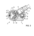
- the protective sleeve 3 was in a device in the simplest case in a plate 11, recorded by a pin 12 pressed into the plate 11, the Diameter the diameter of the through hole 13 (Fig. 3) in corresponds to the socket 8, aligned and up to that required level filled with potting compound 14.
- the device for a holder is a rational assembly formed a plurality of protective sleeves, the Housing the armored attached to the cable holders 2 Cables 4, 5 the number of assembly locations in the device limited.
- this problem does not exist if the sensor 1 is not hard-wired, but with a Connector base is equipped.
- a pot 19 formed, within which the Lines of the cable 5, one of which is designated 20, are distributed on through openings in the partition 17.
- the lines 20, which are inserted into the partition 17 Sealing sleeves 21 are assigned via cutting contacts 22 contacted with conductor tracks of a circuit board 23 which on the Cable holder 2 is attached.
- a frame serves the purpose of one leg is designated 24, the circuit board 23 as Edition, while a tongue 25 and latch 26 are provided to to hold the circuit board 23.
- the device 11 After the one pre-assembled unit ready for operation performing cable holder 2 is locked with the protective sleeve 3, the device 11 is turned so that the potting compound 14th also the partition 17 wetted and by capillary action in the existing column of cable bushings and in the Annular gap of the snap connection 15, 16 penetrates. After about The device 11 can be tilted back for 2 minutes.
- the curing of the potting compound required requires a minimum temperature of 80 o C and at this temperature an exposure time of at least 60 minutes.
- the membrane 33 accessible through the pocket 31 is pierced and the interior 18 of the protective sleeve 3 is subjected to an increased pressure. If no pressure drop is found, the sensor is tight and the puncture is closed by pressing a pin 35 into the bore 32.
Landscapes
- Physics & Mathematics (AREA)
- General Physics & Mathematics (AREA)
- Transmission And Conversion Of Sensor Element Output (AREA)
- Arrangements For Transmission Of Measured Signals (AREA)
- Connector Housings Or Holding Contact Members (AREA)
- Die Bonding (AREA)
- Fire-Detection Mechanisms (AREA)
- Cable Accessories (AREA)
- Switches Operated By Changes In Physical Conditions (AREA)
Description
Claims (3)
- Meßwertgeber mit einem zweiteiligen, insbesondere stabförmigen Gehäuse, dessen einer Gehäuseteil (3) als eine im wesentlichen zylindrische Schutzhülse und dessen anderer Gehäuseteil (2) als Kabelhalter oder Steckersockel sowie als Träger der Funktionselemente des Meßwertgebers ausgebildet ist, von denen der eigentliche Sensor (28) nach dem Zusammenfügen der Gehäuseteile in unmittelbarer Nähe der Stirnwand der Schutzhülse angeordnet ist,
dadurch gekennzeichnet,daß beide Gehäuseteile als Kunststoffspritzgußteile ausgebildet sind,daß an den Gehäuseteilen Mittel einer zylindrischen Schnappverbindung (15, 16) angeformt sind,daß an dem Steckersockel oder Kabelhalter (2) eine Trennwand (17) quer zur Geberachse mit Öffnungen zum Durchführen von Kontakten oder Leitungen (20) ausgebildet ist unddaß zum Fixieren der Funktionselemente (23, 27, 28), zum Abdichten der Leitungs- oder Kontaktdurchführungen und der Schnappverbindung (15, 16) eine einzige aushärtbare Vergußmasse (14, 34) Anwendung findet. - Verfahren zum Montieren eines stabförmigen Meßwertgebers nach Anspruch 1,
dadurch gekennzeichnet,daß die in einer Vorrichtung (11, 12) aufgenommene Schutzhülse (3) teilweise mit der Vergußmasse (14) gefüllt wird,daß der vormontierte Kabelhalter (2) bzw. Steckersockel in die Schutzhülse (3) eingeführt und die Schnappverbindungsmittel (15, 16) in Eingriff gebracht werden,daß der Meßwertgeber (1) in Achsebene um 180° gewendet und nach einer gewissen Zeit zurückgekippt wird,daß ein am Kabelhalter (2) bzw. Steckersockel ausgebildeter, dem Verteilen der Leitungen (20) bzw. dem Einführen eines Steckers dienender Raum (Topf 19) mehr oder weniger mit Vergußmasse (34) gefüllt wird unddaß der Meßwertgeber (1) zur Aushärtung der Vergußmasse (14, 34) einer Warmbehandlung zugeführt wird. - Verfahren nach Anspruch 2,
dadurch gekennzeichnet,daß nach dem Aushärtevorgang eine in der Trennwand (17) ausgebildete Membran (33) durchstoßen wird,daß der Raum (18) zwischen der Trennwand (17) und der Schutzhülse (3) unter Druck gesetzt und auf Dichtheit geprüft wird unddaß die Durchstoßstelle durch Verstiften abgedichtet wird.
Applications Claiming Priority (2)
| Application Number | Priority Date | Filing Date | Title |
|---|---|---|---|
| DE4340177 | 1993-11-25 | ||
| DE4340177A DE4340177A1 (de) | 1993-11-25 | 1993-11-25 | Meßwertgeber |
Publications (2)
| Publication Number | Publication Date |
|---|---|
| EP0655609A1 EP0655609A1 (de) | 1995-05-31 |
| EP0655609B1 true EP0655609B1 (de) | 1998-04-08 |
Family
ID=6503422
Family Applications (1)
| Application Number | Title | Priority Date | Filing Date |
|---|---|---|---|
| EP94117639A Expired - Lifetime EP0655609B1 (de) | 1993-11-25 | 1994-11-09 | Gehäuse für Messwertgeber |
Country Status (6)
| Country | Link |
|---|---|
| EP (1) | EP0655609B1 (de) |
| JP (1) | JPH0827878B2 (de) |
| AT (1) | ATE164937T1 (de) |
| CZ (1) | CZ290699B6 (de) |
| DE (2) | DE4340177A1 (de) |
| HU (1) | HU216555B (de) |
Cited By (1)
| Publication number | Priority date | Publication date | Assignee | Title |
|---|---|---|---|---|
| CN1930481B (zh) * | 2004-03-06 | 2010-08-11 | 罗伯特·博世有限公司 | 运动传感器和制造运动传感器的方法 |
Families Citing this family (23)
| Publication number | Priority date | Publication date | Assignee | Title |
|---|---|---|---|---|
| DE19618631A1 (de) * | 1996-05-09 | 1997-11-13 | Teves Gmbh Alfred | Vorrichtung zur Messung von Dreh- oder Winkelbewegungen und ein Verfahren zur Herstellung dieser Vorrichtung |
| DE19644379A1 (de) * | 1996-10-25 | 1998-04-30 | Wabco Gmbh | Einrichtung zur Lagefixierung eines Spulenträgers in einem topfförmig ausgebildeten Gehäuseteil |
| DE19701788A1 (de) * | 1997-01-20 | 1998-07-30 | Sick Ag | Sensor mit Gehäuse |
| EP0875727A1 (de) * | 1997-04-29 | 1998-11-04 | Brath ApS | Berührungsloser Sensor und Verfahren zu dessen Herstellung |
| DE19724309B4 (de) * | 1997-06-10 | 2007-01-18 | Ifm Electronic Gmbh | Sensorgehäuse mit Prozeßanschluß |
| DE29718791U1 (de) * | 1997-10-22 | 1998-01-15 | Mannesmann VDO AG, 60388 Frankfurt | Drehwertgeber |
| DE19757006A1 (de) | 1997-12-20 | 1999-07-01 | Bosch Gmbh Robert | Messwertaufnehmer und ein Verfahren zu dessen Herstellung |
| DE29916221U1 (de) * | 1999-09-15 | 1999-12-30 | Ab Elektronik Gmbh, 59368 Werne | Kurbelwellengeber |
| JP3747150B2 (ja) | 2000-07-28 | 2006-02-22 | ヒロセ電機株式会社 | パルス信号発生装置およびその製造方法 |
| DE10116019B4 (de) * | 2001-03-30 | 2007-12-27 | Robert Bosch Gmbh | Sensor sowie Verfahren zu dessen Herstellung |
| JP3714204B2 (ja) * | 2001-06-29 | 2005-11-09 | 株式会社デンソー | 回転検出装置及びその製造方法 |
| EP1324048A1 (de) * | 2001-12-27 | 2003-07-02 | Hirose Electric Co., Ltd. | Gehäuse- und Montagevorrichtung für Messaufnehmer sowie zugehöriges Herstellungsverfahren |
| DE10201000A1 (de) * | 2002-01-11 | 2003-07-31 | Infineon Technologies Ag | Integriertes Sensormodul und Verfahren zu seiner Herstellung |
| DE10221303A1 (de) * | 2002-05-14 | 2003-11-27 | Valeo Schalter & Sensoren Gmbh | Sensor, insbesondere Ultraschallsensor, und Verfahren zur Herstellung |
| DE10233296A1 (de) * | 2002-07-22 | 2004-02-12 | Endress + Hauser Gmbh + Co. Kg | Verfahren zur Herstellung eines Gehäuses für einen gekapselten Sensor und entsprechendes Gehäuse |
| US6851306B2 (en) * | 2002-08-27 | 2005-02-08 | Delphi Technologies, Inc. | Method and apparatus for probe sensor assembly |
| DE20306654U1 (de) | 2003-04-28 | 2003-07-03 | Ab Elektronik Gmbh, 59368 Werne | Kurbelwellengeber |
| DE102004034002B4 (de) * | 2004-07-14 | 2009-01-29 | Continental Automotive Gmbh | Sensormodul mit einem Drehzahlsensor und Verfahren zur Montage des Sensormoduls |
| DE102008003341B4 (de) * | 2008-01-07 | 2021-07-01 | Robert Bosch Gmbh | Sensorvorrichtung |
| DE102008064047A1 (de) | 2008-10-02 | 2010-04-08 | Continental Teves Ag & Co. Ohg | Sensorelement und Trägerelement zur Herstellung eines Sensors |
| CN102156197B (zh) * | 2011-02-25 | 2012-08-22 | 哈姆林电子(苏州)有限公司 | 速度传感器 |
| JP5346071B2 (ja) | 2011-12-02 | 2013-11-20 | ファナック株式会社 | 薄肉の検出面を有する磁気式エンコーダ |
| US11725966B2 (en) * | 2020-09-18 | 2023-08-15 | Rosemount Inc. | Multi-stage irreversible sensor coupling |
Family Cites Families (4)
| Publication number | Priority date | Publication date | Assignee | Title |
|---|---|---|---|---|
| FR2555757B1 (fr) * | 1983-11-30 | 1986-07-11 | App Const | Boitier antichoc, notamment pour appareil portatif de mesure |
| FR2578018B1 (fr) * | 1985-02-26 | 1990-04-27 | Electricfil | Perfectionnements aux capteurs electromagnetiques |
| DE3827937A1 (de) * | 1988-08-12 | 1990-02-15 | Siemens Ag | Elektrischer messwertaufnehmer |
| FR2683315A1 (fr) * | 1991-11-05 | 1993-05-07 | Electricfil | Capteur d'une grandeur physique comportant un corps de support et de centrage des divers composants de mesure de la grandeur physique. |
-
1993
- 1993-11-25 DE DE4340177A patent/DE4340177A1/de not_active Withdrawn
-
1994
- 1994-11-09 DE DE59405634T patent/DE59405634D1/de not_active Expired - Lifetime
- 1994-11-09 AT AT94117639T patent/ATE164937T1/de not_active IP Right Cessation
- 1994-11-09 EP EP94117639A patent/EP0655609B1/de not_active Expired - Lifetime
- 1994-11-18 JP JP6285443A patent/JPH0827878B2/ja not_active Expired - Fee Related
- 1994-11-23 CZ CZ19942887A patent/CZ290699B6/cs not_active IP Right Cessation
- 1994-11-24 HU HU9403373A patent/HU216555B/hu not_active IP Right Cessation
Cited By (1)
| Publication number | Priority date | Publication date | Assignee | Title |
|---|---|---|---|---|
| CN1930481B (zh) * | 2004-03-06 | 2010-08-11 | 罗伯特·博世有限公司 | 运动传感器和制造运动传感器的方法 |
Also Published As
| Publication number | Publication date |
|---|---|
| DE4340177A1 (de) | 1995-06-01 |
| JPH0827878B2 (ja) | 1996-03-21 |
| HU216555B (hu) | 1999-07-28 |
| HUT71153A (en) | 1995-11-28 |
| DE59405634D1 (de) | 1998-05-14 |
| JPH07200983A (ja) | 1995-08-04 |
| EP0655609A1 (de) | 1995-05-31 |
| ATE164937T1 (de) | 1998-04-15 |
| CZ9402887A3 (cs) | 2002-06-12 |
| CZ290699B6 (cs) | 2002-09-11 |
Similar Documents
| Publication | Publication Date | Title |
|---|---|---|
| EP0655609B1 (de) | Gehäuse für Messwertgeber | |
| DE4140403C2 (de) | Verfahren zur Montage eines Sensorkopfes für einen Magnetfeldgeber | |
| DE19844603B4 (de) | Flüssigkeitsdichter Stecker und Verfahren zur Herstellung desselben | |
| DE19504608C2 (de) | Positionssensor und Verfahren zur Herstellung desselben | |
| DE10359885B4 (de) | Verfahren zur Herstellung eines Schaltgeräts sowie Baugruppe für ein Schaltgerät | |
| EP0927344B1 (de) | Drucksensoreinheit, insbesondere für die kraftfahrzeugtechnik | |
| EP0935743B1 (de) | Drucksensoreinheit, insbesondere für die kraftfahrzeugtechnik | |
| EP1718937B1 (de) | Sensorhalter und verfahren zu dessen herstellung | |
| DE102010002765A1 (de) | Gehäusegrundelement eines mehrteiligen Gehäuses und Verfahren zur Montage eines Gehäuses | |
| EP2520142B2 (de) | Sensor mit gehäuse und verfahren zu dessen herstellung | |
| DE4320939A1 (de) | Dichtung | |
| DE19752977C2 (de) | Druckerfassungsgerät | |
| DE102008051545A1 (de) | Elektronisches Gerät mit Mehrkontaktstecker und Verfahren zur Herstellung desselben | |
| EP2690412A9 (de) | Sensor | |
| EP1750109A1 (de) | Drehmomentsensor und Verfahren zu dessen Herstellung | |
| DE102021103232B3 (de) | Anschlussvorrichtung für ein elektrisches und/oder elektronisches Gerät mit einem Gerätegehäuse, sowie Gerätegehäuseanordnung und Sensoranordnung | |
| DE102014225856A1 (de) | Sensoreinrichtung | |
| EP1216904A1 (de) | Kontaktierungsvorrichtung und eine Magnetspule | |
| DE102011003239B4 (de) | Sensormodul, Montageelement und Verfahren zum Herstellen eines Sensormoduls | |
| DE4134279C2 (de) | Induktiver Drehzahlfühler | |
| DE29718790U1 (de) | Drehwertgeber | |
| DE29709447U1 (de) | Einschub für einen Drehwertgeber | |
| DE19832111A1 (de) | Sensorkopf für einen Magnetfeldgeber | |
| DE102012102397B4 (de) | Sensorvorrichtung | |
| DE4340176C2 (de) | Stabförmiger Magnetfeldgeber |
Legal Events
| Date | Code | Title | Description |
|---|---|---|---|
| PUAI | Public reference made under article 153(3) epc to a published international application that has entered the european phase |
Free format text: ORIGINAL CODE: 0009012 |
|
| AK | Designated contracting states |
Kind code of ref document: A1 Designated state(s): AT DE ES FR GB IT |
|
| 17P | Request for examination filed |
Effective date: 19951027 |
|
| RAP1 | Party data changed (applicant data changed or rights of an application transferred) |
Owner name: VDO ADOLF SCHINDLING AG |
|
| 17Q | First examination report despatched |
Effective date: 19970303 |
|
| GRAG | Despatch of communication of intention to grant |
Free format text: ORIGINAL CODE: EPIDOS AGRA |
|
| RAP1 | Party data changed (applicant data changed or rights of an application transferred) |
Owner name: MANNESMANN VDO AG |
|
| GRAG | Despatch of communication of intention to grant |
Free format text: ORIGINAL CODE: EPIDOS AGRA |
|
| GRAH | Despatch of communication of intention to grant a patent |
Free format text: ORIGINAL CODE: EPIDOS IGRA |
|
| GRAH | Despatch of communication of intention to grant a patent |
Free format text: ORIGINAL CODE: EPIDOS IGRA |
|
| GRAA | (expected) grant |
Free format text: ORIGINAL CODE: 0009210 |
|
| AK | Designated contracting states |
Kind code of ref document: B1 Designated state(s): AT DE ES FR GB IT |
|
| PG25 | Lapsed in a contracting state [announced via postgrant information from national office to epo] |
Ref country code: ES Free format text: THE PATENT HAS BEEN ANNULLED BY A DECISION OF A NATIONAL AUTHORITY Effective date: 19980408 |
|
| REF | Corresponds to: |
Ref document number: 164937 Country of ref document: AT Date of ref document: 19980415 Kind code of ref document: T |
|
| REF | Corresponds to: |
Ref document number: 59405634 Country of ref document: DE Date of ref document: 19980514 |
|
| ITF | It: translation for a ep patent filed | ||
| GBT | Gb: translation of ep patent filed (gb section 77(6)(a)/1977) |
Effective date: 19980615 |
|
| ET | Fr: translation filed | ||
| PG25 | Lapsed in a contracting state [announced via postgrant information from national office to epo] |
Ref country code: AT Free format text: LAPSE BECAUSE OF NON-PAYMENT OF DUE FEES Effective date: 19981109 |
|
| PLBE | No opposition filed within time limit |
Free format text: ORIGINAL CODE: 0009261 |
|
| STAA | Information on the status of an ep patent application or granted ep patent |
Free format text: STATUS: NO OPPOSITION FILED WITHIN TIME LIMIT |
|
| 26N | No opposition filed | ||
| PG25 | Lapsed in a contracting state [announced via postgrant information from national office to epo] |
Ref country code: FR Free format text: LAPSE BECAUSE OF NON-PAYMENT OF DUE FEES Effective date: 20000731 |
|
| REG | Reference to a national code |
Ref country code: FR Ref legal event code: ST |
|
| REG | Reference to a national code |
Ref country code: FR Ref legal event code: RN |
|
| REG | Reference to a national code |
Ref country code: FR Ref legal event code: D3 |
|
| REG | Reference to a national code |
Ref country code: GB Ref legal event code: IF02 |
|
| PGFP | Annual fee paid to national office [announced via postgrant information from national office to epo] |
Ref country code: IT Payment date: 20081124 Year of fee payment: 15 |
|
| PGFP | Annual fee paid to national office [announced via postgrant information from national office to epo] |
Ref country code: FR Payment date: 20081113 Year of fee payment: 15 |
|
| PGFP | Annual fee paid to national office [announced via postgrant information from national office to epo] |
Ref country code: GB Payment date: 20081117 Year of fee payment: 15 |
|
| GBPC | Gb: european patent ceased through non-payment of renewal fee |
Effective date: 20091109 |
|
| PG25 | Lapsed in a contracting state [announced via postgrant information from national office to epo] |
Ref country code: GB Free format text: LAPSE BECAUSE OF NON-PAYMENT OF DUE FEES Effective date: 20091109 |
|
| PG25 | Lapsed in a contracting state [announced via postgrant information from national office to epo] |
Ref country code: IT Free format text: LAPSE BECAUSE OF NON-PAYMENT OF DUE FEES Effective date: 20091109 |
|
| PGFP | Annual fee paid to national office [announced via postgrant information from national office to epo] |
Ref country code: DE Payment date: 20121130 Year of fee payment: 19 |
|
| PG25 | Lapsed in a contracting state [announced via postgrant information from national office to epo] |
Ref country code: DE Free format text: LAPSE BECAUSE OF NON-PAYMENT OF DUE FEES Effective date: 20140603 |
|
| REG | Reference to a national code |
Ref country code: DE Ref legal event code: R119 Ref document number: 59405634 Country of ref document: DE Effective date: 20140603 |
|
| PG25 | Lapsed in a contracting state [announced via postgrant information from national office to epo] |
Ref country code: FR Free format text: LAPSE BECAUSE OF NON-PAYMENT OF DUE FEES Effective date: 19991130 |