EP1216904A1 - Kontaktierungsvorrichtung und eine Magnetspule - Google Patents
Kontaktierungsvorrichtung und eine Magnetspule Download PDFInfo
- Publication number
- EP1216904A1 EP1216904A1 EP01128870A EP01128870A EP1216904A1 EP 1216904 A1 EP1216904 A1 EP 1216904A1 EP 01128870 A EP01128870 A EP 01128870A EP 01128870 A EP01128870 A EP 01128870A EP 1216904 A1 EP1216904 A1 EP 1216904A1
- Authority
- EP
- European Patent Office
- Prior art keywords
- contact elements
- winding
- valve block
- solenoid
- carrier
- Prior art date
- Legal status (The legal status is an assumption and is not a legal conclusion. Google has not performed a legal analysis and makes no representation as to the accuracy of the status listed.)
- Granted
Links
- 238000004804 winding Methods 0.000 claims description 50
- 238000004519 manufacturing process Methods 0.000 description 4
- 238000000034 method Methods 0.000 description 3
- 239000000463 material Substances 0.000 description 2
- 230000002411 adverse Effects 0.000 description 1
- 230000015572 biosynthetic process Effects 0.000 description 1
- 230000008878 coupling Effects 0.000 description 1
- 238000010168 coupling process Methods 0.000 description 1
- 238000005859 coupling reaction Methods 0.000 description 1
- 230000000694 effects Effects 0.000 description 1
- 238000005516 engineering process Methods 0.000 description 1
- 238000009434 installation Methods 0.000 description 1
- 230000010354 integration Effects 0.000 description 1
- 239000007788 liquid Substances 0.000 description 1
- 238000007789 sealing Methods 0.000 description 1
- 238000005476 soldering Methods 0.000 description 1
Images
Classifications
-
- F—MECHANICAL ENGINEERING; LIGHTING; HEATING; WEAPONS; BLASTING
- F15—FLUID-PRESSURE ACTUATORS; HYDRAULICS OR PNEUMATICS IN GENERAL
- F15B—SYSTEMS ACTING BY MEANS OF FLUIDS IN GENERAL; FLUID-PRESSURE ACTUATORS, e.g. SERVOMOTORS; DETAILS OF FLUID-PRESSURE SYSTEMS, NOT OTHERWISE PROVIDED FOR
- F15B13/00—Details of servomotor systems ; Valves for servomotor systems
- F15B13/02—Fluid distribution or supply devices characterised by their adaptation to the control of servomotors
- F15B13/06—Fluid distribution or supply devices characterised by their adaptation to the control of servomotors for use with two or more servomotors
- F15B13/08—Assemblies of units, each for the control of a single servomotor only
- F15B13/0803—Modular units
- F15B13/0832—Modular valves
-
- B—PERFORMING OPERATIONS; TRANSPORTING
- B60—VEHICLES IN GENERAL
- B60T—VEHICLE BRAKE CONTROL SYSTEMS OR PARTS THEREOF; BRAKE CONTROL SYSTEMS OR PARTS THEREOF, IN GENERAL; ARRANGEMENT OF BRAKING ELEMENTS ON VEHICLES IN GENERAL; PORTABLE DEVICES FOR PREVENTING UNWANTED MOVEMENT OF VEHICLES; VEHICLE MODIFICATIONS TO FACILITATE COOLING OF BRAKES
- B60T8/00—Arrangements for adjusting wheel-braking force to meet varying vehicular or ground-surface conditions, e.g. limiting or varying distribution of braking force
- B60T8/32—Arrangements for adjusting wheel-braking force to meet varying vehicular or ground-surface conditions, e.g. limiting or varying distribution of braking force responsive to a speed condition, e.g. acceleration or deceleration
- B60T8/34—Arrangements for adjusting wheel-braking force to meet varying vehicular or ground-surface conditions, e.g. limiting or varying distribution of braking force responsive to a speed condition, e.g. acceleration or deceleration having a fluid pressure regulator responsive to a speed condition
- B60T8/36—Arrangements for adjusting wheel-braking force to meet varying vehicular or ground-surface conditions, e.g. limiting or varying distribution of braking force responsive to a speed condition, e.g. acceleration or deceleration having a fluid pressure regulator responsive to a speed condition including a pilot valve responding to an electromagnetic force
- B60T8/3615—Electromagnetic valves specially adapted for anti-lock brake and traction control systems
- B60T8/3675—Electromagnetic valves specially adapted for anti-lock brake and traction control systems integrated in modulator units
-
- F—MECHANICAL ENGINEERING; LIGHTING; HEATING; WEAPONS; BLASTING
- F15—FLUID-PRESSURE ACTUATORS; HYDRAULICS OR PNEUMATICS IN GENERAL
- F15B—SYSTEMS ACTING BY MEANS OF FLUIDS IN GENERAL; FLUID-PRESSURE ACTUATORS, e.g. SERVOMOTORS; DETAILS OF FLUID-PRESSURE SYSTEMS, NOT OTHERWISE PROVIDED FOR
- F15B13/00—Details of servomotor systems ; Valves for servomotor systems
- F15B13/02—Fluid distribution or supply devices characterised by their adaptation to the control of servomotors
- F15B13/06—Fluid distribution or supply devices characterised by their adaptation to the control of servomotors for use with two or more servomotors
- F15B13/08—Assemblies of units, each for the control of a single servomotor only
- F15B13/0803—Modular units
- F15B13/0807—Manifolds
- F15B13/0814—Monoblock manifolds
-
- F—MECHANICAL ENGINEERING; LIGHTING; HEATING; WEAPONS; BLASTING
- F15—FLUID-PRESSURE ACTUATORS; HYDRAULICS OR PNEUMATICS IN GENERAL
- F15B—SYSTEMS ACTING BY MEANS OF FLUIDS IN GENERAL; FLUID-PRESSURE ACTUATORS, e.g. SERVOMOTORS; DETAILS OF FLUID-PRESSURE SYSTEMS, NOT OTHERWISE PROVIDED FOR
- F15B13/00—Details of servomotor systems ; Valves for servomotor systems
- F15B13/02—Fluid distribution or supply devices characterised by their adaptation to the control of servomotors
- F15B13/06—Fluid distribution or supply devices characterised by their adaptation to the control of servomotors for use with two or more servomotors
- F15B13/08—Assemblies of units, each for the control of a single servomotor only
- F15B13/0803—Modular units
- F15B13/0828—Modular units characterised by sealing means of the modular units
-
- F—MECHANICAL ENGINEERING; LIGHTING; HEATING; WEAPONS; BLASTING
- F15—FLUID-PRESSURE ACTUATORS; HYDRAULICS OR PNEUMATICS IN GENERAL
- F15B—SYSTEMS ACTING BY MEANS OF FLUIDS IN GENERAL; FLUID-PRESSURE ACTUATORS, e.g. SERVOMOTORS; DETAILS OF FLUID-PRESSURE SYSTEMS, NOT OTHERWISE PROVIDED FOR
- F15B13/00—Details of servomotor systems ; Valves for servomotor systems
- F15B13/02—Fluid distribution or supply devices characterised by their adaptation to the control of servomotors
- F15B13/06—Fluid distribution or supply devices characterised by their adaptation to the control of servomotors for use with two or more servomotors
- F15B13/08—Assemblies of units, each for the control of a single servomotor only
- F15B13/0803—Modular units
- F15B13/0846—Electrical details
- F15B13/0857—Electrical connecting means, e.g. plugs, sockets
-
- F—MECHANICAL ENGINEERING; LIGHTING; HEATING; WEAPONS; BLASTING
- F15—FLUID-PRESSURE ACTUATORS; HYDRAULICS OR PNEUMATICS IN GENERAL
- F15B—SYSTEMS ACTING BY MEANS OF FLUIDS IN GENERAL; FLUID-PRESSURE ACTUATORS, e.g. SERVOMOTORS; DETAILS OF FLUID-PRESSURE SYSTEMS, NOT OTHERWISE PROVIDED FOR
- F15B13/00—Details of servomotor systems ; Valves for servomotor systems
- F15B13/02—Fluid distribution or supply devices characterised by their adaptation to the control of servomotors
- F15B13/06—Fluid distribution or supply devices characterised by their adaptation to the control of servomotors for use with two or more servomotors
- F15B13/08—Assemblies of units, each for the control of a single servomotor only
- F15B13/0803—Modular units
- F15B13/0875—Channels for electrical components, e.g. for cables or sensors
-
- F—MECHANICAL ENGINEERING; LIGHTING; HEATING; WEAPONS; BLASTING
- F15—FLUID-PRESSURE ACTUATORS; HYDRAULICS OR PNEUMATICS IN GENERAL
- F15B—SYSTEMS ACTING BY MEANS OF FLUIDS IN GENERAL; FLUID-PRESSURE ACTUATORS, e.g. SERVOMOTORS; DETAILS OF FLUID-PRESSURE SYSTEMS, NOT OTHERWISE PROVIDED FOR
- F15B13/00—Details of servomotor systems ; Valves for servomotor systems
- F15B13/02—Fluid distribution or supply devices characterised by their adaptation to the control of servomotors
- F15B13/06—Fluid distribution or supply devices characterised by their adaptation to the control of servomotors for use with two or more servomotors
- F15B13/08—Assemblies of units, each for the control of a single servomotor only
- F15B13/0803—Modular units
- F15B13/0878—Assembly of modular units
- F15B13/0885—Assembly of modular units using valves combined with other components
- F15B13/0889—Valves combined with electrical components
-
- H—ELECTRICITY
- H01—ELECTRIC ELEMENTS
- H01F—MAGNETS; INDUCTANCES; TRANSFORMERS; SELECTION OF MATERIALS FOR THEIR MAGNETIC PROPERTIES
- H01F7/00—Magnets
- H01F7/06—Electromagnets; Actuators including electromagnets
-
- H—ELECTRICITY
- H01—ELECTRIC ELEMENTS
- H01F—MAGNETS; INDUCTANCES; TRANSFORMERS; SELECTION OF MATERIALS FOR THEIR MAGNETIC PROPERTIES
- H01F7/00—Magnets
- H01F7/06—Electromagnets; Actuators including electromagnets
- H01F2007/062—Details of terminals or connectors for electromagnets
-
- H—ELECTRICITY
- H01—ELECTRIC ELEMENTS
- H01F—MAGNETS; INDUCTANCES; TRANSFORMERS; SELECTION OF MATERIALS FOR THEIR MAGNETIC PROPERTIES
- H01F5/00—Coils
- H01F5/04—Arrangements of electric connections to coils, e.g. leads
-
- Y—GENERAL TAGGING OF NEW TECHNOLOGICAL DEVELOPMENTS; GENERAL TAGGING OF CROSS-SECTIONAL TECHNOLOGIES SPANNING OVER SEVERAL SECTIONS OF THE IPC; TECHNICAL SUBJECTS COVERED BY FORMER USPC CROSS-REFERENCE ART COLLECTIONS [XRACs] AND DIGESTS
- Y10—TECHNICAL SUBJECTS COVERED BY FORMER USPC
- Y10T—TECHNICAL SUBJECTS COVERED BY FORMER US CLASSIFICATION
- Y10T137/00—Fluid handling
- Y10T137/598—With repair, tapping, assembly, or disassembly means
- Y10T137/5987—Solenoid or electromagnetically operated valve
-
- Y—GENERAL TAGGING OF NEW TECHNOLOGICAL DEVELOPMENTS; GENERAL TAGGING OF CROSS-SECTIONAL TECHNOLOGIES SPANNING OVER SEVERAL SECTIONS OF THE IPC; TECHNICAL SUBJECTS COVERED BY FORMER USPC CROSS-REFERENCE ART COLLECTIONS [XRACs] AND DIGESTS
- Y10—TECHNICAL SUBJECTS COVERED BY FORMER USPC
- Y10T—TECHNICAL SUBJECTS COVERED BY FORMER US CLASSIFICATION
- Y10T137/00—Fluid handling
- Y10T137/8593—Systems
- Y10T137/877—With flow control means for branched passages
- Y10T137/87885—Sectional block structure
Definitions
- the invention relates to a device for contacting an actuating unit with electrical connections of a function carrier, especially a hydraulic valve block, the actuator with a solenoid of protrudes the officer.
- DE 198 48 039 A1 describes a contacting device of a solenoid valve with a valve block assigned electronic control unit known at Project solenoid valves from a side wall of the valve block.
- Contact elements of a solenoid of the solenoid valve are on a side of the solenoid valve facing away from the valve block arranged and are connected via connecting means connected to the electronic control unit.
- the electronic control unit is undesirable in devices where solenoid valves are in opposite Directions to each other from a side wall protrude from the valve block.
- the object of the present invention is therefore a device for contacting an actuator with electrical To further develop connections of a function holder in such a way that the required with little material Installation space can be reduced.
- the invention is in connection characterized by the preamble of claim 1, that in a facing the functionary Front area of the actuator contact elements such are arranged that the contact elements with corresponding Contact elements on the function carrier directly are electrically connectable.
- the particular advantage of the invention is that by arranging contact elements of the actuating unit in an end region facing the function carrier direct contacting of the magnetic coil with contact elements the function holder is made possible.
- the device according to the invention has a compact design Building on.
- the cost of materials for contacting agents can be significantly reduced.
- Basic idea of the invention is to make the electrical connection path as short as possible provided. Unwanted interference on electrical lines are shortened by the electrical connection cable on the one hand and integration in a shielded Housing of the control unit, on the other hand, largely avoided. This can make the electromagnetic compatibility essential be improved. In this way, in particular unfavorable influences on the electrical conductivity the contacting means of the device is reduced which prolongs the life of the device Has an effect.
- a side wall of the function carrier as a contact surface for an end face of the actuator.
- the control unit opens one protruding from the side wall of the function carrier Tube frame pushed on and by contacting the corresponding Contact elements of the solenoid on the one hand and the functional unit on the other hand mechanically on the Sidewall of the function holder set.
- Advantageous serve the contact elements of the solenoid or the function carrier not just for electrical connection, but also for simplified mechanical coupling or connection the solenoid on the housing of the valve block what the assembly of the actuator on the function carrier facilitated.
- the contact elements as contact pins and corresponding to the contact pins Trained recordings.
- the contacting will by clamping the contact pins in the respective Recordings causes.
- the invention further relates to a magnetic coil for use in a device according to one of claims 1 to 9, with a hollow cylindrical winding support, the one Has winding receptacle for receiving a winding wire, ends of the winding wire with externally accessible Contact pins are connected.
- the object of the present invention is also a To further develop the magnetic coil in such a way that the production outlay for a solenoid is further reduced.
- the solenoid according to the invention is used to achieve this object in connection with the preamble of the claim 10 characterized in that the contact pins with a engage the inner end in the winding holder, the inner end with the end of the winding wire electrical is connected, and that the winding carrier circumferentially is enclosed by a precisely fitting housing sleeve.
- the particular advantage of the magnetic coil according to the invention is in that by providing inner ends of the Contact pins in an area of the winding receptacle direct contacting them with one end of the Winding wire is made possible. This can result in manufacturing technology simple way of making reliable contact the ends of the winding wire with the externally accessible Contact pins are made possible.
- the winding support has a winding reception limit Radial wall on that corresponding to contact pins Has through holes, so that a correct positioning the contact pins on the winding support becomes.
- the prefabricated are used to manufacture the magnetic coil Contact pins in the through holes so widely used that provided inner ends in a Area of the winding holder are arranged.
- Another process step is the winding wire around the Winding carrier or wound around the winding holder, ends of the winding wire directly with the inner ends of the contact pins come to rest and with the same electrically by known connection methods get connected. In this way, simple manufacture the magnetic coil, especially the contact between ends of the winding wire on the one hand and ends an externally accessible contact pin, on the other hand, be made possible.
- the winding carrier on one end by a circular ring plate covered, being circumferentially between the circular ring plate and a housing sleeve enclosing the winding support a seal is provided to prevent intrusion of unwanted moisture in the interior of the solenoid.
- a seal is provided on an opposite end of the solenoid.
- another seal preferably an O-ring, provided so that the solenoid is completely sealed is.
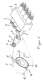
- a valve device is shown, which in Essentially from a cuboid housing 1 for one Valve block and of parallel side walls 2 each Housing 1 protruding solenoid valves 3 exists.
- the solenoid valves 3 are arranged in rows, the two Rows of opposing solenoid valves 3 have a common one Extend the extension level.
- valve unit In the housing 1 of the valve block are in a known manner Contain components that indicate the direction, size, or size Control the pressure of the volume flow of a liquid, which through and not shown openings of the valve block 1 is dissipated.
- the valve unit thus formed can can be used for example as a directional valve unit.
- the solenoid valves are used to actuate this valve unit 3, each essentially by a sliding Magnetic core receiving and from the side wall 2 protruding sleeve 4 and a slide-on sleeve 4 Solenoid 5 is formed.
- the sleeve 4 has a free end Thread so that after pushing on the solenoid 5 the same by actuating a union nut 6 to the Side wall 2 of the valve block housing 1 can be fixed.
- the electronic control unit For contacting the solenoid valve 3 or the solenoid 5 with an integrated in the housing 1 of the valve block, electronic control unit, not shown, the is arranged on an upper side of the valve block the solenoid 5 in a valve block 1 facing frontal area 7 on two contact elements 8 with not shown, arranged on the side wall 2 corresponding Contact elements can be electrically connected are.
- the electronic control unit can be inside of the housing 1 can also be positioned so that the in the side walls 2 bordered contact elements, the connections form the electronic control unit.
- the electronic control unit is adjacent to the valve block arranged within the housing 1, according to the present embodiments are electronic Control unit connects to an upper side of the valve block. So that the electrical connection path between the Contact elements 8 of the solenoid 5 and the connections the electronic control unit is as short as possible the contact elements 8 or the corresponding contact elements the side walls 2 in one to the top of the housing 1 near area arranged.
- the contact elements 8 formed as contact pins that in the as shots trained contact elements of the side walls 2 clamping are insertable.
- the contact pins 8 protrude from one front annular surface 10 of the solenoid 5 in the axial Direction down, going in one to an outer wall edge 11 of the magnet coil 5 near area. hereby becomes one oriented to the electronic control unit Position of the contact pins 8 guaranteed.
- the contact pins can also have a lateral surface 12 of the magnetic coil 5 angular in the radial direction protrude so that a direct connection with the electronic Control unit is guaranteed.
- the contact pins would be hook-shaped or zigzag-shaped in this case be trained.
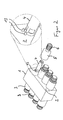
- FIG. 2 in contrast to the embodiment according to FIG. 1 reverse formation of the contact elements of the magnetic coil 5 on the one hand and the housing 1 on the other hand.
- Figure 2 clearly shows 2 pins from the side wall 13 protrude into the corresponding, not shown engage sleeve-shaped receptacles of the magnetic coil 5.
- This will make the same electrical and mechanical Connection of the solenoid 5 with the housing 1 causes as in the embodiment of Figure 1.
- Advantageous serves the sleeve 4 as a guide when putting on Magnetic coil 5 on the side wall, with the contact the corresponding contact elements of the solenoids 5 on the one hand and the housing 1 on the other hand a mechanical Connection is created, which is screwing on the Union nut 6 relieved.
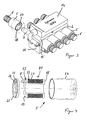
- the electronic control unit as a separate unit 14 formed on an upper side 15 of a valve block 16 is arranged to be placed and fixed.
- the contacting the magnetic coils 5 with connections of the electronic Unit 14 is carried out in the manner described above by contacting the annular surface 10 of the solenoids 5 with the Side walls 2 with the engagement of contact pins 17 in corresponding recordings of the valve block 16.
- There are more electrical connection means, not shown, for example Connector, between the valve block 16 and the electronic control unit 14 is provided so that a electrical connection between the solenoid 5 and the electronic control unit 14 is guaranteed.
- the magnet coil 5 has a hollow cylindrical winding support 18 on the one in the end regions has annular radial wall 19 to limit a Winding holder 20.
- a Winding wire 21 wound according to a conventional layer winding ends of the winding wire 21 each with inner ends 22 of the contact pins 8 are electrically connected are.
- the contact pins 8 in through bores 23 of a radial wall 19 so far inserted that the inner end 22 at an intended Position is positioned within the winding holder 20.
- the winding wire 21 becomes known Way around the winding carrier 18 or in the winding holder 20 wound up, using known connection techniques (Soldering etc.) one end of the winding wire 21 connected to the inner end 22 of the contact pin 8 becomes.
- the winding carrier 18 is in a cup-shaped Housing sleeve 24 used the winding carrier 18 covers the circumference.
- an annular plate 25 is provided, the circumferential one has corresponding seal 9 shown in Figure 1 and placed sealingly on an end face of the housing sleeve 24 becomes. So that the contact pins 8 protrude outwards, the annular plate 25 has corresponding openings 26 for the passage of the contact pins 8.
- the seals 9 are arranged as an O-ring on both ends of the solenoid 5.
- the contact elements 8 of the magnetic coil 5 corresponding contact elements of the valve block 1 also only via a cable harness with a not central plug unit shown to be connected.
- the Central plug-in unit can be on one end of the valve block 1 be arranged. Preferably those are from opposite Contact elements outgoing lines of a common reference potential, in particular the ground line, merged and then on a common line connected to the central plug-in unit.
- the harness is arranged within the valve block 1, so that a rational cable routing with complete shielding guaranteed is.
Landscapes
- Engineering & Computer Science (AREA)
- Physics & Mathematics (AREA)
- Fluid Mechanics (AREA)
- Mechanical Engineering (AREA)
- General Engineering & Computer Science (AREA)
- Electromagnetism (AREA)
- Power Engineering (AREA)
- Transportation (AREA)
- Magnetically Actuated Valves (AREA)
- Reciprocating, Oscillating Or Vibrating Motors (AREA)
- Burglar Alarm Systems (AREA)
- Vending Machines For Individual Products (AREA)
- Electromagnets (AREA)
Abstract
Description
- Figur 1
- eine perspektivische Darstellung eines Ventilblockes mit an gegenüberliegenden Seitenwänden angeordneten Magnetventilen, wobei Magnetspulen der Magnetventile an einer Stirnseite axial abragende Kontaktstifte aufweisen,
- Figur 2
- eine perspektivische Darstellung eines Ventilblockes mit an gegenüberliegenden parallelen Seitenwänden abragenden Magnetventilen, wobei von der Seitenwand des Ventilblockes Kontaktstifte abragen zur Kontaktierung-einer in einem Gehäuse des Ventilblockes integrierten elektronischen Steuereinheit mit der Magnetspule,
- Figur 3
- eine perspektivische Darstellung eines Ventilblockes mit an gegenüberliegenden Seitenwänden abragenden Magnetventilen, wobei auf einer Oberseite des Ventilblockes eine elektronische Steuereinheit als gesonderte Baueinheit befestigt angeordnet ist und
- Figur 4
- eine Explosionsdarstellung einer Magnetspule.
Claims (12)
- Vorrichtung zur Kontaktierung einer Stelleinheit mit elektrischen Anschlüssen eines Funktionsträgers, insbesondere eines hydraulischen Ventilblocks, wobei die Stelleinheit mit einer Magnetspule von dem Funktionsträger abragt, dadurch gekennzeichnet, dass in einem dem Funktionsträger (1) zugewandten stirnseitigen Bereich (7) der Stelleinheit (5) Kontaktelemente (8) derart angeordnet sind, dass die Kontaktelemente (8) mit korrespondierenden Kontaktelementen am Funktionsträger (1, 14) unmittelbar elektrisch verbindbar sind.
- Vorrichtung nach Anspruch 1, dadurch gekennzeichnet, dass die Kontaktelemente (8) der Stelleinheit (5) an einer dem Funktionsträger (1, 14) zugewandten Stirnseite (10) der Stelleinheit (5) angeordnet sind.
- Vorrichtung nach Anspruch 1 oder 2, dadurch gekennzeichnet, dass die Stelleinheit eine Magnetspule (5) umfasst und dass der Funktionsträger als Ventilblock (1) ausgebildet ist, wobei die Magnetspule (5) auf ein von Seitenwänden (2) des Ventilblocks (1) abragenden Rohrgestell (4) aufschiebbar und unter Anlage einer Ringfläche (10) an der Seitenwand (2) mit in der Seitenwand (2) eingefassten korrespondierenden Kontaktelementen verbindbar ist.
- Vorrichtung nach einem der Ansprüche 1 bis 3, dadurch gekennzeichnet, dass die in der Seitenwand (2) integrierten Kontaktelemente elektrische Anschlüsse für eine elektronische Steuereinheit bilden, mittels derer die in dem Ventilblock (1) angeordneten Ventile steuerbar sind.
- Vorrichtung nach einem der Ansprüche 1 bis 4, dadurch gekennzeichnet, dass die elektronische Steuereinheit in dem Gehäuse (1) des Ventilblockes integriert angeordnet ist.
- Vorrichtung nach einem der Ansprüche 1 bis 4, dadurch gekennzeichnet, dass die elektronische Steuereinheit als gesonderte Baueinheit (14) auf einer Oberseite (15) des Ventilblockes (16) aufsetzbar und festlegbar angeordnet ist.
- Vorrichtung nach einem der Ansprüche 1 bis 3, dadurch gekennzeichnet, dass die in der Seitenwand (2) des Funktionsträgers (1) angeordneten Kontaktelemente (8) mit einem Kabelstrang verbunden sind, der sich zwischen den Kontaktelementen des Funktionsträgers (1) und einer zentralen Steckeinheit des Funktionsträgers (1) erstreckt.
- Vorrichtung nach Anspruch 7, dadurch gekennzeichnet, dass die einem gemeinsamen Bezugspotential zugeordneten Kabel des Kabelstrangs ausgehend von den Kontaktelementen des Funktionsträgers (1) zusammengeführt zu der zentralen Steckeinheit geführt sind.
- Vorrichtung nach einem der Ansprüche 1 bis 8, dadurch gekennzeichnet, dass die Kontaktelemente (8) der Magnetspule (5) oder die in der Seitenwand (2) eingefassten Kontaktelemente als in axialer Richtung orientierte Kontaktstifte (8, 13) ausgebildet sind und dass die zu denselben korrespondierenden, in der Seitenwand (2) eingefassten Kontaktelemente bzw. die Kontaktelemente der Magnetspule (5) als Aufnahmen ausgebildet sind, in die die Kontaktstifte (8, 13) klemmend einsteckbar sind.
- Magnetspule, insbesondere zur Verwendung in einer Vorrichtung nach einem der Ansprüche 1 bis 9, mit einem hohlzylinderförmigen Wicklungsträger, der eine Wicklungsaufnahme aufweist zur Aufnahme eines Wicklungsdrahtes, wobei Enden des Wicklungsdrahtes mit von außen zugänglichen Kontaktstiften verbunden sind, dadurch gekennzeichnet, dass die Kontaktstifte (8) mit einem inneren Ende (22) in die Wicklungsaufnahme (20) eingreifen, wobei das innere Ende (22) mit dem Ende des Wicklungsdrahtes (21) elektrisch verbunden ist, und dass der Wicklungsträger (18) umfangsseitig durch eine passgenaue Gehäusehülse (24) umschlossen ist.
- Magnetspule nach Anspruch 10, dadurch gekennzeichnet, dass der Wicklungsträger (18) eine die Wicklungsaufnahme (20) begrenzende Radialwand (19) aufweist, die Durchgangsbohrungen (23) aufweist zur lagerichtigen Positionierung der Kontaktstifte (8) am Wicklungsträger (18).
- Magnetspule nach Anspruch 10 oder 11, dadurch gekennzeichnet, dass der in der Gehäusehülse (24) eingefasste Wicklungsträger (18) an einer offenen Stirnseite durch eine Kreisringplatte (25) abgedeckt ist, die zu den Kontaktelementen (8) korrespondierende Öffnungen (26) aufweist, und dass zwischen der Kreisringplatte (25) und der Gehäusehülse (25) eine kreisringförmige Dichtung (9) angeordnet ist.
Applications Claiming Priority (2)
| Application Number | Priority Date | Filing Date | Title |
|---|---|---|---|
| DE10063471A DE10063471A1 (de) | 2000-12-19 | 2000-12-19 | Kontaktierungsvorrichtung und eine Magnetspule |
| DE10063471 | 2000-12-19 |
Publications (2)
| Publication Number | Publication Date |
|---|---|
| EP1216904A1 true EP1216904A1 (de) | 2002-06-26 |
| EP1216904B1 EP1216904B1 (de) | 2010-09-08 |
Family
ID=7667914
Family Applications (1)
| Application Number | Title | Priority Date | Filing Date |
|---|---|---|---|
| EP01128870A Expired - Lifetime EP1216904B1 (de) | 2000-12-19 | 2001-12-05 | Kontaktierungsvorrichtung und eine Magnetspule |
Country Status (5)
| Country | Link |
|---|---|
| US (1) | US6840265B2 (de) |
| EP (1) | EP1216904B1 (de) |
| AT (1) | ATE480433T1 (de) |
| DE (2) | DE10063471A1 (de) |
| RU (1) | RU2276819C2 (de) |
Cited By (3)
| Publication number | Priority date | Publication date | Assignee | Title |
|---|---|---|---|---|
| DE102006053628A1 (de) * | 2006-11-14 | 2008-05-15 | Marco Systemanalyse Und Entwicklung Gmbh | Ventileinheit |
| DE102012219579A1 (de) * | 2012-10-25 | 2014-04-30 | Continental Teves Ag & Co. Ohg | Elektrohydraulische Druckregelvorrichtung für Kraftfahrzeugbremssysteme |
| EP3016116A1 (de) * | 2014-11-03 | 2016-05-04 | Roche Diagniostics GmbH | Leiterplattenanordnung, Spule für ein Laborprobenverteilungssystem, Laborprobenverteilungssystem und Laborautomatisierungssystem |
Families Citing this family (8)
| Publication number | Priority date | Publication date | Assignee | Title |
|---|---|---|---|---|
| DE102005028201C5 (de) * | 2005-05-19 | 2009-09-17 | Wilhelm Karmann Gmbh | Betätigungsaggregat |
| CN101506561B (zh) * | 2006-08-23 | 2012-04-18 | 株式会社堀场Stec | 组合式气体分配盘装置 |
| JP4968024B2 (ja) * | 2007-11-30 | 2012-07-04 | アイシン・エィ・ダブリュ株式会社 | バルブアッセンブリ |
| US20110180147A1 (en) * | 2010-01-28 | 2011-07-28 | Thermo Fisher Scientific Inc. | Method and apparatus for improved solenoid valves |
| DE102010020346A1 (de) * | 2010-05-12 | 2011-11-17 | Harting Electric Gmbh & Co. Kg | Elektrisches Kontaktelement |
| DE102013200419A1 (de) * | 2013-01-14 | 2014-07-31 | Robert Bosch Gmbh | Hydraulikmodul für ein Antiblockiersystem für ein Zweirad |
| JP2019151229A (ja) * | 2018-03-05 | 2019-09-12 | ロベルト・ボッシュ・ゲゼルシャフト・ミト・ベシュレンクテル・ハフツングRobert Bosch Gmbh | ブレーキ液圧制御装置 |
| RU2715377C9 (ru) * | 2019-09-20 | 2020-04-29 | Российская Федерация, от имени которой выступает Государственная корпорация по атомной энергии "Росатом" (Госкорпорация "Росатом") | Разъемный соединитель |
Citations (5)
| Publication number | Priority date | Publication date | Assignee | Title |
|---|---|---|---|---|
| US5326161A (en) * | 1990-11-17 | 1994-07-05 | Motorola, Inc. | Assembly and elastomeric seating member for providing a flexable seat for a member |
| WO1998040260A1 (en) * | 1997-03-11 | 1998-09-17 | Kelsey-Hayes Company | Sleeve and armature subassembly for control valves of vehicular braking systems and method of forming |
| US5941282A (en) * | 1996-10-25 | 1999-08-24 | Aisin Seiki Kabushiki Kaisha | Electromagnetic valve unit |
| EP0997363A2 (de) * | 1998-10-30 | 2000-05-03 | Kelsey Hayes Company | Zufuhrventil für eine hydraulische Steuereinheit eines Fahrzeugbremssystems |
| US6124775A (en) * | 1997-03-05 | 2000-09-26 | Kelsey-Hayes Company | Bobbinless solenoid coil |
Family Cites Families (23)
| Publication number | Priority date | Publication date | Assignee | Title |
|---|---|---|---|---|
| US3232312A (en) * | 1961-12-20 | 1966-02-01 | Parker Hannifin Corp | Solenoid operated valve assembly |
| US3717179A (en) * | 1971-04-29 | 1973-02-20 | Rex Chainbelt Inc | Solenoid operated valve |
| SU842996A1 (ru) * | 1979-08-30 | 1981-06-30 | Volovich Mark Ya | Катушка электромагнита и способ ее изго-ТОВлЕНи |
| US4308891A (en) * | 1980-03-31 | 1982-01-05 | Double A Products Co. | Terminal blocks and indicator for solenoid valves |
| SU892505A1 (ru) * | 1980-04-24 | 1981-12-23 | Предприятие П/Я А-3816 | Высоковольтный вакуумный переключатель |
| US4387739A (en) * | 1981-09-22 | 1983-06-14 | Schaming Edward J | Valve module for digital coolant control system |
| US4736177A (en) * | 1985-10-31 | 1988-04-05 | Automatic Switch Company | Solenoid actuator with electrical connection modules |
| JPH0627901Y2 (ja) * | 1987-07-03 | 1994-07-27 | 黒田精工株式会社 | 電磁弁装置 |
| DE3729216A1 (de) * | 1987-09-02 | 1989-03-16 | Teves Gmbh Alfred | Hydraulikaggregat |
| US4913189A (en) * | 1989-03-17 | 1990-04-03 | Colt Industries Inc. | Climate control system control module |
| DE8910805U1 (de) * | 1989-09-09 | 1991-01-10 | Robert Bosch Gmbh, 7000 Stuttgart | Elektrische Verbindungsvorrichtung |
| DE4004834C2 (de) * | 1990-02-16 | 1996-06-13 | Festo Kg | Ventilbaugruppe |
| JP2963253B2 (ja) * | 1991-10-07 | 1999-10-18 | 本田技研工業株式会社 | ソレノイドバルブの取付構造 |
| JPH06241342A (ja) * | 1993-02-19 | 1994-08-30 | Aisin Seiki Co Ltd | 電磁弁装置 |
| DE4306220A1 (de) * | 1993-02-27 | 1994-09-01 | Teves Gmbh Alfred | Verfahren zum Verschließen von Druckmittel führenden Kanälen in einem Gehäuse |
| DE4412664A1 (de) * | 1994-04-13 | 1995-10-19 | Bosch Gmbh Robert | Elektrohydraulische Druckeinstellvorrichtung, insbesondere für eine schlupfgeregelte Fahrzeugbremsanlage |
| DE29508389U1 (de) * | 1995-05-19 | 1995-07-20 | Siemens AG, 80333 München | Magnetspule zur Ventilsteuerung |
| JPH09126207A (ja) * | 1995-10-31 | 1997-05-13 | Aisin Seiki Co Ltd | 圧力制御装置 |
| US5845672A (en) * | 1996-12-10 | 1998-12-08 | General Motors Corporation | Solenoid coil positioning assembly |
| DE19718242A1 (de) * | 1997-04-30 | 1998-11-05 | Itt Mfg Enterprises Inc | Vorrichtung und Verfahren zur Kontaktierung von Spulen von Magnetventilen einer regelbaren Bremsanlage |
| DE19727414A1 (de) * | 1997-06-27 | 1999-01-07 | Bosch Gmbh Robert | Verfahren zur Herstellung einer Magnetspule für ein Ventil und Ventil mit einer Magnetspule |
| DE19848039A1 (de) * | 1998-10-17 | 2000-04-20 | Bosch Gmbh Robert | Anordnung zur Kontaktierung eines einen elektrischen Anschluß aufweisenden Bauteils mit einer elektrischen Schaltung |
| DE19922425C1 (de) * | 1999-05-14 | 2000-10-19 | Siemens Ag | Elektromechanischer Stellantrieb und seine Montage z.B. als Gaswechselventil in den Zylinderkopf einer Brennkraftmaschine |
-
2000
- 2000-12-19 DE DE10063471A patent/DE10063471A1/de not_active Withdrawn
-
2001
- 2001-12-05 AT AT01128870T patent/ATE480433T1/de not_active IP Right Cessation
- 2001-12-05 DE DE50115618T patent/DE50115618D1/de not_active Expired - Lifetime
- 2001-12-05 EP EP01128870A patent/EP1216904B1/de not_active Expired - Lifetime
- 2001-12-14 RU RU2001133537/09A patent/RU2276819C2/ru not_active IP Right Cessation
- 2001-12-18 US US10/023,607 patent/US6840265B2/en not_active Expired - Fee Related
Patent Citations (5)
| Publication number | Priority date | Publication date | Assignee | Title |
|---|---|---|---|---|
| US5326161A (en) * | 1990-11-17 | 1994-07-05 | Motorola, Inc. | Assembly and elastomeric seating member for providing a flexable seat for a member |
| US5941282A (en) * | 1996-10-25 | 1999-08-24 | Aisin Seiki Kabushiki Kaisha | Electromagnetic valve unit |
| US6124775A (en) * | 1997-03-05 | 2000-09-26 | Kelsey-Hayes Company | Bobbinless solenoid coil |
| WO1998040260A1 (en) * | 1997-03-11 | 1998-09-17 | Kelsey-Hayes Company | Sleeve and armature subassembly for control valves of vehicular braking systems and method of forming |
| EP0997363A2 (de) * | 1998-10-30 | 2000-05-03 | Kelsey Hayes Company | Zufuhrventil für eine hydraulische Steuereinheit eines Fahrzeugbremssystems |
Cited By (4)
| Publication number | Priority date | Publication date | Assignee | Title |
|---|---|---|---|---|
| DE102006053628A1 (de) * | 2006-11-14 | 2008-05-15 | Marco Systemanalyse Und Entwicklung Gmbh | Ventileinheit |
| DE102012219579A1 (de) * | 2012-10-25 | 2014-04-30 | Continental Teves Ag & Co. Ohg | Elektrohydraulische Druckregelvorrichtung für Kraftfahrzeugbremssysteme |
| EP3016116A1 (de) * | 2014-11-03 | 2016-05-04 | Roche Diagniostics GmbH | Leiterplattenanordnung, Spule für ein Laborprobenverteilungssystem, Laborprobenverteilungssystem und Laborautomatisierungssystem |
| WO2016071210A1 (en) * | 2014-11-03 | 2016-05-12 | Roche Diagnostics Gmbh | Laboratory sample distribution system and laboratory automation system |
Also Published As
| Publication number | Publication date |
|---|---|
| EP1216904B1 (de) | 2010-09-08 |
| RU2276819C2 (ru) | 2006-05-20 |
| US20020096938A1 (en) | 2002-07-25 |
| ATE480433T1 (de) | 2010-09-15 |
| DE50115618D1 (de) | 2010-10-21 |
| US6840265B2 (en) | 2005-01-11 |
| DE10063471A1 (de) | 2002-06-20 |
Similar Documents
| Publication | Publication Date | Title |
|---|---|---|
| DE10338377A1 (de) | Magnetventil mit Anschlusskasten | |
| DE10107239A1 (de) | Steuereinrichtung für Druckmittel | |
| EP0655609B1 (de) | Gehäuse für Messwertgeber | |
| DE602004008842T2 (de) | Steckverbindungsgerät für kompakte Stellmotoren | |
| EP1216904B1 (de) | Kontaktierungsvorrichtung und eine Magnetspule | |
| DE102006030412B4 (de) | Elektromagnetventil | |
| EP2388555B1 (de) | Induktiver Sensor und Verfahren zu dessen Montage | |
| WO2001091244A1 (de) | Druckausgeglichener steckverbinder | |
| DE102018113130A1 (de) | Elektrikverbindungsstruktur und Herstellverfahren hierfür | |
| DE2337843C2 (de) | Magnet für elektromagnetisch betätigte Ventile | |
| WO1997036773A1 (de) | Reglereinheit | |
| DE19707587B4 (de) | Elektromagnetische Stelleinrichtung | |
| EP0446201B1 (de) | Kraftstoff-einspritzdüse für brennkraftmaschinen | |
| DE3723223C2 (de) | ||
| EP0154001B1 (de) | Kupplungsteil zum druckdichten Befestigen einer Druckmittelleitung an einem Druckmittelanschluss | |
| DE3430834A1 (de) | Mehrstufenanschlusssystem unter verwendung auslenkbarer schaltbarer sondenbaugruppen | |
| EP0068339A1 (de) | Kraftstoff-Einspritzdüse für Brennkraftmaschinen | |
| CH648642A5 (de) | Stelleinrichtung eines hydraulischen, elektronisch steuerbaren proportionalventils. | |
| EP0278227B1 (de) | Stelleinrichtung für ein hydraulisches, elektrisch steuerbares Proportionalventil | |
| DE10138728A1 (de) | Kupplungselement zur Anbringung an einer geschirmten elektrischen Leitung und Verfahren zu seiner Anbringung an einer Leitung | |
| DE3433025C2 (de) | Kabelanschlußvorrichtung | |
| DE10119939A1 (de) | Magnetspulenanordnung | |
| DE3605388A1 (de) | Elektrohydraulische schaltvorrichtung | |
| DE3637350C2 (de) | ||
| DE19737721A1 (de) | Vorrichtung zur programmgesteuerten Ausführung einer Funktion |
Legal Events
| Date | Code | Title | Description |
|---|---|---|---|
| PUAI | Public reference made under article 153(3) epc to a published international application that has entered the european phase |
Free format text: ORIGINAL CODE: 0009012 |
|
| AK | Designated contracting states |
Kind code of ref document: A1 Designated state(s): AT BE CH CY DE DK ES FI FR GB GR IE IT LI LU MC NL PT SE TR |
|
| AX | Request for extension of the european patent |
Free format text: AL;LT;LV;MK;RO;SI |
|
| AKX | Designation fees paid | ||
| 17P | Request for examination filed |
Effective date: 20021227 |
|
| RBV | Designated contracting states (corrected) |
Designated state(s): AT BE CH CY DE DK ES FI FR GB GR IE IT LI LU MC NL PT SE TR |
|
| REG | Reference to a national code |
Ref country code: DE Ref legal event code: 8566 |
|
| 17Q | First examination report despatched |
Effective date: 20040204 |
|
| GRAP | Despatch of communication of intention to grant a patent |
Free format text: ORIGINAL CODE: EPIDOSNIGR1 |
|
| GRAS | Grant fee paid |
Free format text: ORIGINAL CODE: EPIDOSNIGR3 |
|
| GRAA | (expected) grant |
Free format text: ORIGINAL CODE: 0009210 |
|
| AK | Designated contracting states |
Kind code of ref document: B1 Designated state(s): AT BE CH CY DE DK ES FI FR GB GR IE IT LI LU MC NL PT SE TR |
|
| REG | Reference to a national code |
Ref country code: GB Ref legal event code: FG4D Free format text: NOT ENGLISH |
|
| REG | Reference to a national code |
Ref country code: CH Ref legal event code: EP |
|
| REG | Reference to a national code |
Ref country code: IE Ref legal event code: FG4D Free format text: LANGUAGE OF EP DOCUMENT: GERMAN |
|
| REF | Corresponds to: |
Ref document number: 50115618 Country of ref document: DE Date of ref document: 20101021 Kind code of ref document: P |
|
| REG | Reference to a national code |
Ref country code: NL Ref legal event code: VDEP Effective date: 20100908 |
|
| PG25 | Lapsed in a contracting state [announced via postgrant information from national office to epo] |
Ref country code: FI Free format text: LAPSE BECAUSE OF FAILURE TO SUBMIT A TRANSLATION OF THE DESCRIPTION OR TO PAY THE FEE WITHIN THE PRESCRIBED TIME-LIMIT Effective date: 20100908 |
|
| PG25 | Lapsed in a contracting state [announced via postgrant information from national office to epo] |
Ref country code: CY Free format text: LAPSE BECAUSE OF FAILURE TO SUBMIT A TRANSLATION OF THE DESCRIPTION OR TO PAY THE FEE WITHIN THE PRESCRIBED TIME-LIMIT Effective date: 20100908 |
|
| REG | Reference to a national code |
Ref country code: IE Ref legal event code: FD4D |
|
| PG25 | Lapsed in a contracting state [announced via postgrant information from national office to epo] |
Ref country code: NL Free format text: LAPSE BECAUSE OF FAILURE TO SUBMIT A TRANSLATION OF THE DESCRIPTION OR TO PAY THE FEE WITHIN THE PRESCRIBED TIME-LIMIT Effective date: 20100908 Ref country code: GR Free format text: LAPSE BECAUSE OF FAILURE TO SUBMIT A TRANSLATION OF THE DESCRIPTION OR TO PAY THE FEE WITHIN THE PRESCRIBED TIME-LIMIT Effective date: 20101209 Ref country code: SE Free format text: LAPSE BECAUSE OF FAILURE TO SUBMIT A TRANSLATION OF THE DESCRIPTION OR TO PAY THE FEE WITHIN THE PRESCRIBED TIME-LIMIT Effective date: 20100908 |
|
| PG25 | Lapsed in a contracting state [announced via postgrant information from national office to epo] |
Ref country code: IE Free format text: LAPSE BECAUSE OF FAILURE TO SUBMIT A TRANSLATION OF THE DESCRIPTION OR TO PAY THE FEE WITHIN THE PRESCRIBED TIME-LIMIT Effective date: 20100908 |
|
| PG25 | Lapsed in a contracting state [announced via postgrant information from national office to epo] |
Ref country code: PT Free format text: LAPSE BECAUSE OF FAILURE TO SUBMIT A TRANSLATION OF THE DESCRIPTION OR TO PAY THE FEE WITHIN THE PRESCRIBED TIME-LIMIT Effective date: 20110110 |
|
| PG25 | Lapsed in a contracting state [announced via postgrant information from national office to epo] |
Ref country code: ES Free format text: LAPSE BECAUSE OF FAILURE TO SUBMIT A TRANSLATION OF THE DESCRIPTION OR TO PAY THE FEE WITHIN THE PRESCRIBED TIME-LIMIT Effective date: 20101219 |
|
| PLBE | No opposition filed within time limit |
Free format text: ORIGINAL CODE: 0009261 |
|
| STAA | Information on the status of an ep patent application or granted ep patent |
Free format text: STATUS: NO OPPOSITION FILED WITHIN TIME LIMIT |
|
| PG25 | Lapsed in a contracting state [announced via postgrant information from national office to epo] |
Ref country code: MC Free format text: LAPSE BECAUSE OF NON-PAYMENT OF DUE FEES Effective date: 20101231 |
|
| REG | Reference to a national code |
Ref country code: CH Ref legal event code: PL |
|
| 26N | No opposition filed |
Effective date: 20110609 |
|
| GBPC | Gb: european patent ceased through non-payment of renewal fee |
Effective date: 20101208 |
|
| PG25 | Lapsed in a contracting state [announced via postgrant information from national office to epo] |
Ref country code: DK Free format text: LAPSE BECAUSE OF FAILURE TO SUBMIT A TRANSLATION OF THE DESCRIPTION OR TO PAY THE FEE WITHIN THE PRESCRIBED TIME-LIMIT Effective date: 20100908 |
|
| REG | Reference to a national code |
Ref country code: DE Ref legal event code: R097 Ref document number: 50115618 Country of ref document: DE Effective date: 20110609 |
|
| PG25 | Lapsed in a contracting state [announced via postgrant information from national office to epo] |
Ref country code: LI Free format text: LAPSE BECAUSE OF NON-PAYMENT OF DUE FEES Effective date: 20101231 Ref country code: CH Free format text: LAPSE BECAUSE OF NON-PAYMENT OF DUE FEES Effective date: 20101231 |
|
| PG25 | Lapsed in a contracting state [announced via postgrant information from national office to epo] |
Ref country code: GB Free format text: LAPSE BECAUSE OF NON-PAYMENT OF DUE FEES Effective date: 20101208 |
|
| PG25 | Lapsed in a contracting state [announced via postgrant information from national office to epo] |
Ref country code: AT Free format text: LAPSE BECAUSE OF NON-PAYMENT OF DUE FEES Effective date: 20101205 |
|
| REG | Reference to a national code |
Ref country code: AT Ref legal event code: MM01 Ref document number: 480433 Country of ref document: AT Kind code of ref document: T Effective date: 20101205 |
|
| PG25 | Lapsed in a contracting state [announced via postgrant information from national office to epo] |
Ref country code: LU Free format text: LAPSE BECAUSE OF NON-PAYMENT OF DUE FEES Effective date: 20101205 |
|
| PG25 | Lapsed in a contracting state [announced via postgrant information from national office to epo] |
Ref country code: TR Free format text: LAPSE BECAUSE OF FAILURE TO SUBMIT A TRANSLATION OF THE DESCRIPTION OR TO PAY THE FEE WITHIN THE PRESCRIBED TIME-LIMIT Effective date: 20100908 |
|
| REG | Reference to a national code |
Ref country code: FR Ref legal event code: PLFP Year of fee payment: 15 |
|
| PGFP | Annual fee paid to national office [announced via postgrant information from national office to epo] |
Ref country code: DE Payment date: 20151104 Year of fee payment: 15 |
|
| PGFP | Annual fee paid to national office [announced via postgrant information from national office to epo] |
Ref country code: FR Payment date: 20151221 Year of fee payment: 15 Ref country code: BE Payment date: 20151221 Year of fee payment: 15 |
|
| PGFP | Annual fee paid to national office [announced via postgrant information from national office to epo] |
Ref country code: IT Payment date: 20151228 Year of fee payment: 15 |
|
| PG25 | Lapsed in a contracting state [announced via postgrant information from national office to epo] |
Ref country code: BE Free format text: LAPSE BECAUSE OF NON-PAYMENT OF DUE FEES Effective date: 20161231 |
|
| REG | Reference to a national code |
Ref country code: DE Ref legal event code: R119 Ref document number: 50115618 Country of ref document: DE |
|
| REG | Reference to a national code |
Ref country code: FR Ref legal event code: ST Effective date: 20170831 |
|
| PG25 | Lapsed in a contracting state [announced via postgrant information from national office to epo] |
Ref country code: IT Free format text: LAPSE BECAUSE OF NON-PAYMENT OF DUE FEES Effective date: 20161205 Ref country code: FR Free format text: LAPSE BECAUSE OF NON-PAYMENT OF DUE FEES Effective date: 20170102 |
|
| PG25 | Lapsed in a contracting state [announced via postgrant information from national office to epo] |
Ref country code: DE Free format text: LAPSE BECAUSE OF NON-PAYMENT OF DUE FEES Effective date: 20170701 |
|
| REG | Reference to a national code |
Ref country code: BE Ref legal event code: MM Effective date: 20161231 |