EP0655855A2 - Balayeur cunéiforme utilisant des matrices de capteurs bidimensionelles - Google Patents
Balayeur cunéiforme utilisant des matrices de capteurs bidimensionelles Download PDFInfo
- Publication number
- EP0655855A2 EP0655855A2 EP94308748A EP94308748A EP0655855A2 EP 0655855 A2 EP0655855 A2 EP 0655855A2 EP 94308748 A EP94308748 A EP 94308748A EP 94308748 A EP94308748 A EP 94308748A EP 0655855 A2 EP0655855 A2 EP 0655855A2
- Authority
- EP
- European Patent Office
- Prior art keywords
- detector
- scanner
- detectors
- pages
- book
- Prior art date
- Legal status (The legal status is an assumption and is not a legal conclusion. Google has not performed a legal analysis and makes no representation as to the accuracy of the status listed.)
- Granted
Links
Images


Classifications
-
- H—ELECTRICITY
- H04—ELECTRIC COMMUNICATION TECHNIQUE
- H04N—PICTORIAL COMMUNICATION, e.g. TELEVISION
- H04N1/00—Scanning, transmission or reproduction of documents or the like, e.g. facsimile transmission; Details thereof
- H04N1/024—Details of scanning heads ; Means for illuminating the original
- H04N1/028—Details of scanning heads ; Means for illuminating the original for picture information pick-up
- H04N1/02815—Means for illuminating the original, not specific to a particular type of pick-up head
- H04N1/02845—Means for illuminating the original, not specific to a particular type of pick-up head using an elongated light source, e.g. tubular lamp, LED array
- H04N1/0285—Means for illuminating the original, not specific to a particular type of pick-up head using an elongated light source, e.g. tubular lamp, LED array in combination with at least one reflector which is in fixed relation to the light source
-
- H—ELECTRICITY
- H04—ELECTRIC COMMUNICATION TECHNIQUE
- H04N—PICTORIAL COMMUNICATION, e.g. TELEVISION
- H04N1/00—Scanning, transmission or reproduction of documents or the like, e.g. facsimile transmission; Details thereof
- H04N1/024—Details of scanning heads ; Means for illuminating the original
- H04N1/028—Details of scanning heads ; Means for illuminating the original for picture information pick-up
- H04N1/02815—Means for illuminating the original, not specific to a particular type of pick-up head
-
- H—ELECTRICITY
- H04—ELECTRIC COMMUNICATION TECHNIQUE
- H04N—PICTORIAL COMMUNICATION, e.g. TELEVISION
- H04N1/00—Scanning, transmission or reproduction of documents or the like, e.g. facsimile transmission; Details thereof
- H04N1/024—Details of scanning heads ; Means for illuminating the original
- H04N1/028—Details of scanning heads ; Means for illuminating the original for picture information pick-up
- H04N1/02815—Means for illuminating the original, not specific to a particular type of pick-up head
- H04N1/02845—Means for illuminating the original, not specific to a particular type of pick-up head using an elongated light source, e.g. tubular lamp, LED array
- H04N1/02855—Means for illuminating the original, not specific to a particular type of pick-up head using an elongated light source, e.g. tubular lamp, LED array in combination with a light guide, e.g. optical fibre, glass plate
-
- H—ELECTRICITY
- H04—ELECTRIC COMMUNICATION TECHNIQUE
- H04N—PICTORIAL COMMUNICATION, e.g. TELEVISION
- H04N1/00—Scanning, transmission or reproduction of documents or the like, e.g. facsimile transmission; Details thereof
- H04N1/024—Details of scanning heads ; Means for illuminating the original
- H04N1/028—Details of scanning heads ; Means for illuminating the original for picture information pick-up
- H04N1/02815—Means for illuminating the original, not specific to a particular type of pick-up head
- H04N1/02885—Means for compensating spatially uneven illumination, e.g. an aperture arrangement
- H04N1/0289—Light diffusing elements, e.g. plates or filters
-
- H—ELECTRICITY
- H04—ELECTRIC COMMUNICATION TECHNIQUE
- H04N—PICTORIAL COMMUNICATION, e.g. TELEVISION
- H04N1/00—Scanning, transmission or reproduction of documents or the like, e.g. facsimile transmission; Details thereof
- H04N1/04—Scanning arrangements, i.e. arrangements for the displacement of active reading or reproducing elements relative to the original or reproducing medium, or vice versa
- H04N1/10—Scanning arrangements, i.e. arrangements for the displacement of active reading or reproducing elements relative to the original or reproducing medium, or vice versa using flat picture-bearing surfaces
-
- H—ELECTRICITY
- H04—ELECTRIC COMMUNICATION TECHNIQUE
- H04N—PICTORIAL COMMUNICATION, e.g. TELEVISION
- H04N1/00—Scanning, transmission or reproduction of documents or the like, e.g. facsimile transmission; Details thereof
- H04N1/04—Scanning arrangements, i.e. arrangements for the displacement of active reading or reproducing elements relative to the original or reproducing medium, or vice versa
- H04N1/19—Scanning arrangements, i.e. arrangements for the displacement of active reading or reproducing elements relative to the original or reproducing medium, or vice versa using multi-element arrays
- H04N1/195—Scanning arrangements, i.e. arrangements for the displacement of active reading or reproducing elements relative to the original or reproducing medium, or vice versa using multi-element arrays the array comprising a two-dimensional [2D] array
-
- H—ELECTRICITY
- H10—SEMICONDUCTOR DEVICES; ELECTRIC SOLID-STATE DEVICES NOT OTHERWISE PROVIDED FOR
- H10F—INORGANIC SEMICONDUCTOR DEVICES SENSITIVE TO INFRARED RADIATION, LIGHT, ELECTROMAGNETIC RADIATION OF SHORTER WAVELENGTH OR CORPUSCULAR RADIATION
- H10F39/00—Integrated devices, or assemblies of multiple devices, comprising at least one element covered by group H10F30/00, e.g. radiation detectors comprising photodiode arrays
- H10F39/10—Integrated devices
- H10F39/12—Image sensors
- H10F39/18—Complementary metal-oxide-semiconductor [CMOS] image sensors; Photodiode array image sensors
-
- H—ELECTRICITY
- H04—ELECTRIC COMMUNICATION TECHNIQUE
- H04N—PICTORIAL COMMUNICATION, e.g. TELEVISION
- H04N2201/00—Indexing scheme relating to scanning, transmission or reproduction of documents or the like, and to details thereof
- H04N2201/04—Scanning arrangements
- H04N2201/0402—Arrangements not specific to a particular one of the scanning methods covered by groups H04N1/04 - H04N1/207
- H04N2201/0434—Arrangements not specific to a particular one of the scanning methods covered by groups H04N1/04 - H04N1/207 specially adapted for scanning pages of a book
Definitions
- the present invention relates in general to scanners that simultaneously scan both pages of an open book without undue stress on the binding; and, in particular, to wedge scanners that employ two-dimensional sensing arrays.
- a light/lens copier works by moving a scanning bar across the entirety of a page.
- the bar illuminates a portion of the page and its image is reflected and focused by an optical system of lens and mirrors to an image capturing device, such as photoreceptor.
- the image of the page is scanned line by line until the scanning bar has moved down the entire length of the page - usually by a system of wheels and pulleys.
- Agarwal discloses the use of two platens that are joined together to form a "wedge" shape that allows the spine of the book to rest upon the corner of the wedge while the two opposite pages contact the surfaces of each respective platen. It is the shape of the wedge that reduces the amount of stress to the spine by allowing copies to be made of opposing pages without forcing the spine to be stretched beyond the angle defined by the wedge.
- An exposure lamp is disposed adjacent to the corner of the wedge to illuminate both pages for reproduction.
- Opposing book pages are scanned in Agarwal's system by moving the exposure lamp first down the entirety of one opposing page and then down the other opposing page.
- Agarwal and Pkater require moving parts to create opposing page images.
- Agarwal requires a moving exposure lamp that creates reproductions in the traditional light/lens method.
- Pkater (DE-A-35 45 404) has an arrangement of moving mirrors that create simultaneous virtual images; but does not disclose a means for capturing these images onto an intermediate substrate. The motion of these mechanical parts represent the majority of the time spent in scanning opposing book pages. It is thus desirable to scan opposing pages simultaneously without the use of moving mechanical parts.
- detectors comprise an array of thin film transistors and sensors that function as pixel element detectors. These thin film elements are generally constructed over a translucent substrate such as glass, forming a two dimensional detecting surface. Such thin film arrays are disclosed in US-A-5,017,989 and in US-A-5,079,426.
- Antonuk et al discloses an array structure that captures an images across all its pixel elements simultaneously. The image information is then read out by sequentially addressing each pixel. The exact structure and operation of the detector is described in greater detail in the above-mentioned patent and in context with the present invention below.
- the present invention provides a scanner for capturing the image of pages in a book, said scanner comprising: a first and a second 2-dimensional detector, each detector having a surface, a first edge and a second edge opposite said first edge, said detectors coupled at said first edges such that said surfaces are disposed in a substantial wedge shape; a light source for illuminating the opposing pages through said detector; and read-out circuitry connected to said detector for obtaining image data collected by said detector.
- opposite edges of the 2-D detector arrays are housed in a base portion.
- the base portion additionally supports backlighting to provide the necessary illumination of the book pages and the read-out electronics which output the image data stored in the detectors to other processing units that may use such data.
- One advantage of the present invention is that it provides a way to copy book pages quickly without undue stress to the binding of the book.
- Another advantage of the present invention is speed.
- the present invention does not use moving, mechanical parts.
- the speed of the present wedge scanner is generally faster than mechanisms employing such mechanical parts.
- Another advantage of the present invention is quietness.
- the present invention does not have the attendant noise typically generated by moving mechanical parts.
- the present invention is ideally suited to an environment where the quiet scanning of books is a major consideration, such as a library.
- the present invention is constructed from electronic components which generally have a greater longevity than moving mechanical parts.
- the wedge scanner could be used as an image capturing front-end.
- the data output from the wedge could then be used by any other processing unit that can use image data.
- the image data could be supplied to a copier, fax, or the like.
- OCR optical character recognition
- speech processing software the image data may be used to read books to the blind.
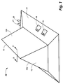
- Wedge scanner 10 comprises two 2-dimensional detector arrays 12a and 12b that are rigidly attached at a common edge 11.
- the detector arrays are comparatively thin sheets of substrate that project downward to form the "wedge" shape of the scanner.
- Translucent blocks made of light diffusing material, such as plexiglass, are placed within the wedge at 13 to provide diffuse lighting for proper illumination of the image page through the detector arrays.
- Detectors 12a and 12b are supported upon base 14 which houses both the backlighting necessary to illuminate opposing book pages as well as necessary electronics to address and read out the image data captured by the detectors.
- Switch mechanisms 16 and 18 are provided on the housing to give users control of backlighting and scanning respectively. These functions could, alternatively, be provided by a single control switch. Lines 20 and 21 connect with base 14 to supply the scanner with power and to output image data, respectively. It will be appreciated that the present invention is not limited by the particular design of the first presently preferred embodiment provided in Figure 1. In fact, any wedge-shaped scanner design comprising two 2-dimensional detector arrays providing a similar level of functionality is encompassed by the present invention.
- Figure 3 depicts the wedge scanner 10 in use.
- the spine of book 30 is shown resting on the edge 11 of the wedge.
- Opposing pages 32 and 34 lie adjacent each detector 12a and 12b, for being scanned.
- the pages to be scanned should ideally be contacting the surface of the detectors, or in reasonably close proximity, to produce a usable image.
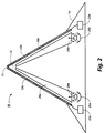
- a side sectional view of the first presently preferred embodiment is presented in Figure 2.
- Lights 24a and 24b are disposed inside base 14 to provide the necessary backlighting of the book pages to be copied. Lights 24a and 24b are controlled by the user via switch 16 (not shown in Figure 2). The light emanating from the lights is reflected by concave mirrors 25a and 25b respectively into the bottom surface of translucent blocks 26a and 26b.
- the translucent material could be plexiglass or any like material that diffuses light sufficiently. Diffuse lighting affords better imaging with the thin film transistor and sensor structures that are used in the presently preferred embodiments.
- the surface of the translucent blocks remote from the detectors might also have a mirrored coating to increase the illumination on the image page.
- a standard backlighting arrangement used in current liquid crystal displays delivers reasonably diffused lighting for the purposes of the present invention.
- Read-out electronics 22a and 22b are coupled to detectors 12a and 12b respectively. As will be discussed in greater detail below, the read-out electronics have both address and data-receive logics sufficient to address and read-out image data from individual pixels. As shown in Figure 2, there are two separate read-out electronics - one for each individual detector. In an alternative embodiment, however, the two array detectors could be electrically coupled so that the two detectors are in actuality one addressable surface. In such a case, only one set of address logics would be needed for the scanner. This implementation will be discussed in greater detail below.
- Figure 4 is a side sectional view of a typical pixel element used on the presently preferred array detector.
- Figure 5 is a cut-away, perspective view of the pixel element of Figure 4. It will be appreciated, however, that the present invention should not be limited to the choice of the presently preferred detector. In fact, any non-mechanical detector that captures an image by substantial contact with a page is suitable for the purposes of the present invention.
- a single pixel element comprises a sensor 50 electrically coupled to a thin film transistor 44.
- Sensor 50 is constructed atop a transparent substrate 41 made of glass or some other suitable material.
- the first layer of sensor 50 is an opaque conductive layer 52.
- Conductive layer 52 serves two purposes: first, it prevents light rays 39 from directly passing through sensor 50 and, second, it provides electrical connection to transistor 44.
- Heavily doped N-type a-Si:H layer 54 (approximately 400 ⁇ thick), intrinsic a-Si:H layer 56 (ranging from a few thousand Angstroms to several microns thick), and a heavily doped P-type a-Si:H layer 58 (approximately 100 ⁇ thick) sit on top of the conductive layer 52 and form a p-i-n photodiode.
- An upper electrode 60 sits atop layer 58 and connects to biasing line 61.
- Upper electrode 60 is made of a transparent material to allow the reflected light 40 to pass through to the photodiode.
- a final protective, transparent layer 42 (approximately 50 ⁇ m thick) covers the structure and provides the resting surface for book page 32.
- the construction and structure of both sensor 50 and thin film transistor 44 is further disclosed in US-A-5,079,426.
- sensor 50 stores information about that portion of the image that are immediately adjacent to it.
- Light rays 39 emanating from backlight 24a and 24b is transmitted through the transparent substrate 41 All direct rays to sensor 50 are stopped by the opaque conductive layer 52.
- rays 39 are transmitted in the gaps between adjacent sensors 50.
- Rays 39 eventually reach page 32 and reflect back (as reflected rays 40) towards the detector.
- the amount of reflected light 40 reaching sensor 50 is dependent upon the proximate surface characteristics of the page 32. More rays are reflected back into the sensor 50 if the page surface proximate to the sensor is predominately "white”. Likewise, if the page surface proximate to sensor 50 is "black", less rays will be reflected back towards the sensor.
- Individual pixel sizes in the presently preferred embodiment can be either 127 ⁇ m square (for 200 spi coverage) or 85 ⁇ m square (for 300 spi).
- the sensor size should be small enough to fit the pixel while leaving a sufficient gap for light to transmit through to the page.
- the "fill fraction” is defined as the fraction of the pixel area used by the sensor. A fill fraction in the range of 25 to 70% is suitable for adequate page lighting.
- FIG. 6 is a simple schematic of the array of sensors and transistors coupled to the read-out electronics.
- Each transistor 44 is connected to a pair of lines, address line 62 and data-receive line 64.
- Each address line 62 connects a plurality of transistors 44 via their gates in a columnar arrangement.
- the drain of each transistor is connected in row fashion to a data-receive line 64 which is in turn connected to the input terminals of a data receiving matrix 74.
- Address line driver 72 and data receiving matrix 74 enable the flow and capture of image data from the sensors respectively. Both the address line driver and the data receiving matrix must be synchronized in order that meaningful data may be retrieved from the array of detectors. This synchronization may be accomplished by inputting a clock signal to each of address line driver 72 and data receiver matrix 74 via line CLK. It will be appreciated that the actual logical design of both the address line driver and the data receive matrix are well known to those skilled in the art of circuit design.
- the image data is stored in the array as an electric charge in each of the sensors 50 until it is "read out”.
- the charges in these sensors are read out a column at a time and stored in the data receiver matrix 74.
- the process of reading out starts with a clock signal that induces address line driver 72 to enable a single address line 62.
- the gates of the transistors 44 that are coupled to that address line thereby become enabled and the stored charge in sensor 60 is allowed to flow to the data receiver matrix 74 via data-receive line 64.
- a column of pixel data is thus captured. This process continues until the entire array is read out, column by column.
- FIG 7 shows a second preferred embodiment of the wedge scanner.
- Scanner 80 is constructed so that the common edge 11 of the two detectors 12a and 12b is rotatably coupled by a hinge 82 or the like.
- the two detectors, together with their respective translucent blocks 26a and 26b, may rotate in the direction of arrows 84a and 84b respectively.
- suitable modifications can be made to the base (not shown in Figure 7) to support scanner 80 and are well known to one skilled in the art.
- This second embodiment is desirable because different books have different mechanical strengths in the spine and different weights of paper for their pages.
- the wedge of the second embodiment may vary its angle to optimize the mechanical interaction with the book to improve the physical contact of the pages with the detector surfaces.
- Figures 8A and 8B depict two implementations of a single scanning surface.
- Figure 8A shows detectors 12a and 12b connected to interconnect circuits 92a and 92b via a flexible connector 90.
- the circuits 92a and 92b may further connect to a processor or other logic circuits (not shown) to provide the logical mapping of the two scanning surfaces to a single surface.
- the two circuits could themselves be connected by another flexible connector (not shown).
- the flexible connector 90 may be any electrical material having sufficient flexibility (e.g. polymide) to withstand repeated bendings, as would be the case with the second preferred embodiment detailed in Figure 7.
- the connector could be mated to the detector or the circuit either by soldering, anisotropic adhesive, or the like.
- a second implementation for creating one effective scanning surface is merely to connect the two scanning surfaces 12a and 12b together with flexible connector 94.
- Flexible connectors 90 or 94 would connect a single pairs of corresponding address or data-receive lines on the detectors 12a and 12b.
- the grid lines on the detector surface that cross vertically from one detector to another would be electrically extended to one set of grid lines. Suitable modifications to the read out electronics to treat the two surfaces as one is well known to those skilled in circuit design.
- the present invention is a novel wedge scanner that copies opposing book pages without the use of moving, mechanical parts.
- the current application discloses a presently preferred 2-dimensionsal array constructed of thin film transistors and sensors, it should be appreciated that the present invention envisions and encompasses the use of any other two-dimensional array detectors.
Landscapes
- Engineering & Computer Science (AREA)
- Multimedia (AREA)
- Signal Processing (AREA)
- Facsimile Scanning Arrangements (AREA)
- Image Input (AREA)
Applications Claiming Priority (2)
| Application Number | Priority Date | Filing Date | Title |
|---|---|---|---|
| US08/158,676 US5359207A (en) | 1993-11-29 | 1993-11-29 | Wedge scanner utilizing two dimensional sensing arrays |
| US158676 | 1993-11-29 |
Publications (3)
| Publication Number | Publication Date |
|---|---|
| EP0655855A2 true EP0655855A2 (fr) | 1995-05-31 |
| EP0655855A3 EP0655855A3 (fr) | 1996-01-17 |
| EP0655855B1 EP0655855B1 (fr) | 2000-03-01 |
Family
ID=22569206
Family Applications (1)
| Application Number | Title | Priority Date | Filing Date |
|---|---|---|---|
| EP94308748A Expired - Lifetime EP0655855B1 (fr) | 1993-11-29 | 1994-11-28 | Balayeur cunéiforme utilisant des matrices de capteurs bidimensionelles |
Country Status (6)
| Country | Link |
|---|---|
| US (1) | US5359207A (fr) |
| EP (1) | EP0655855B1 (fr) |
| JP (1) | JPH07203151A (fr) |
| BR (1) | BR9404771A (fr) |
| CA (1) | CA2117709C (fr) |
| DE (1) | DE69423184T2 (fr) |
Cited By (3)
| Publication number | Priority date | Publication date | Assignee | Title |
|---|---|---|---|---|
| GB2292281A (en) * | 1994-08-09 | 1996-02-14 | Christie Miller Ian Russell | Wedge shaped scanner for copying partially opened books |
| WO2005088957A1 (fr) * | 2004-03-05 | 2005-09-22 | Horvath Zoltan | Procede et dispositif pour fournir une representation d'une cible bidimensionnelle primaire |
| EP3118774A1 (fr) | 2015-07-17 | 2017-01-18 | Ecole Polytechnique Fédérale de Lausanne (EPFL) | Appareil d'imagerie d'une page d'un livre ou d'autres documents similaires |
Families Citing this family (42)
| Publication number | Priority date | Publication date | Assignee | Title |
|---|---|---|---|---|
| JP3311414B2 (ja) * | 1993-03-01 | 2002-08-05 | 株式会社リコー | 画像読み取り装置 |
| US5640252A (en) * | 1995-12-12 | 1997-06-17 | Xerox Corporation | Bound document imager with page turner |
| US5612791A (en) * | 1995-12-12 | 1997-03-18 | Xerox Corporation | Bound document imager with air jet page turning system |
| US5777660A (en) * | 1996-02-26 | 1998-07-07 | Ricoh Company, Ltd. | Scanner assembly |
| US5619302A (en) * | 1996-04-17 | 1997-04-08 | Xerox Corporation | Apparatus and method for scanning a bound document using a wedge shaped platen |
| US5636006A (en) * | 1996-04-17 | 1997-06-03 | Xerox Corporation | Apparatus and method for scanning a bound document using a wedge shaped platen with a moving mirror |
| US5847846A (en) * | 1996-04-17 | 1998-12-08 | Xerox Corporation | Apparatus and method for scanning a bound color document using a wedge shaped platen |
| US5764383A (en) * | 1996-05-30 | 1998-06-09 | Xerox Corporation | Platenless book scanner with line buffering to compensate for image skew |
| US5760925A (en) * | 1996-05-30 | 1998-06-02 | Xerox Corporation | Platenless book scanning system with a general imaging geometry |
| US5835241A (en) * | 1996-05-30 | 1998-11-10 | Xerox Corporation | Method for determining the profile of a bound document with structured light |
| US5726775A (en) * | 1996-06-26 | 1998-03-10 | Xerox Corporation | Method and apparatus for determining a profile of an image displaced a distance from a platen |
| US5753921A (en) * | 1996-07-16 | 1998-05-19 | Eastman Kodak Company | X-ray imaging detector with limited substrate and converter |
| US5650626A (en) * | 1996-07-16 | 1997-07-22 | Eastman Kodak Company | X-ray imaging detector with thickness and composition limited substrate |
| US5801849A (en) * | 1996-10-21 | 1998-09-01 | Telesensory Corporation | Image reading device and document scanning system |
| US5828469A (en) * | 1997-03-21 | 1998-10-27 | Xerox Corporation | Document scanner with gravitational registration |
| US5903364A (en) * | 1997-06-24 | 1999-05-11 | Umax Data Systems Inc. | Sheet-fed scanner with selectively variable document feed-in and feed-out positions |
| US6459510B1 (en) | 1999-06-11 | 2002-10-01 | Xerox Corporation | Digital document scanner with a document support assembly |
| EP1490777B1 (fr) | 2002-03-15 | 2011-05-18 | Kirtas Technologies, Inc. | Appareil servant a tourner les pages equipe d'un plenum sous vide et d'une soufflerie adaptative |
| JP4616647B2 (ja) * | 2002-09-10 | 2011-01-19 | キルタス テクノロジーズ、インコーポレイテッド | 文書ページの閲覧を支援する自動ページめくり装置 |
| US7096407B2 (en) * | 2003-02-18 | 2006-08-22 | Hewlett-Packard Development Company, L.P. | Technique for implementing chipkill in a memory system |
| US7388693B2 (en) * | 2003-02-28 | 2008-06-17 | Lexmark International, Inc. | System and methods for multiple imaging element scanning and copying |
| TWM262937U (en) * | 2004-04-30 | 2005-04-21 | Avision Inc | A book scanner with a uniform light source structure |
| TWI253843B (en) * | 2005-01-13 | 2006-04-21 | Avision Inc | Book scanner with removable storage device |
| JP4676766B2 (ja) * | 2005-01-14 | 2011-04-27 | 株式会社Pfu | 両面読取式書籍対応型スキャナ |
| US7747046B2 (en) * | 2005-06-10 | 2010-06-29 | Cross Match Technologies, Inc. | Apparatus and method for obtaining images using a prism |
| US20080158618A1 (en) * | 2006-12-28 | 2008-07-03 | The Generations Network, Inc. | Dual page, apex-bed scanner |
| TWM323768U (en) * | 2007-01-05 | 2007-12-11 | Lite On Technology Corp | Book scanner |
| WO2008157764A1 (fr) * | 2007-06-21 | 2008-12-24 | Kirtas Technologies, Inc. | Appareil pour tourner automatiquement les pages d'un document afin d'aider l'affichage de ces pages |
| US7843611B2 (en) * | 2007-07-18 | 2010-11-30 | Kuwait University | High speed flatbed scanner comprising digital image-capture module with two-dimensional optical image photo-sensor or digital camera |
| US20090180085A1 (en) * | 2008-01-15 | 2009-07-16 | Kirtas Technologies, Inc. | System and method for large format imaging |
| US8134759B2 (en) * | 2008-11-19 | 2012-03-13 | Kuwait University | Method and apparatus for capturing the image of bound documents such as books using digital camera |
| TWI395462B (zh) * | 2009-02-24 | 2013-05-01 | Avision Inc | 裝訂文件掃描裝置 |
| DE102009013831A1 (de) | 2009-03-21 | 2010-09-30 | Martin Langfeld | Vorrichtung zum Scannen von gebundenen Vorlagen bei geringem Öffnungswinkel |
| USD679709S1 (en) | 2011-04-06 | 2013-04-09 | Inmusic Brands, Inc. | Book scanning device camera assembly and page compressor |
| USD657793S1 (en) | 2011-04-06 | 2012-04-17 | ION Audio, LLC | Book scanning device |
| USD657794S1 (en) | 2011-04-06 | 2012-04-17 | ION Audio, LLC | Book scanning device cradle |
| US8801201B2 (en) * | 2011-02-08 | 2014-08-12 | Ancestry.Com Operations Inc. | Dual sided mirror book imaging devices and methods |
| GB2492094B (en) * | 2011-06-21 | 2013-05-29 | Iain Downs Consulting Ltd | A book scanner |
| CN103018326A (zh) * | 2012-11-29 | 2013-04-03 | 北京理工大学 | 接触式超声无损检测直线自动扫查装置 |
| GB201413928D0 (en) * | 2014-08-06 | 2014-09-17 | Reading Technologies Ltd | Scanning device |
| JP6728750B2 (ja) * | 2016-02-22 | 2020-07-22 | 株式会社リコー | 画像読取装置、画像形成装置、原稿画像表示方法およびプログラム |
| DE102016226201A1 (de) * | 2016-12-23 | 2018-06-28 | Wolfgang Baum | Vorrichtung zur Aufnahme eines Bilds eines Objekts |
Family Cites Families (14)
| Publication number | Priority date | Publication date | Assignee | Title |
|---|---|---|---|---|
| JPS57166768A (en) * | 1981-04-07 | 1982-10-14 | Fuji Xerox Co Ltd | Character/picture reader |
| JPS60128425A (ja) * | 1983-12-16 | 1985-07-09 | Fuji Xerox Co Ltd | 複写機の原稿読取機構 |
| JPH0658950B2 (ja) * | 1985-02-18 | 1994-08-03 | 松下電器産業株式会社 | 密着型イメ−ジセンサ |
| JPS62145960A (ja) * | 1985-12-20 | 1987-06-30 | Fuji Xerox Co Ltd | 画像読取装置 |
| DE3546404A1 (de) * | 1985-12-31 | 1987-07-02 | Pfreimter Hubert | Vorrichtung fuer die erzeugung beidseitiger abbildungen aus buechern |
| DE3916037A1 (de) * | 1989-05-17 | 1990-11-22 | Kodak Ag | Geraet zum optischen abtasten der seiten eines aufgeschlagenen buches |
| EP0397911A1 (fr) * | 1989-05-19 | 1990-11-22 | Siemens Aktiengesellschaft | Elément semi-conducteur opto-électronique |
| JP3050402B2 (ja) * | 1989-09-06 | 2000-06-12 | ユニヴァースティ オブ ミシガン | メガボルト光子および診断用x線のリアルタイム画像処理および線量測定用多素子アモルファスシリコン検出器アレイ |
| JPH03104286A (ja) * | 1989-09-19 | 1991-05-01 | Fujitsu Ltd | Apd受光装置 |
| JPH03155160A (ja) * | 1989-11-13 | 1991-07-03 | Nippon Steel Corp | 画像読み取り装置のイメージセンサモジュール |
| JP2985240B2 (ja) * | 1990-06-29 | 1999-11-29 | ミノルタ株式会社 | 原稿読取り装置 |
| JP3270460B2 (ja) * | 1990-09-06 | 2002-04-02 | チノン株式会社 | 画像読取装置 |
| US5227648A (en) * | 1991-12-03 | 1993-07-13 | Woo Jong Chun | Resonance cavity photodiode array resolving wavelength and spectrum |
| JP2500465B2 (ja) * | 1993-07-15 | 1996-05-29 | 日本電気株式会社 | 画像読取り装置 |
-
1993
- 1993-11-29 US US08/158,676 patent/US5359207A/en not_active Expired - Lifetime
-
1994
- 1994-09-19 CA CA002117709A patent/CA2117709C/fr not_active Expired - Fee Related
- 1994-11-21 JP JP6286444A patent/JPH07203151A/ja active Pending
- 1994-11-28 DE DE69423184T patent/DE69423184T2/de not_active Expired - Lifetime
- 1994-11-28 BR BR9404771A patent/BR9404771A/pt not_active IP Right Cessation
- 1994-11-28 EP EP94308748A patent/EP0655855B1/fr not_active Expired - Lifetime
Cited By (4)
| Publication number | Priority date | Publication date | Assignee | Title |
|---|---|---|---|---|
| GB2292281A (en) * | 1994-08-09 | 1996-02-14 | Christie Miller Ian Russell | Wedge shaped scanner for copying partially opened books |
| WO2005088957A1 (fr) * | 2004-03-05 | 2005-09-22 | Horvath Zoltan | Procede et dispositif pour fournir une representation d'une cible bidimensionnelle primaire |
| EA009354B1 (ru) * | 2004-03-05 | 2007-12-28 | Золтан Хорват | Способ и устройство для воспроизведения изображения в основном двухмерной мишени |
| EP3118774A1 (fr) | 2015-07-17 | 2017-01-18 | Ecole Polytechnique Fédérale de Lausanne (EPFL) | Appareil d'imagerie d'une page d'un livre ou d'autres documents similaires |
Also Published As
| Publication number | Publication date |
|---|---|
| DE69423184D1 (de) | 2000-04-06 |
| EP0655855A3 (fr) | 1996-01-17 |
| EP0655855B1 (fr) | 2000-03-01 |
| US5359207A (en) | 1994-10-25 |
| BR9404771A (pt) | 1995-07-18 |
| JPH07203151A (ja) | 1995-08-04 |
| DE69423184T2 (de) | 2000-06-29 |
| CA2117709A1 (fr) | 1995-05-30 |
| CA2117709C (fr) | 1997-05-20 |
Similar Documents
| Publication | Publication Date | Title |
|---|---|---|
| EP0655855B1 (fr) | Balayeur cunéiforme utilisant des matrices de capteurs bidimensionelles | |
| US5920401A (en) | Compact document imager | |
| US5847846A (en) | Apparatus and method for scanning a bound color document using a wedge shaped platen | |
| US5636006A (en) | Apparatus and method for scanning a bound document using a wedge shaped platen with a moving mirror | |
| US6459510B1 (en) | Digital document scanner with a document support assembly | |
| US6809842B1 (en) | Apparatus for scanning document | |
| JPH0830075A (ja) | ディジタルイメージ形成装置 | |
| GB2378603A (en) | Vertical space saving document scanner. | |
| US4486655A (en) | Character and picture reading device | |
| TW454410B (en) | Frame transparent scanner | |
| JP3211054B2 (ja) | 情報読込装置 | |
| JP4044696B2 (ja) | 電子イメージ変換装置 | |
| EP0859272A1 (fr) | Appareil de formation d'images de documents | |
| JPS6243665A (ja) | 原稿読取装置 | |
| JPS59138164A (ja) | 画像読み取り装置 | |
| JP2886531B2 (ja) | 画像入力装置 | |
| JPH03295354A (ja) | 画像読取装置 | |
| JP3311374B2 (ja) | ブック原稿読み取り装置 | |
| TW425813B (en) | A middle fetching-placing type cartridge image scanning device | |
| CN1086261C (zh) | 内建式影像扫描装置驱动方法 | |
| JPS6165673A (ja) | マイクロフイルム画像読取装置 | |
| JP3123640B2 (ja) | 走査光学装置 | |
| JPH0210964A (ja) | コンパクトイメージセンサ | |
| JPH0430154A (ja) | 複写機 | |
| Mori et al. | High speed document scanner using charge coupled device (CCD) image sensors |
Legal Events
| Date | Code | Title | Description |
|---|---|---|---|
| PUAI | Public reference made under article 153(3) epc to a published international application that has entered the european phase |
Free format text: ORIGINAL CODE: 0009012 |
|
| AK | Designated contracting states |
Kind code of ref document: A2 Designated state(s): DE ES FR GB IT |
|
| PUAL | Search report despatched |
Free format text: ORIGINAL CODE: 0009013 |
|
| AK | Designated contracting states |
Kind code of ref document: A3 Designated state(s): DE ES FR GB IT |
|
| 17P | Request for examination filed |
Effective date: 19960717 |
|
| 17Q | First examination report despatched |
Effective date: 19980430 |
|
| GRAG | Despatch of communication of intention to grant |
Free format text: ORIGINAL CODE: EPIDOS AGRA |
|
| GRAG | Despatch of communication of intention to grant |
Free format text: ORIGINAL CODE: EPIDOS AGRA |
|
| GRAG | Despatch of communication of intention to grant |
Free format text: ORIGINAL CODE: EPIDOS AGRA |
|
| GRAH | Despatch of communication of intention to grant a patent |
Free format text: ORIGINAL CODE: EPIDOS IGRA |
|
| GRAH | Despatch of communication of intention to grant a patent |
Free format text: ORIGINAL CODE: EPIDOS IGRA |
|
| GRAA | (expected) grant |
Free format text: ORIGINAL CODE: 0009210 |
|
| AK | Designated contracting states |
Kind code of ref document: B1 Designated state(s): DE ES FR GB IT |
|
| PG25 | Lapsed in a contracting state [announced via postgrant information from national office to epo] |
Ref country code: IT Free format text: LAPSE BECAUSE OF FAILURE TO SUBMIT A TRANSLATION OF THE DESCRIPTION OR TO PAY THE FEE WITHIN THE PRESCRIBED TIME-LIMIT;WARNING: LAPSES OF ITALIAN PATENTS WITH EFFECTIVE DATE BEFORE 2007 MAY HAVE OCCURRED AT ANY TIME BEFORE 2007. THE CORRECT EFFECTIVE DATE MAY BE DIFFERENT FROM THE ONE RECORDED. Effective date: 20000301 Ref country code: ES Free format text: THE PATENT HAS BEEN ANNULLED BY A DECISION OF A NATIONAL AUTHORITY Effective date: 20000301 |
|
| REF | Corresponds to: |
Ref document number: 69423184 Country of ref document: DE Date of ref document: 20000406 |
|
| ET | Fr: translation filed | ||
| PLBE | No opposition filed within time limit |
Free format text: ORIGINAL CODE: 0009261 |
|
| STAA | Information on the status of an ep patent application or granted ep patent |
Free format text: STATUS: NO OPPOSITION FILED WITHIN TIME LIMIT |
|
| 26N | No opposition filed | ||
| REG | Reference to a national code |
Ref country code: GB Ref legal event code: IF02 |
|
| PGFP | Annual fee paid to national office [announced via postgrant information from national office to epo] |
Ref country code: FR Payment date: 20131121 Year of fee payment: 20 Ref country code: DE Payment date: 20131022 Year of fee payment: 20 Ref country code: GB Payment date: 20131025 Year of fee payment: 20 |
|
| REG | Reference to a national code |
Ref country code: DE Ref legal event code: R071 Ref document number: 69423184 Country of ref document: DE |
|
| REG | Reference to a national code |
Ref country code: GB Ref legal event code: PE20 Expiry date: 20141127 |
|
| PG25 | Lapsed in a contracting state [announced via postgrant information from national office to epo] |
Ref country code: GB Free format text: LAPSE BECAUSE OF EXPIRATION OF PROTECTION Effective date: 20141127 |