EP0656245A2 - Spannstock und mit einem solchen Spannstock versehene Rohrbiegevorrichtung - Google Patents
Spannstock und mit einem solchen Spannstock versehene Rohrbiegevorrichtung Download PDFInfo
- Publication number
- EP0656245A2 EP0656245A2 EP94402511A EP94402511A EP0656245A2 EP 0656245 A2 EP0656245 A2 EP 0656245A2 EP 94402511 A EP94402511 A EP 94402511A EP 94402511 A EP94402511 A EP 94402511A EP 0656245 A2 EP0656245 A2 EP 0656245A2
- Authority
- EP
- European Patent Office
- Prior art keywords
- vice
- clamping
- axis
- fixed
- base
- Prior art date
- Legal status (The legal status is an assumption and is not a legal conclusion. Google has not performed a legal analysis and makes no representation as to the accuracy of the status listed.)
- Withdrawn
Links
- 238000005452 bending Methods 0.000 title claims description 19
- 238000007493 shaping process Methods 0.000 claims abstract description 16
- 230000005540 biological transmission Effects 0.000 claims description 9
- 238000006073 displacement reaction Methods 0.000 claims description 4
- 238000004804 winding Methods 0.000 claims description 3
- 230000000694 effects Effects 0.000 claims description 2
- 239000000463 material Substances 0.000 claims description 2
- 239000002184 metal Substances 0.000 claims description 2
- 229910052751 metal Inorganic materials 0.000 claims description 2
- 229920003023 plastic Polymers 0.000 claims description 2
- 230000003042 antagnostic effect Effects 0.000 claims 1
- 208000031968 Cadaver Diseases 0.000 description 4
- 238000009434 installation Methods 0.000 description 2
- 230000000750 progressive effect Effects 0.000 description 2
- RYGMFSIKBFXOCR-UHFFFAOYSA-N Copper Chemical compound [Cu] RYGMFSIKBFXOCR-UHFFFAOYSA-N 0.000 description 1
- 230000000295 complement effect Effects 0.000 description 1
- 238000010276 construction Methods 0.000 description 1
- 229910052802 copper Inorganic materials 0.000 description 1
- 239000010949 copper Substances 0.000 description 1
- 238000002788 crimping Methods 0.000 description 1
- 238000005034 decoration Methods 0.000 description 1
- 238000005553 drilling Methods 0.000 description 1
- 238000004519 manufacturing process Methods 0.000 description 1
- 230000001681 protective effect Effects 0.000 description 1
- 239000012780 transparent material Substances 0.000 description 1
Images


Classifications
-
- B—PERFORMING OPERATIONS; TRANSPORTING
- B21—MECHANICAL METAL-WORKING WITHOUT ESSENTIALLY REMOVING MATERIAL; PUNCHING METAL
- B21D—WORKING OR PROCESSING OF SHEET METAL OR METAL TUBES, RODS OR PROFILES WITHOUT ESSENTIALLY REMOVING MATERIAL; PUNCHING METAL
- B21D41/00—Application of procedures in order to alter the diameter of tube ends
- B21D41/02—Enlarging
-
- B—PERFORMING OPERATIONS; TRANSPORTING
- B21—MECHANICAL METAL-WORKING WITHOUT ESSENTIALLY REMOVING MATERIAL; PUNCHING METAL
- B21D—WORKING OR PROCESSING OF SHEET METAL OR METAL TUBES, RODS OR PROFILES WITHOUT ESSENTIALLY REMOVING MATERIAL; PUNCHING METAL
- B21D7/00—Bending rods, profiles, or tubes
- B21D7/04—Bending rods, profiles, or tubes over a movably-arranged forming menber
-
- B—PERFORMING OPERATIONS; TRANSPORTING
- B25—HAND TOOLS; PORTABLE POWER-DRIVEN TOOLS; MANIPULATORS
- B25B—TOOLS OR BENCH DEVICES NOT OTHERWISE PROVIDED FOR, FOR FASTENING, CONNECTING, DISENGAGING OR HOLDING
- B25B1/00—Vices
- B25B1/04—Vices with pivoted jaws
-
- B—PERFORMING OPERATIONS; TRANSPORTING
- B25—HAND TOOLS; PORTABLE POWER-DRIVEN TOOLS; MANIPULATORS
- B25B—TOOLS OR BENCH DEVICES NOT OTHERWISE PROVIDED FOR, FOR FASTENING, CONNECTING, DISENGAGING OR HOLDING
- B25B1/00—Vices
- B25B1/06—Arrangements for positively actuating jaws
- B25B1/08—Arrangements for positively actuating jaws using cams
-
- B—PERFORMING OPERATIONS; TRANSPORTING
- B25—HAND TOOLS; PORTABLE POWER-DRIVEN TOOLS; MANIPULATORS
- B25B—TOOLS OR BENCH DEVICES NOT OTHERWISE PROVIDED FOR, FOR FASTENING, CONNECTING, DISENGAGING OR HOLDING
- B25B5/00—Clamps
- B25B5/06—Arrangements for positively actuating jaws
- B25B5/08—Arrangements for positively actuating jaws using cams
Definitions
- the present invention relates to an improved vice, which can be mounted on a multi-function machine capable of carrying out the various usual operations which are carried out on the tubes, and, in particular, bending.
- the invention also relates to a machine equipped with such a vice.
- the invention aims to provide such a vice, which is robust and inexpensive.
- the invention also aims to provide a machine for performing multiple operations on tubes, including those which require the presence of a vice.
- the vice can be used outside the machine, and for treating objects other than tubes.
- means for identifying a position of the clamping piece which corresponds to an open position of the vice from this identified position, pivoting of the lever firstly causes rapid movement of the movable jaw towards the jaw fixed, then a slow movement and finally a bracing.
- the vice when the vice is intended to be able to clamp objects such as tubes, but also pieces of various shapes, between three clamping surfaces carried by the jaws, two of these surfaces converging towards the outside of the vice, it is advantageous to provide that the position identified corresponds to a spacing of the jaws allowing the introduction of an object to be clamped, while the bracing situation provides the desired clamping force.
- an elastic means permanently constrains the jaws towards the open position, and the position of the support piece is adjustable to fix the spacing of the jaws in the open and clamping position.
- the adjustment to adapt the vice to a particular dimension of the objects to be clamped is quick, and the adjustment is not to be redone as long as the dimension of the objects does not change.
- the invention also provides a portable multi-function bench machine of modular design for working with metallic tubes of thin ductile material, characterized in that it comprises a support for a vice as described above, and in that for bending by winding, shaping 45 ° conical or 90 ° flat collars and forming sockets at the ends of the tubes, it includes the usual tools plus those used on manual expansion clamps and a transmission system with gears integral with a single-phase asynchronous electric motor associated with control electronics making it possible to program three tool strokes, which has the effect of improving the quality and reducing the execution time of a shaping operation, saving time reinforced by the rapid clamping means fixed on slides integrated into the "L" -shaped frame of height barely greater than that of the motor, which el fixed perpendicular to the transmission system is placed parallel to the housing of the electronic circuit board located below the device for shaping flat collars whose tool holder turret moves axially under the action of the slide of a crank rod system with eccentric having as axis of rotation, the vertical axis of the drive
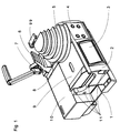
- FIG. 1 represents an overall view of a machine according to the invention, equipped only with the means necessary for bending.
- Figure 2 shows the upside down “L” frame shown in perspective with the protective cover of the work area by stamping on top, and on the front, opposite their mounting position, the parts used to fix the electronic card carrying the display and the control keys.
- FIG. 3 represents a view from above of the chassis of the machine with installation of the basic electronic circuit board and the elements of the mechanical power transmission system.
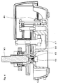
- FIG. 4 represents the machine according to the invention, seen in section along a line passing through the centers of the vertical axes of rotation of the transmission system and remaining perpendicular to the front face thanks to the recesses which it presents at each of the three intermediate axes.
- FIG. 5 represents an exploded view of the clamping module fixing on the left side of the machine to immobilize the tube at the end of which must be formed a socket or a collar, conical at 45 ° or flat at 90 °.
- FIG. 6 shows the tool-holder turret with its translational drive slide below and above the flywheel for selecting tools for shaping sockets or collars shown opposite the threaded orifices in which they are screwed.
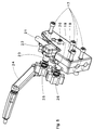
- FIG. 7 shows the module for shaping sockets by radial expansion.
- FIG. 8 represents a sectional view of one of the four latches which being integral with the front of the frame make it possible to fix there by rapid snap-fastening the improved vice which is provided with an adequate base.
- FIG. 9 shows the arrangement adopted for the control keys and the presentation of the display of the various information necessary for the user of the machine according to the invention.
- Figure 10 shows the improved vise according to the invention, seen in section along its median plane.
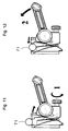
- Figure 11 shows a side view of the improved vice with a clamping tube simply placed on the edges of its two jaws.
- Figure 12 shows the result of the unscrewing action shown in Figure 11: the jaws have moved apart until the tube comes into contact with the bottom of the fixed jaw.
- This version therefore comprises a parallelepiped frame 1, a frame 2 in the shape of an "L" upside down, an electric motor installed inside the casing 10, a form of bending 5, a counterform 6, the means 7 of approach to the counterform and the gear transmission system housed in the frame in the form and the slide 8 on which the counterform moves.
- the single-phase asynchronous motor is fixed directly to the side of the frame, halfway up and perpendicular to the transmission system which it drives using a bevel gear mounted at the end of the shaft.
- the control panel 3 On the front of the machine there is the control panel 3 allowing to memorize a dozen different bending angles and to enter the instructions necessary for the factory programming of the different functions and in particular those defining the three tool strokes required for the execution of a 90 ° flat collar.
- To the right of this panel there is a flat surface having four ball locks 4 arranged along the vertices of a square to allow the rapid installation of the improved vice.
- Each lock 4 consists, as can be seen in FIG. 8, of a socket with a threaded base 16, the flange 14 of which is provided with a ball 13 which a spring 15 pushes against the crimping limiting its protrusion outside the surface of the plate 12 of the collar.
- the form of bending used on this machine has a hook 99 articulated on the top of a ramp having as many grooves as are found on the form at the base of which it is also articulated.
- this module comprises a support 18, four high-strength screws 17 passing through it to fix it in the four tapped holes 11 visible in FIG. 1, semi-dies 26, 25 of circular shape, one of which 25 is mounted on an axis 23 carried by a shoe 22 sliding on a cylindrical slide 21.
- the bringing together of the two half-dies is controlled by the arm 24 acting on a link articulated on the shoe at the level of an axis carrying a cam.
- the tube clamping force can be adjusted by varying the useful length of the link by changing the angular position of the cam.
- FIGS 2, 3 and 6 to which reference is now made respectively show the upper part of the frame, all the elements directly located on the chassis and the tool-holder turret with the adjacent parts.
- FIG. 2 we see the rib 28 on which the slide 8 is fixed.
- the release of the cover 9 makes it possible to see the four guide pins 30 of the slide 32 shown at the bottom of FIG. 6.
- its upper flat surface 34 and the bottom 31 of the upper part of the frame form a single plane which, with the cover 9 made of transparent material, defines the thickness of the volume in which the turret 36 carrying the tools 37 moves during operations for shaping sockets or collars.
- the flywheel 38 for manual selection of the shaping tools is fixed to the turret by a pin 35 which passes through an oblong opening 29 in the cover 9.
- the first is used to drive the module for shaping sockets by expanding a tool composed of sectors arranged in a crown in a ring which is screwed in place of the conical cover 42. It consists of a cam 47 visible in the figure 4, which prints an alternative movement to the axis 48 on which a spring 49 is mounted, constantly recalling it against this cam.
- the cover serves to protect the metal cone 50 when there is no tool mounted on the threaded base 51 visible in FIG. 7. The tube being threaded on the tool before its expansion, this mode of work does not requires no clamping means.
- the second used to drive the collar shaping device is constituted by the eccentric crank rod system 41 having for axis of rotation the vertical axis of the drive square 43 and whose rod 40 is articulated on the pin 33 of the slide on which is mounted the tool holder turret 36.
- the base card 39 of the control electronics is fixed to the chassis parallel to the axis of the motor.
- the control electronics must receive signals enabling it to constantly know the position of the tool-holder turret and the angular displacements of the bending shape. To do this it is associated with a potentiometer 45 shown in Figure 4 fixed on the frame and whose control rod 46 mounted coaxially on the axis of rotation of the form is driven by friction by means of a rubber piece 98 mounted in the central bore of the lower hub of the wheel carrying the drive square 9.
- FIG. 9 shows the front electronic card on which the displays are located and a waterproof mini keyboard reduced to six keys, namely "market", “stop”; “+”, “-”, to modify the value of the bending angle or that of the length of the socket or that of the diameters of the tubes if the collar function is selected; “mode” to switch from one function to another and activate the "enter” key to program different angles during successive bends.
- the programmed bending light indicator 52 flashes if one or more hangers remain to be made. When one of the indicators for the socket on annealed tube, socket on hardened tube, collar and simple bending 53 to 56 lights up, this indicates that the corresponding function has been selected.
- the section of the improved vice made along its median plane shows, according to FIG. 10, that it consists of a body 61 and a movable jaw 66 mounted pivoting on the same axis of rotation 59 secured to a base 57 having at its upper part a recess 69 constituting a fixed jaw against which the tube to be clamped is pressed by said movable jaw that the body bears on the base at a preset distance, arch-bottle with a progressive force during the raising the handle of the arm 64.
- crank pin 65 of diameter smaller than that of the bore 63 of the body transmits the necessary force to it by being mounted eccentrically inside this bore of so as to remain in contact with the wall of the latter when the arm 64 of which it is integral rotates around the axis of said bore to a position providing the desired tightening.
- a socket 67 covering a spring 68 located on the side of the fixed jaw permanently pushes the body and the movable jaw which thus remains open in an adjustable position using the knurled knob 62 of the pivot screw 58 journalling on the base of the opposite side to the fixed jaw 70. It is thus possible to quickly open the vice until the tube 71 can just pass between the two jaws to be brought into contact with the bottom of the fixed jaw. This approach opening makes it possible to pass from one tube diameter to another very quickly and without any particular precaution as soon as one observes the movements 1 and 2 recalled in FIGS. 11 and 12.
- the base 57 On its face turned away from the movable jaw, the base 57 has a flat surface 75 in which a cavity provided with mortises 72 parallel to the surface 75 opens, as well as grooves 73 and conical recesses 74. These mortises, grooves and recesses are arranged so as to cooperate with the four ball locks 4 described above, in order to maintain the vice on the machine.
- the support comprising the four square fixing means may consist of a screwed plate or, otherwise fixed to a workbench, or a fixed element. any, or even on a clamp which will itself be fixed on any element of frame or masonry.
- the support can also be designed to be held using a conventional type vice.
- the implementation of the machine according to the invention does not present any particular difficulty. As soon as it is connected to the electrical energy supply network, the display shows 90 °. This means that the machine is ready to perform the most common bending. The other functions being selected by successive presses of the mode key, it will reduce the time necessary for the execution of multiple operations as often have to do the members of many trades employing copper tubes, or tubes of decoration in their manufacture.
Landscapes
- Engineering & Computer Science (AREA)
- Mechanical Engineering (AREA)
- Bending Of Plates, Rods, And Pipes (AREA)
Applications Claiming Priority (2)
| Application Number | Priority Date | Filing Date | Title |
|---|---|---|---|
| FR9313528A FR2712215B1 (fr) | 1993-11-08 | 1993-11-08 | Machine multi-fonctions dotée d'un étau perfectionné et d'une commande électronique contrôlant le cintrage et le façonnage des extrémités de tubes. |
| FR9313528 | 1993-11-08 |
Publications (2)
| Publication Number | Publication Date |
|---|---|
| EP0656245A2 true EP0656245A2 (de) | 1995-06-07 |
| EP0656245A3 EP0656245A3 (de) | 1995-09-06 |
Family
ID=9452805
Family Applications (1)
| Application Number | Title | Priority Date | Filing Date |
|---|---|---|---|
| EP94402511A Withdrawn EP0656245A3 (de) | 1993-11-08 | 1994-11-07 | Spannstock und mit einem solchen Spannstock versehene Rohrbiegevorrichtung. |
Country Status (2)
| Country | Link |
|---|---|
| EP (1) | EP0656245A3 (de) |
| FR (1) | FR2712215B1 (de) |
Cited By (3)
| Publication number | Priority date | Publication date | Assignee | Title |
|---|---|---|---|---|
| FR2749790A1 (fr) * | 1996-06-13 | 1997-12-19 | Virax Sa | Dispositif d'etau |
| US6095508A (en) * | 1996-06-13 | 2000-08-01 | Virax S.A. | Vice device |
| WO2025215075A1 (fr) * | 2024-04-10 | 2025-10-16 | Numalliance | Dispositif de façonnage d'une extrémité d'un objet |
Families Citing this family (2)
| Publication number | Priority date | Publication date | Assignee | Title |
|---|---|---|---|---|
| IT201800010409A1 (it) * | 2018-11-16 | 2020-05-16 | Cml Int S P A | Macchina per curvare un pezzo allungato senza formazione di grinze |
| CN116727507B (zh) * | 2023-08-14 | 2023-10-20 | 诸城恒业机械有限公司 | 一种机械配件加工用弯管机 |
Family Cites Families (11)
| Publication number | Priority date | Publication date | Assignee | Title |
|---|---|---|---|---|
| DE374958C (de) * | 1922-05-02 | 1923-05-05 | Hans Bader | Einspannvorrichtung mit Exzenter |
| FR734707A (fr) * | 1931-04-25 | 1932-10-27 | Perfectionnements apportés aux étaux à commande à main | |
| CH238881A (de) * | 1943-01-18 | 1945-08-31 | Wenk Wilhelm | Vorrichtung zum Einspannen von Werkstücken. |
| US2948326A (en) * | 1957-05-31 | 1960-08-09 | Ridge Tool Co | Flaring tool |
| CH482474A (de) * | 1967-10-25 | 1969-12-15 | Frisch Geb Kg Eisenwerk | Vorrichtung zum Verformen von Rohrenden |
| US4089160A (en) * | 1977-02-18 | 1978-05-16 | Beaston Bud A | Horseshoe bending apparatus and vise |
| FR2483271A1 (fr) * | 1980-05-28 | 1981-12-04 | Gateau Internal | Appareil de faconnage de tubes |
| DE3326559C2 (de) * | 1983-07-22 | 1985-06-27 | Emag Maschinenfabrik Gmbh, 7335 Salach | Verfahren und Vorrichtung zum Endbearbeiten von Oberflächen von Rohren |
| US4719577A (en) * | 1985-05-29 | 1988-01-12 | Eley David L | Bending machine with digital electronic control of bend angle |
| US4732025A (en) * | 1987-05-22 | 1988-03-22 | Ap Industries, Inc. | Precision bending apparatus and process |
| US4729552A (en) * | 1987-08-03 | 1988-03-08 | George Pempek | Vertical vise |
-
1993
- 1993-11-08 FR FR9313528A patent/FR2712215B1/fr not_active Expired - Fee Related
-
1994
- 1994-11-07 EP EP94402511A patent/EP0656245A3/de not_active Withdrawn
Cited By (4)
| Publication number | Priority date | Publication date | Assignee | Title |
|---|---|---|---|---|
| FR2749790A1 (fr) * | 1996-06-13 | 1997-12-19 | Virax Sa | Dispositif d'etau |
| US6095508A (en) * | 1996-06-13 | 2000-08-01 | Virax S.A. | Vice device |
| WO2025215075A1 (fr) * | 2024-04-10 | 2025-10-16 | Numalliance | Dispositif de façonnage d'une extrémité d'un objet |
| FR3161134A1 (fr) * | 2024-04-10 | 2025-10-17 | Numalliance | Dispositif de façonnage d’une extrémité d’un objet |
Also Published As
| Publication number | Publication date |
|---|---|
| FR2712215A1 (fr) | 1995-05-19 |
| FR2712215B1 (fr) | 1996-12-20 |
| EP0656245A3 (de) | 1995-09-06 |
Similar Documents
| Publication | Publication Date | Title |
|---|---|---|
| JPH03173603A (ja) | ビスケット接合カッター | |
| WO2002066208A1 (fr) | Porte-brucelles | |
| EP0020272A1 (de) | Beweglicher Gerätehalter für die Arbeit an einer Rohrplatte | |
| FR3043925A1 (fr) | Formage d'un coude dans une ondulation | |
| EP0656245A2 (de) | Spannstock und mit einem solchen Spannstock versehene Rohrbiegevorrichtung | |
| WO2005102589A1 (fr) | Dispositif de decoupe au laser pour detourer, ajouter, poinconner ou similaire comprenant un support pour la tete laser amovible du bati d’une machine-outil | |
| FR3033654A1 (fr) | Porte mouvement d'une piece d'horlogerie | |
| JPH1034566A (ja) | 照明付き電動工具 | |
| FR2737562A1 (fr) | Appareil fixe de support reconfigurable, particulierement destine aux machines de mesure, et procede de configuration s'y rapportant | |
| US5203062A (en) | Insertion apparatus for pressing a ring into a pipe | |
| EP1375072A2 (de) | Drehmoment-Werkzeug, insbesondere Schlüssel, mit Schnappmitteln zum Einstellen des Drehmoments | |
| EP1476287B1 (de) | Töpferscheibe mit einer führungseinrichtung zur formung | |
| CH697003A5 (fr) | Machine de perçage à main et à outils multiples. | |
| CH631889A5 (fr) | Dispositif porte-outil pour travaux dentaires. | |
| WO1982001334A1 (fr) | Tour automatique a commande numerique | |
| FR2657035A1 (fr) | Machine pour l'affutage de forets helicouidaux. | |
| FR2660229A1 (fr) | Outil a usages multiples. | |
| FR2555927A1 (fr) | Magasin d'outils pour machine-outil automatique a broche rotative porte-outil montee dans une tete d'usinage | |
| CH673607A5 (en) | Multipurpose machine tool - with flexibility enhanced by using large number of its working axes | |
| EP0761358B1 (de) | Gewindebohrwerkzeug verwendet in einer Presse | |
| CH615854A5 (en) | Transfer machine | |
| WO2005000128A1 (fr) | Dispositif de positionnement de guide de coupe osseuse | |
| BE1010498A6 (fr) | Dispositif pour le positionnement de pieces par rapport a un mandrin. | |
| FR2709693A1 (fr) | Etau pour clés à gorges frontales pour serrure à pompe ainsi que machine à reproduire des clés munie de deux étaux de ce type. | |
| FR2665657A1 (fr) | Decolleteuse electrique portable. |
Legal Events
| Date | Code | Title | Description |
|---|---|---|---|
| PUAI | Public reference made under article 153(3) epc to a published international application that has entered the european phase |
Free format text: ORIGINAL CODE: 0009012 |
|
| AK | Designated contracting states |
Kind code of ref document: A2 Designated state(s): BE DE ES FR GB GR IT NL PT |
|
| PUAL | Search report despatched |
Free format text: ORIGINAL CODE: 0009013 |
|
| AK | Designated contracting states |
Kind code of ref document: A3 Designated state(s): BE DE ES FR GB GR IT NL PT |
|
| 17P | Request for examination filed |
Effective date: 19960212 |
|
| 17Q | First examination report despatched |
Effective date: 19970113 |
|
| STAA | Information on the status of an ep patent application or granted ep patent |
Free format text: STATUS: THE APPLICATION HAS BEEN WITHDRAWN |
|
| 18W | Application withdrawn |
Withdrawal date: 19970712 |