EP0656293A1 - Système de tourelle d'amarrage pour bateau - Google Patents
Système de tourelle d'amarrage pour bateau Download PDFInfo
- Publication number
- EP0656293A1 EP0656293A1 EP94304113A EP94304113A EP0656293A1 EP 0656293 A1 EP0656293 A1 EP 0656293A1 EP 94304113 A EP94304113 A EP 94304113A EP 94304113 A EP94304113 A EP 94304113A EP 0656293 A1 EP0656293 A1 EP 0656293A1
- Authority
- EP
- European Patent Office
- Prior art keywords
- turret
- vessel
- mooring
- bearing
- arm
- Prior art date
- Legal status (The legal status is an assumption and is not a legal conclusion. Google has not performed a legal analysis and makes no representation as to the accuracy of the status listed.)
- Granted
Links
- 239000000463 material Substances 0.000 claims description 4
- 238000000034 method Methods 0.000 claims description 4
- 238000005096 rolling process Methods 0.000 claims description 4
- 230000008878 coupling Effects 0.000 claims description 2
- 238000010168 coupling process Methods 0.000 claims description 2
- 238000005859 coupling reaction Methods 0.000 claims description 2
- 239000012530 fluid Substances 0.000 description 6
- 238000012423 maintenance Methods 0.000 description 4
- 230000008439 repair process Effects 0.000 description 4
- 230000008901 benefit Effects 0.000 description 2
- 238000010276 construction Methods 0.000 description 2
- 230000007246 mechanism Effects 0.000 description 2
- 238000005452 bending Methods 0.000 description 1
- 230000000694 effects Effects 0.000 description 1
- 238000009434 installation Methods 0.000 description 1
- 238000004519 manufacturing process Methods 0.000 description 1
- 238000012986 modification Methods 0.000 description 1
- 230000004048 modification Effects 0.000 description 1
- 125000006850 spacer group Chemical group 0.000 description 1
Images


Classifications
-
- B—PERFORMING OPERATIONS; TRANSPORTING
- B63—SHIPS OR OTHER WATERBORNE VESSELS; RELATED EQUIPMENT
- B63B—SHIPS OR OTHER WATERBORNE VESSELS; EQUIPMENT FOR SHIPPING
- B63B21/00—Tying-up; Shifting, towing, or pushing equipment; Anchoring
- B63B21/50—Anchoring arrangements or methods for special vessels, e.g. for floating drilling platforms or dredgers
- B63B21/507—Anchoring arrangements or methods for special vessels, e.g. for floating drilling platforms or dredgers with mooring turrets
Definitions
- One type of vessel has a turret rotatably mounted on the vessel hull, so the turret does not rotate with the hull.
- a mooring structure such as several catenary lines extending up from the sea floor, connect to the turret, so mooring forces that limit vessel drift are transmitted through the turret to the vessel.
- a conduit with several hoses may extend from the sea floor up to the nonrotating turret, and through a fluid swivel structure at the top of the turret to pipes on the vessel.
- a typical prior art turret is supported on the vessel by upper and lower bearings to withstand both the constant vertical load on the turret due to the weight of the mooring lines, and to withstand large net horizontal mooring forces applied during storms.
- One problem arising with such a system is that the upper and lower bearings have to be mounted and maintained precisely concentric on the vessel hull, which is very difficult to achieve. Even when concentricity is achieved, it can be lost by deformations of the ship hull. Still another problem is that the lower bearing is difficult to maintain and repair in the field. While the upper bearing lies above the sea surface, the lower bearing lies a considerable distance such as twenty meters below the sea surface, where it is difficult to replace large parts.
- the present invention provides a mooring system for a vessel that has a hull with walls forming a primarily vertically-extending turret cavity, a turret lying at least adjacent to said cavity and having an upper portion, a turret bearing that couples said turret to said hull to rotatably support said turret in rotation about a turret axis on said hull, and a mooring structure for mooring said vessel, wherein said mooring structure has a lower portion coupled to the seafloor and an upper portion, characterised by a connecting apparatus coupled to the upper portion of said mooring structure to receive mooring loads transmitted through said mooring structure, a vessel lower bearing device mounted on said vessel about said axis and lying below said turret upper portion, said connecting apparatus bearing against said vessel lower bearing device to transmit a majority of horizontal components of mooring loads from said mooring structure to said vessel bearing device, said connecting apparatus being shiftable horizontally substantially independently of said turret.
- a turret vessel mooring system which avoids the need for accurate alignment of upper and lower turret bearings, which facilitates repair of the underwater lower bearing, and which minimizes internal loading of the turret.
- the system includes a vessel lower bearing device lying at the lower portion of the turret cavity and mounted on the vessel hull independently of the turret.
- a connecting apparatus that is coupled to the upper portions of mooring lines or other mooring structure, transmits the horizontal components of the mooring loads directly to the independently-mounted vessel lower bearing device. Thus, large horizontal mooring load components are not applied to the turret.
- One connecting apparatus comprises a group of arms spaced about the lower end of the turret, with each arm having an upper end pivotally mounted on the turret and a lower end connected to the upper end of a mooring line.
- Each arm carries a bearing pad that presses horizontally against the vessel lower bearing device to transmit substantially all horizontal forces directly to the vessel hull through the lower bearing device.
- the vertical components of mooring loads applied to the arms are transmitted through the pivotally mounted upper arm ends to the turret.
- the turret bearing connected to the upper end of the turret supports substantially all of the vertical mooring load components.
- the present invention provides a vessel that floats at the surface of a sea
- the vessel has a hull comprising cavity walls forming a vertically-extending cavity with upper and lower portions, has a turret lying at least adjacent to said turret cavity, and has a turret bearing lying above the level of said sea surface and supporting said turret upper portion in rotation about a vertical axis with respect to said vessel hull
- the system includes a mooring structure that is anchored to the seafloor and which applies mooring forces to said vessel including horizontal force components to limit vessel drift from a quiescent vessel position and a vertical weight force component representing the net weight of said mooring structure that is supported by said vessel
- said vessel has a vessel lower bearing device mounted on said vessel hull around said axis independently of said turret and lying at a height below the sea surface, and including connecting apparatus which is connected to said mooring structure and which is coupled to both said vessel lower bearing device and said turret and which applies
- the present invention provides a method for mooring a vessel that floats at the surface of a sea, where the vessel has a hull with cavity walls forming a vertically-extending cavity with upper and lower portions, has a turret lying at least adjacent to said turret cavity, and has a turret bearing lying above the level of said sea surface and supporting said turret upper portion in rotation about a vertical turret axis with respect to said vessel hull, wherein the system includes a mooring structure that is anchored to the seafloor and which applies mooring forces to said vessel including horizontal and vertical force components, characterised by applying said horizontal force components from said mooring structure primarily to said hull independently of said turret, and applying said vertical force components from said mooring structure primarily to said turret so said vertical force components are supported by said hull through said turret bearing.
- Fig. 1 illustrates a mooring system 10 which includes a vessel 12 that forms a primarily vertically extending turret cavity 14.
- a turret 16 lies at least adjacent to the cavity as by lying in it, and the turret is rotatable about a substantially vertical turret axis 20 with respect to the vessel hull 22.
- a mooring structure 24 such as a group of catenary lines (which may be in the form of chains and/or cables) moors the vessel. The lines extend downwardly and in different horizontal directions from the vessel.
- the turret cavity 14 lies within the main part 25 of the vessel hull.
- the hull includes a structure 26 extending beyond the bow of the original vessel, to provide a cavity 28 which supports a turret 30 lying beyond the main part of the hull.
- the present invention is applicable to both types of systems.
- Fig. 2 shows the system in a quiescent configuration or position, when there is no substantial wind, waves, or currents, so the turret axis 20 is vertical and the mooring lines 32, 34 apply equal mooring loads.
- the particular system is used to produce oil from an undersea well 40 which is connected by a flexible pipe or conduit 42 to the turret, so fluids can flow through a multiple conduit fluid swivel 44 to pipes 46 on the vessel.
- the conduit 42 may contain several hoses, or several conduits can be used.
- the weight of the turret is supported by a turret bearing 60.
- the turret bearing is coupled to an upper portion 62 of the turret which lies at an upper portion 64 of the turret cavity, and with both lying above the sea surface S.
- Lower portions 66, 68 respectively of the turret and cavity lie below the sea surface.
- the upper ends of the mooring lines such as 32, 34 are coupled through a connecting apparatus 70 to the vessel.
- the connecting apparatus includes a group of fairleads 72 and brackets 74.
- Each mooring line such as 32 is slidably guided through a corresponding fairlead 72 which serves as a connection portion, with the upper end 76 of the mooring line attached to a corresponding bracket 74 which is fixed to the upper portion 62 of the turret.
- the fairleads 72 and brackets 74 are arranged so the upper portion 80 of the mooring line extends primarily vertically between them.
- the mooring line upper portion 80 can apply primarily only a vertical force component to the turret.
- preferably more than 83% of the horizontal load components are transmitted to the vessel lower bearing device.
- Fig. 5 shows some details of the fairlead or line guide 72.
- the mooring line 32 is guided in slidable movement through a guide passage 84.
- the horizontal component of tension in the mooring line presses a bearing pad 86 of the line guide 72 firmly against the vessel lower bearing device 82.
- the mooring line slides only short distances on the guide, so it is possible to provide a pivot connection of the mooring line to the line guide to provide a substantial slidable connection that minimizes wear.
- the line guide bearing pad 86 bears against the vessel lower bearing device for moderately low frictional sliding contact thereagainst.
- the line guide 72 has secondary bearings 90, 92 that bear against corresponding secondary bearing devices 94, 96 on the vessel hull, to prevent loss of the line guide.
- almost all of the force applied by the mooring line 32 to the line guide 72 is the horizontal component H of the mooring line tension or load L, and is applied to the bearing device 82.
- Fig. 4 shows spacers 98 which keep eight line guides 72 uniformly spaced apart, so they all turn in unison around the vessel lower bearing device 82.
- the vessel lower bearing device 82 does not have to be mounted and maintained precisely concentric with the turret bearing 60. Because of manufacturing tolerances and warping that occurs during construction and over the life of a vessel, it previously has been difficult to mount and maintain upper and lower turret bearings precisely concentric. Although applicant prefers to locate the vessel lower bearing device 82 substantially concentric with the upper turret bearing 60 and therefore with the turret axis 20, such locating need not be accomplished with precision.
- the bearing device is shiftable horizontally independently of the turret, and a small amount of shifting (e.g. a few centimeters where the turret has a diameter of 10 meters) does not have much effect. It can be seen that the fairleads or connection portions 72, can shift horizontally substantially independently of the lower portion 66 of the turret.
- Another advantage of the present system is that only small portions of the horizontal load components are applied to the turret 16. Also, these small horizontal portions are applied to the upper portion 62 of the turret, rather than to the lower turret portion where any horizontal force could result in a large moment arm with respect to the upper turret bearing 60. As a result, there is little horizontal loading of the turret bearing even in a severe storm when there is a large net horizontal loading that must be withstood by the vessel. It is noted that the vertical force components applied to the turret represent primarily the weight of the lines and are relatively constant between good weather conditions and severe weather.
- the turret bearing 60 includes rolling elements such as roller bearings 100 or bogies that rotate on raceways, with one raceway 102 mounted on the hull and the other 104 mounted on the turret. Accordingly, there is relatively little wear despite constant loading. Large horizontal load components H are encountered only in severe weather, which occurs only occasionally. As a result, there is relatively small wear at the vessel lower bearing device 82 and at the bearing pads 86 on the line guides. This is desirable because this sliding bearing arrangement 82, 86 undergoes considerable wear when high loads are applied, even though they are of low sliding friction bearing material. The bearing pads 86 are of relatively small weight, and can be replaced in the field.
- the effective coefficient of friction for rolling members such as at the upper turret bearing 60 is relatively low, such as less than 1%, so the turret will readily turn even under light loading.
- the coefficient of friction at the vessel lower bearing device 82 and bearing pads 86 is higher, such as perhaps 10%.
- the horizontal load component H is usually small and does not significantly retard rotation of the turret which is usually primarily under the influence of the large vertical load component V. In severe weather, the horizontal load component H is large, and any rotational misalignment of the turret with the mooring lines results in a large turret turning force.
- Fig. 6 is a partial sectional view of a mooring system 110 constructed in accordance with another embodiment of the invention.
- the only vertical load on the turret 112 is due to the weight of the turret and the weight of the conduit 114 and equipment attached to the conduit.
- the weight of the turret and the weight it carries is supported by an upper turret bearing 116.
- the upper ends of mooring lines such as 120, 122 are fixed to fairleads 124 which are rotatably supported on the vessel hull 130 independently of the turret.
- the vessel carries a horizontal vessel bearing device 132 in the form of a ring-shaped slider bearing to take the horizontal load component H.
- the vessel also carries half of a vertical bearing 134 which can include rolling elements, to take the vertical load component V. Due to the fact that the mooring lines such as 120 are not connected to the turret 112, a separate turret rotating mechanism 140 is provided to turn the turret with respect to the vessel hull, so the turret remains substantially unturned as the vessel turns, to avoid twisting of the conduit 114.
- the mechanism can include a sensor 142 that senses turning of the vessel and which operates a motor 144 that turns gears 146, 148 to turn the turret.
- a rod 149 can be provided that extends from a fairlead to a slot in the turret, to cause the turret to turn with the fairlead's while allowing them to independently tilt and shift slightly.
- the mooring system 110 of Fig. 6 avoids the need for mounting two bearings precisely concentric and avoids appreciable tilt of the turret, it has the disadvantage that the vertical bearing 134 lies underwater, where maintenance and repair is very difficult, especially for a ball or roller bearing which has large and heavy raceways. As a result, the system 110 of Fig. 6 is not preferred.
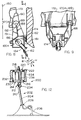
- Figs. 7 - 9 illustrate a preferred mooring system 150 wherein the mooring structure 152 comprises mooring lines such as 162, 164, and the connecting apparatus 154 comprises arms 166 connected to the mooring lines, with each arm pivotally mounted about a corresponding arm axis 170 on the turret 172.
- the particular system shown has four arms (for four mooring lines), with three of them shown at 166A, 166B, and 166C.
- Each arm has an upper portion that is pivotally mounted on the turret about a corresponding substantially horizontal arm axis 170 such as 170A, 170B, and 170C.
- Each arm axis extends substantially in a circumferential direction, that is, perpendicular to a line (e.g. R in Fig. 10) that extends radially from the turret axis 180.
- Each arm has bearing pads 174 that press radially outwardly (with respect to turret axis 180) against an annular inner surface 181 of a vessel lower bearing device 182 which is in the form of a bearing ring.
- the turret is rotatably mounted to the vessel hull 183 (Fig. 7) by a turret bearing 185 that lies above the sea surface S.
- mooring line 162 is attached to a mount 184 which is pivotally mounted about a horizontal mount axis 186 on the arm 166A.
- the mooring line can be directly fixed to the arm.
- One or more mooring lines can be coupled to each arm.
- the mooring lines generally extend at an angle B to the vertical of about 35° in the quiescent position of the vessel, with the angle increasing as forces (wind, waves, and currents) are applied to the vessel. Even the relatively small horizontal component of the mooring load in the quiescent position of the vessel results in the arm 166A lying in a position where its bearing pad 174 constantly engages the lower bearing device 182.
- the arm transmits sideward forces that rotate the turret relative to the vessel hull.
- the bearing pads 174 are mounted on lower portions 191 of the arms that serve as connecting portions, and the mooring line attachment locations at 186 preferably lie no higher than the pads 174.
- the main wearing part is likely to be the bearing pads 174, and these are relatively small items that can be readily replaced.
- the surface 181 of the vessel lower bearing ring is of a hard material that wears very slowly against the softer material of the bearing pads.
- the vessel has a dead weight (when full with oil) of 200,000 metric tons, lies in a sea of 500 feet (150 meters) depth, and when loaded the bottom of the hull lies twenty meters below the sea surface and the deck lies five meters above the sea surface.
- the vertical load comprises a turret weight of 1000 metric tons (2,200,000 pounds), chain mooring lines of a weight of about 1000 metric tons (which varies as the vessel drifts and chain is picked up or laid down from the sea surface), and a fluid carrying conduit which applies a weight of 100 metric tons.
- the system is designed for a maximum horizontal load of about 1,000 metric tons for the most severe weather to be encountered.
- the horizontal load on each of four mooring lines is about ten metric tons, which is applied in different horizontal directions to the arms.
- the turret bearing such as 185 in Fig. 7, will always carry at least the weight of the fluid conduit, i.e. will always carry at least 5% of the total weight on the vessel hull (100 tons is 5% of 1000 tons plus 1000 tons), and at least 10% of the vertical mooring load (100 is 10% of 1000 tons), and preferably carries at least 50% of the weight and of the vertical mooring load.
- Fig. 11 is a view of the mooring system of Fig. 7, showing a winch device 241 which is used during maintenance of one of the arm 166C, as to replace its bearing pads 174.
- a cable device (chain, cable, etc.) 243 extends from the winch device around a sheave 245 to a pad eye 247 on the arm.
- the winch device is operated to tension the cable device and thereby pivot the arm so its bearing pads are readily accessible to divers for replacement.
- the winch device 241 and sheave 245 are mounted on the turret, so any turning, or other motion of the turret does not affect the arm pivoting apparatus. Replacement is done when the seas are quiescent. Any device that can be operated by a person, can be used to pivot the arm so its bearing pad is moved away from the vessel lower bearing device.
- Fig. 10 is a view taken on line 10-10 of Fig. 7, but with the turret 172 shown in phantom lines. Also, Fig. 10 shows cables 194, 196 that connect opposite arms, such as 166B and 166D. The cables, which lie below the turret, are tensioned or tightened enough to transmit much of the horizontal load component from one arm to the opposite one. This reduces the force with which the pads 174 press against the vessel bearing device ring 182, especially when the vessel is in its quiescent position, to reduce bearing and pad wear. It is possible to use the winches 241 (Fig. 11) that pivot the arms for pad replacement, to similarly reduce pad wear.
- Fig. 12 illustrates another system 200, wherein the mooring structure 202 is in the form of a riser 204 whose lower end is anchored by a chain table 206 and catenary anchor lines 208.
- the upper end 210 of the riser is coupled through a universal joint 212 (which allows pivoting about two primarily horizontal axes) that hangs from a connecting apparatus 214.
- the connecting apparatus 214 includes a lower connecting part 216 which is hung by a group of rods 218 from the turret 220.
- the turret is supported by a turret bearing 222 on the vessel hull 224.
- the connecting part 216 carries bearing pads 230 that can press against a vessel bearing device 232 which is in the form of a lower bearing ring.
- a conduit 234 extends through the lower connecting part and includes a substantially rigid pipe 236 that extends to the turret 220.
- the rods 218 and pipe 236 are thin and long enough that they can bend slightly to permit the lower connecting part 216 to shift horizontally slightly (e.g. a few centimeters for a 10 meter diameter turret), and therefore act like a universal joint that allows only limited pivoting (i.e. up to 3° of pivoting).
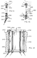
- Figs. 13 and 14 illustrate another system 240 which includes arms 242 with upper ends 244 pivotally mounted about axes 246 on a turret 250.
- the turret is rotatably mounted about its axis 252 by a bearing 254 on the vessel hull 256, to lie at least adjacent to the cavity.
- Each arm has a lower end 258 with a chain coupling 260 coupled to a mooring line 262, and with a bearing pad 264.
- Each bearing pad bears against a vessel lower bearing ring 266 that is directly mounted on the vessel hull.
- the arms 242 are shown as including vertically elongated I-beams which are rigid against bending.
- Fig. 15 illustrates one arm 280 of a system 282 similar to that of Figs. 13 and 14, except that the top of the arm is fixed to a mount 284 that is fixed to the turret 286.
- the arm includes bendable beams 291 - 293. The beams allow the arm lower end 296 to deflect horizontally a small distance in a radially outward direction 298 to press against the vessel lower bearing ring 300. However, the beams resist more than small deflection of the arm lower end in a circumferential direction 302, relative to the turret, to assure turret turning.
- the invention provides a mooring and fluid transfer system for a vessel which includes a turret that rotates about a substantially vertical axis, which avoids the application of large torque to the turret that tends to tilt it, which avoids the need for mounting upper and lower turret bearings precisely concentric on the vessel hull, and which facilitates maintenance of the lower underwater bearing.
- a mooring structure is coupled to a connecting apparatus that bears against a vessel lower bearing device to transmit horizontal forces therethrough to the hull, where the vessel lower bearing device is mounted on the hull independently of the turret.
- the vessel lower bearing device is mounted independently of the turret, in that the bearing device passes horizontal loads to the hull substantially without such loads passing through the turret, and in that the bearing device does not rotatably support the turret and need not contact it.
- the turret bearing carries at least 10% of the vertical component of the mooring load, and preferably at least half of it. Less than half of the horizontal component of the mooring load is transmitted to the turret.
- the connecting apparatus includes a group of arms pivotally mounted on the lower portion of the turret to transmit vertical loads through the pivot mount, the arms having bearing pads that bear against a ring-shaped vessel lower bearing device mounted on the vessel hull.
Landscapes
- Chemical & Material Sciences (AREA)
- Engineering & Computer Science (AREA)
- Combustion & Propulsion (AREA)
- Mechanical Engineering (AREA)
- Ocean & Marine Engineering (AREA)
- Magnetic Bearings And Hydrostatic Bearings (AREA)
- Jib Cranes (AREA)
- Specific Conveyance Elements (AREA)
- Discharge Heating (AREA)
- Catching Or Destruction (AREA)
Applications Claiming Priority (2)
| Application Number | Priority Date | Filing Date | Title |
|---|---|---|---|
| US162338 | 1993-12-02 | ||
| US08/162,338 US5381750A (en) | 1993-12-02 | 1993-12-02 | Vessel turret mooring system |
Publications (2)
| Publication Number | Publication Date |
|---|---|
| EP0656293A1 true EP0656293A1 (fr) | 1995-06-07 |
| EP0656293B1 EP0656293B1 (fr) | 1998-09-09 |
Family
ID=22585201
Family Applications (1)
| Application Number | Title | Priority Date | Filing Date |
|---|---|---|---|
| EP94304113A Expired - Lifetime EP0656293B1 (fr) | 1993-12-02 | 1994-06-08 | Système de tourelle d'amarrage pour bateau |
Country Status (5)
| Country | Link |
|---|---|
| US (1) | US5381750A (fr) |
| EP (1) | EP0656293B1 (fr) |
| BR (1) | BR9404808A (fr) |
| CA (1) | CA2134314C (fr) |
| NO (1) | NO310340B1 (fr) |
Cited By (10)
| Publication number | Priority date | Publication date | Assignee | Title |
|---|---|---|---|---|
| WO1997029940A1 (fr) * | 1996-02-16 | 1997-08-21 | Petroleum Geo-Services A.S | Navire de production ayant une coque a ligne de flottaison sinusoidale |
| WO1998030436A1 (fr) * | 1997-01-08 | 1998-07-16 | Den Norske Stats Oljeselskap A.S | Appareil permettant d'ancrer un navire et de transferer une charge flottante |
| FR2771703A1 (fr) * | 1997-12-03 | 1999-06-04 | Framatome Sa | Dispositif d'amarrage pour une structure flottante |
| WO1999044883A1 (fr) * | 1998-03-04 | 1999-09-10 | Kværner Oil & Gas A.S | Navire de surface |
| US6869325B1 (en) | 2000-01-13 | 2005-03-22 | Statoil Asa | Rotating tower system for transferring hydrocarbons to a ship |
| WO2012163394A1 (fr) | 2011-05-30 | 2012-12-06 | Bluewater Energy Services B.V. | Ensemble d'amarrage pour navire |
| WO2013027036A1 (fr) | 2011-08-19 | 2013-02-28 | Axis Limited | Système d'amarrage et ensemble raccord |
| KR20150137607A (ko) * | 2014-05-30 | 2015-12-09 | 삼성중공업 주식회사 | 터렛 베어링 |
| US10696359B2 (en) | 2016-05-24 | 2020-06-30 | Bluewater Energy Services B.V. | Turret assembly |
| US11655010B2 (en) | 2019-12-13 | 2023-05-23 | Bluewater Energy Services B.V. | Assembly of a vessel and a turret |
Families Citing this family (22)
| Publication number | Priority date | Publication date | Assignee | Title |
|---|---|---|---|---|
| US5476059A (en) * | 1994-12-20 | 1995-12-19 | Imodco, Inc. | Turret drive mechanism |
| US6085851A (en) * | 1996-05-03 | 2000-07-11 | Transocean Offshore Inc. | Multi-activity offshore exploration and/or development drill method and apparatus |
| GB9617209D0 (en) | 1996-08-16 | 1996-09-25 | Mcdermott Sa J Ray | Vessel turret systems |
| EP0831022A1 (fr) * | 1996-09-20 | 1998-03-25 | Single Buoy Moorings Inc. | Stoppeur pour chaínes d'ancre à déclenchement rapide |
| NO974639L (no) | 1997-10-08 | 1999-04-09 | Hitec Asa | FremgangsmÕte og arrangement for fort°yning av et skip, sµrlig et skip for olje-/ og/eller gassproduksjon |
| EP0962384A1 (fr) * | 1998-06-05 | 1999-12-08 | Single Buoy Moorings Inc. | Dispositif de chargement d'un navire |
| FR2782341B1 (fr) * | 1998-08-11 | 2000-11-03 | Technip Geoproduction | Installation d'exploitation d'un gisement en mer et procede d'implantation d'une colonne montante |
| US6494271B2 (en) | 2001-04-25 | 2002-12-17 | Exxonmobil Upstream Research Company | Offshore floating production method |
| US6663320B1 (en) * | 2002-09-25 | 2003-12-16 | Single Buoy Moorings Inc. | Anchor line connector |
| US7063032B2 (en) * | 2003-04-23 | 2006-06-20 | Fmc Technologies, Inc. | Upper bearing support assembly for internal turret |
| US7802636B2 (en) | 2007-02-23 | 2010-09-28 | Atwood Oceanics, Inc. | Simultaneous tubular handling system and method |
| FR2928898B1 (fr) * | 2008-03-21 | 2010-04-16 | Saipem Sa | Support flottant comprenant un touret equipe d'une bouee d'amarrage de conduites de liaison fond/surface deconnectable |
| CN102448809A (zh) * | 2009-05-12 | 2012-05-09 | 瑞士单浮筒系泊公司 | 分步式cam系泊系统 |
| US8215888B2 (en) | 2009-10-16 | 2012-07-10 | Friede Goldman United, Ltd. | Cartridge tubular handling system |
| WO2013131903A1 (fr) * | 2012-03-05 | 2013-09-12 | Single Buoy Moorings, Inc. | Système de palier submergé pour navire amarré par tourelle |
| US8671864B2 (en) * | 2012-04-13 | 2014-03-18 | Sofec, Inc. | Turret bearing structure for vessels |
| US8950349B2 (en) | 2012-08-17 | 2015-02-10 | Sofec, Inc. | Replaceable roller bearing |
| SE536217C2 (sv) * | 2012-08-24 | 2013-07-02 | Förfarande för förankring av farkost samt anordning härför | |
| US9944357B2 (en) * | 2013-10-15 | 2018-04-17 | Single Buoy Moorings Inc. | Mooring arrangement and yoke for said mooring arrangement |
| KR101689031B1 (ko) * | 2014-09-12 | 2017-01-02 | 대우조선해양 주식회사 | 플로트 오버용 터렛 바지선 및 이에 의한 안벽 로드아웃 방법 |
| CN106275276B (zh) * | 2016-07-29 | 2018-08-03 | 中国船舶重工集团公司第七一九研究所 | 一种自动复位弹性套筒式单点系泊系统 |
| WO2018107160A1 (fr) * | 2016-12-09 | 2018-06-14 | Trendsetter Vulcan Offshore, Inc. | Systèmes d'interface de complétion à utiliser avec des blocs d'obturation de surface |
Citations (3)
| Publication number | Priority date | Publication date | Assignee | Title |
|---|---|---|---|---|
| US3774562A (en) * | 1972-06-12 | 1973-11-27 | Global Marine Inc | 360{20 {11 rotary anchoring system with differential drive capability |
| EP0259072A1 (fr) * | 1986-08-27 | 1988-03-09 | Taylor Woodrow Construction Limited | Système d'amarrage et système pour amarrer une structure flottante |
| EP0399719A1 (fr) * | 1989-05-24 | 1990-11-28 | Golar-Nor Offshore A.S. | Porteur pour plaque tournante utilisée pour ancrer des navires |
Family Cites Families (13)
| Publication number | Priority date | Publication date | Assignee | Title |
|---|---|---|---|---|
| US3279404A (en) * | 1963-12-20 | 1966-10-18 | Offshore Co | Floating mooring system |
| US3620181A (en) * | 1969-07-02 | 1971-11-16 | North American Rockwell | Permanent ship mooring system |
| US4650431A (en) * | 1979-03-28 | 1987-03-17 | Amtel, Inc | Quick disconnect storage production terminal |
| US4305341A (en) * | 1979-10-09 | 1981-12-15 | Chicago Bridge & Iron Company | Spindle moored ship |
| GB2118903B (en) * | 1982-04-16 | 1985-09-25 | Mitsui Shipbuilding Eng | Floating offshore structure |
| US4637335A (en) * | 1982-11-01 | 1987-01-20 | Amtel, Inc. | Offshore hydrocarbon production system |
| DE3344116A1 (de) * | 1983-12-07 | 1985-06-20 | Blohm + Voss Ag, 2000 Hamburg | Verankerungs- und uebernahme-system fuer fluessige und gasfoermige medien an einem schiffskoerperende eines tankers |
| US4604961A (en) * | 1984-06-11 | 1986-08-12 | Exxon Production Research Co. | Vessel mooring system |
| DE3430628C2 (de) * | 1984-08-20 | 1986-08-07 | Blohm + Voss Ag, 2000 Hamburg | Ventilstation zum Verbinden mehrerer auf dem Meeresgrund vorhandener Bohrlöcher für Öl- und/oder Erdgasförderung |
| US4701143A (en) * | 1984-10-17 | 1987-10-20 | Key Ocean Services, Inc. | Vessel mooring system and method for its installation |
| NO171628C (no) * | 1987-10-12 | 1993-04-14 | Pusnes As | Dreiehode |
| US4955310A (en) * | 1988-12-08 | 1990-09-11 | Jack Pollack | Bearing arrangement for single point terminal |
| US5178087A (en) * | 1991-01-16 | 1993-01-12 | Single Buoy Moorings, Inc. | Mooring device |
-
1993
- 1993-12-02 US US08/162,338 patent/US5381750A/en not_active Expired - Lifetime
-
1994
- 1994-06-08 EP EP94304113A patent/EP0656293B1/fr not_active Expired - Lifetime
- 1994-10-25 CA CA002134314A patent/CA2134314C/fr not_active Expired - Fee Related
- 1994-12-01 NO NO19944629A patent/NO310340B1/no unknown
- 1994-12-01 BR BR9404808A patent/BR9404808A/pt not_active IP Right Cessation
Patent Citations (3)
| Publication number | Priority date | Publication date | Assignee | Title |
|---|---|---|---|---|
| US3774562A (en) * | 1972-06-12 | 1973-11-27 | Global Marine Inc | 360{20 {11 rotary anchoring system with differential drive capability |
| EP0259072A1 (fr) * | 1986-08-27 | 1988-03-09 | Taylor Woodrow Construction Limited | Système d'amarrage et système pour amarrer une structure flottante |
| EP0399719A1 (fr) * | 1989-05-24 | 1990-11-28 | Golar-Nor Offshore A.S. | Porteur pour plaque tournante utilisée pour ancrer des navires |
Cited By (16)
| Publication number | Priority date | Publication date | Assignee | Title |
|---|---|---|---|---|
| WO1997029940A1 (fr) * | 1996-02-16 | 1997-08-21 | Petroleum Geo-Services A.S | Navire de production ayant une coque a ligne de flottaison sinusoidale |
| GB2324277A (en) * | 1996-02-16 | 1998-10-21 | Petroleum Geo Services As | Production vessel with sinusoidal waterline hull |
| GB2324277B (en) * | 1996-02-16 | 2000-11-01 | Petroleum Geo Services As | Production vessel with sinusoidal waterline hull |
| WO1998030436A1 (fr) * | 1997-01-08 | 1998-07-16 | Den Norske Stats Oljeselskap A.S | Appareil permettant d'ancrer un navire et de transferer une charge flottante |
| FR2771703A1 (fr) * | 1997-12-03 | 1999-06-04 | Framatome Sa | Dispositif d'amarrage pour une structure flottante |
| EP0921061A1 (fr) * | 1997-12-03 | 1999-06-09 | NFM Technologies | Dispositif d'amarrage pour une structure flottante |
| WO1999044883A1 (fr) * | 1998-03-04 | 1999-09-10 | Kværner Oil & Gas A.S | Navire de surface |
| US6869325B1 (en) | 2000-01-13 | 2005-03-22 | Statoil Asa | Rotating tower system for transferring hydrocarbons to a ship |
| WO2012163394A1 (fr) | 2011-05-30 | 2012-12-06 | Bluewater Energy Services B.V. | Ensemble d'amarrage pour navire |
| US9108702B2 (en) | 2011-05-30 | 2015-08-18 | Bluewater Energy Services B.V. | Mooring assembly for a vessel |
| WO2013027036A1 (fr) | 2011-08-19 | 2013-02-28 | Axis Limited | Système d'amarrage et ensemble raccord |
| US9032892B2 (en) | 2011-08-19 | 2015-05-19 | Axis Energy Products Ltd. | Mooring system and connector assembly |
| KR20150137607A (ko) * | 2014-05-30 | 2015-12-09 | 삼성중공업 주식회사 | 터렛 베어링 |
| KR101616857B1 (ko) | 2014-05-30 | 2016-04-29 | 삼성중공업 주식회사 | 터렛 베어링 |
| US10696359B2 (en) | 2016-05-24 | 2020-06-30 | Bluewater Energy Services B.V. | Turret assembly |
| US11655010B2 (en) | 2019-12-13 | 2023-05-23 | Bluewater Energy Services B.V. | Assembly of a vessel and a turret |
Also Published As
| Publication number | Publication date |
|---|---|
| CA2134314C (fr) | 1997-11-18 |
| CA2134314A1 (fr) | 1995-06-03 |
| US5381750A (en) | 1995-01-17 |
| NO944629D0 (no) | 1994-12-01 |
| EP0656293B1 (fr) | 1998-09-09 |
| BR9404808A (pt) | 1995-08-08 |
| NO310340B1 (no) | 2001-06-25 |
| NO944629L (no) | 1995-06-06 |
Similar Documents
| Publication | Publication Date | Title |
|---|---|---|
| US5381750A (en) | Vessel turret mooring system | |
| US7798471B2 (en) | Direct acting single sheave active/passive heave compensator | |
| CA2673730C (fr) | Ensemble connecteur de chaine de mouillage pour un dispositif flottant | |
| US4802431A (en) | Lightweight transfer referencing and mooring system | |
| US4955310A (en) | Bearing arrangement for single point terminal | |
| CA1291672C (fr) | Chaumard de bossier a secteur a auto-alignement | |
| US4727819A (en) | Single line mooring system | |
| GB2040849A (en) | Mooring system | |
| CA1243554A (fr) | Poste d'amarrage et de chargement petrolier en mer | |
| US3601075A (en) | Riser support structure | |
| CA2209896C (fr) | Systeme a tourelle de production au large | |
| NO20180971A1 (en) | A system for quick release of mooring and loading and unloading lines between a loading and unloading station at sea and a vessel | |
| GB2034652A (en) | Single-point mooring systems | |
| EP1467906B1 (fr) | Systeme de delestage absorbant le mouvement des vagues comprenant une bouee d'arrimage allongee | |
| US7810520B2 (en) | Connector for articulated hydrocarbon fluid transfer arm | |
| US5476059A (en) | Turret drive mechanism | |
| US11708132B2 (en) | Mooring assembly and vessel provided therewith | |
| US4310937A (en) | Mooring terminal with top mounted fluid swivel | |
| AU2015248999A1 (en) | External turret having bogie wheels | |
| US5025743A (en) | Vertical line mooring system | |
| GB2056533A (en) | Mooring structures for tankers | |
| CA2638011C (fr) | Ancrage geostationnaire et arrangement de tuyau de montee sur un navire | |
| EP1433699A1 (fr) | Dispositif d'amarrage à tourelle pour une station électrique | |
| GB2459739A (en) | A counterbalanced cantilever connector assembly for a vessel | |
| EP0960810A1 (fr) | Système de tuyauterie de transfert |
Legal Events
| Date | Code | Title | Description |
|---|---|---|---|
| PUAI | Public reference made under article 153(3) epc to a published international application that has entered the european phase |
Free format text: ORIGINAL CODE: 0009012 |
|
| AK | Designated contracting states |
Kind code of ref document: A1 Designated state(s): GB NL |
|
| 17P | Request for examination filed |
Effective date: 19950731 |
|
| 17Q | First examination report despatched |
Effective date: 19961029 |
|
| GRAG | Despatch of communication of intention to grant |
Free format text: ORIGINAL CODE: EPIDOS AGRA |
|
| GRAG | Despatch of communication of intention to grant |
Free format text: ORIGINAL CODE: EPIDOS AGRA |
|
| GRAH | Despatch of communication of intention to grant a patent |
Free format text: ORIGINAL CODE: EPIDOS IGRA |
|
| GRAH | Despatch of communication of intention to grant a patent |
Free format text: ORIGINAL CODE: EPIDOS IGRA |
|
| RBV | Designated contracting states (corrected) |
Designated state(s): GB NL |
|
| GRAA | (expected) grant |
Free format text: ORIGINAL CODE: 0009210 |
|
| AK | Designated contracting states |
Kind code of ref document: B1 Designated state(s): GB NL |
|
| PLBE | No opposition filed within time limit |
Free format text: ORIGINAL CODE: 0009261 |
|
| STAA | Information on the status of an ep patent application or granted ep patent |
Free format text: STATUS: NO OPPOSITION FILED WITHIN TIME LIMIT |
|
| 26N | No opposition filed | ||
| REG | Reference to a national code |
Ref country code: GB Ref legal event code: IF02 |
|
| PGFP | Annual fee paid to national office [announced via postgrant information from national office to epo] |
Ref country code: NL Payment date: 20050516 Year of fee payment: 12 |
|
| PGFP | Annual fee paid to national office [announced via postgrant information from national office to epo] |
Ref country code: GB Payment date: 20050602 Year of fee payment: 12 |
|
| PG25 | Lapsed in a contracting state [announced via postgrant information from national office to epo] |
Ref country code: GB Free format text: LAPSE BECAUSE OF NON-PAYMENT OF DUE FEES Effective date: 20060608 |
|
| PG25 | Lapsed in a contracting state [announced via postgrant information from national office to epo] |
Ref country code: NL Free format text: LAPSE BECAUSE OF NON-PAYMENT OF DUE FEES Effective date: 20070101 |
|
| GBPC | Gb: european patent ceased through non-payment of renewal fee |
Effective date: 20060608 |
|
| NLV4 | Nl: lapsed or anulled due to non-payment of the annual fee |
Effective date: 20070101 |