EP0656338A1 - Gasphasenhydrierung von Estern oder Laktonen in Hydroxyverbindungen - Google Patents
Gasphasenhydrierung von Estern oder Laktonen in Hydroxyverbindungen Download PDFInfo
- Publication number
- EP0656338A1 EP0656338A1 EP94300075A EP94300075A EP0656338A1 EP 0656338 A1 EP0656338 A1 EP 0656338A1 EP 94300075 A EP94300075 A EP 94300075A EP 94300075 A EP94300075 A EP 94300075A EP 0656338 A1 EP0656338 A1 EP 0656338A1
- Authority
- EP
- European Patent Office
- Prior art keywords
- hydrogenation
- stream
- hydrogen
- unsaturated organic
- catalyst
- Prior art date
- Legal status (The legal status is an assumption and is not a legal conclusion. Google has not performed a legal analysis and makes no representation as to the accuracy of the status listed.)
- Granted
Links
- 238000005984 hydrogenation reaction Methods 0.000 title claims abstract description 168
- 150000002148 esters Chemical class 0.000 title claims abstract description 35
- 150000002596 lactones Chemical class 0.000 title claims abstract description 20
- 150000002440 hydroxy compounds Chemical class 0.000 title 1
- 239000003054 catalyst Substances 0.000 claims abstract description 160
- 239000007789 gas Substances 0.000 claims abstract description 107
- 239000001257 hydrogen Substances 0.000 claims abstract description 81
- 229910052739 hydrogen Inorganic materials 0.000 claims abstract description 81
- UFHFLCQGNIYNRP-UHFFFAOYSA-N Hydrogen Chemical compound [H][H] UFHFLCQGNIYNRP-UHFFFAOYSA-N 0.000 claims abstract description 80
- 150000002894 organic compounds Chemical class 0.000 claims abstract description 63
- LNGAGQAGYITKCW-UHFFFAOYSA-N dimethyl cyclohexane-1,4-dicarboxylate Chemical compound COC(=O)C1CCC(C(=O)OC)CC1 LNGAGQAGYITKCW-UHFFFAOYSA-N 0.000 claims abstract description 47
- 230000007420 reactivation Effects 0.000 claims abstract description 38
- 150000005690 diesters Chemical class 0.000 claims abstract description 20
- 150000001875 compounds Chemical class 0.000 claims abstract description 17
- 238000004519 manufacturing process Methods 0.000 claims abstract description 8
- 150000002009 diols Chemical class 0.000 claims abstract description 6
- 150000001298 alcohols Chemical class 0.000 claims abstract description 5
- 238000000034 method Methods 0.000 claims description 73
- 230000008569 process Effects 0.000 claims description 59
- 239000010949 copper Substances 0.000 claims description 29
- 239000000047 product Substances 0.000 claims description 29
- RYGMFSIKBFXOCR-UHFFFAOYSA-N Copper Chemical compound [Cu] RYGMFSIKBFXOCR-UHFFFAOYSA-N 0.000 claims description 23
- 229910052802 copper Inorganic materials 0.000 claims description 23
- YIMQCDZDWXUDCA-UHFFFAOYSA-N [4-(hydroxymethyl)cyclohexyl]methanol Chemical compound OCC1CCC(CO)CC1 YIMQCDZDWXUDCA-UHFFFAOYSA-N 0.000 claims description 18
- WERYXYBDKMZEQL-UHFFFAOYSA-N butane-1,4-diol Chemical compound OCCCCO WERYXYBDKMZEQL-UHFFFAOYSA-N 0.000 claims description 17
- JGDFBJMWFLXCLJ-UHFFFAOYSA-N copper chromite Chemical compound [Cu]=O.[Cu]=O.O=[Cr]O[Cr]=O JGDFBJMWFLXCLJ-UHFFFAOYSA-N 0.000 claims description 15
- -1 C22 monocarboxylic acids Chemical class 0.000 claims description 14
- 239000011572 manganese Substances 0.000 claims description 12
- PWHULOQIROXLJO-UHFFFAOYSA-N Manganese Chemical compound [Mn] PWHULOQIROXLJO-UHFFFAOYSA-N 0.000 claims description 11
- 239000007795 chemical reaction product Substances 0.000 claims description 11
- 229910052748 manganese Inorganic materials 0.000 claims description 11
- 125000000217 alkyl group Chemical group 0.000 claims description 6
- 125000004432 carbon atom Chemical group C* 0.000 claims description 6
- 229920006395 saturated elastomer Polymers 0.000 claims description 6
- IEPRKVQEAMIZSS-UHFFFAOYSA-N Di-Et ester-Fumaric acid Natural products CCOC(=O)C=CC(=O)OCC IEPRKVQEAMIZSS-UHFFFAOYSA-N 0.000 claims description 5
- IEPRKVQEAMIZSS-WAYWQWQTSA-N Diethyl maleate Chemical compound CCOC(=O)\C=C/C(=O)OCC IEPRKVQEAMIZSS-WAYWQWQTSA-N 0.000 claims description 5
- 150000001991 dicarboxylic acids Chemical class 0.000 claims description 4
- 125000000118 dimethyl group Chemical group [H]C([H])([H])* 0.000 claims description 3
- 239000011368 organic material Substances 0.000 claims description 3
- LUSFFPXRDZKBMF-UHFFFAOYSA-N [3-(hydroxymethyl)cyclohexyl]methanol Chemical compound OCC1CCCC(CO)C1 LUSFFPXRDZKBMF-UHFFFAOYSA-N 0.000 claims description 2
- XDODWINGEHBYRT-UHFFFAOYSA-N [2-(hydroxymethyl)cyclohexyl]methanol Chemical compound OCC1CCCCC1CO XDODWINGEHBYRT-UHFFFAOYSA-N 0.000 claims 1
- AIACXWOETVLBIA-UHFFFAOYSA-N dimethyl cyclohexane-1,2-dicarboxylate Chemical compound COC(=O)C1CCCCC1C(=O)OC AIACXWOETVLBIA-UHFFFAOYSA-N 0.000 claims 1
- BZUOYGUOKMUSPA-UHFFFAOYSA-N dimethyl cyclohexane-1,3-dicarboxylate Chemical compound COC(=O)C1CCCC(C(=O)OC)C1 BZUOYGUOKMUSPA-UHFFFAOYSA-N 0.000 claims 1
- 150000001261 hydroxy acids Chemical class 0.000 claims 1
- OKKJLVBELUTLKV-UHFFFAOYSA-N Methanol Chemical compound OC OKKJLVBELUTLKV-UHFFFAOYSA-N 0.000 description 60
- 239000000203 mixture Substances 0.000 description 50
- 239000007788 liquid Substances 0.000 description 33
- 238000006243 chemical reaction Methods 0.000 description 24
- 239000012071 phase Substances 0.000 description 23
- 230000000694 effects Effects 0.000 description 21
- XLOMVQKBTHCTTD-UHFFFAOYSA-N Zinc monoxide Chemical compound [Zn]=O XLOMVQKBTHCTTD-UHFFFAOYSA-N 0.000 description 18
- 239000012018 catalyst precursor Substances 0.000 description 13
- 230000009849 deactivation Effects 0.000 description 13
- IJGRMHOSHXDMSA-UHFFFAOYSA-N Atomic nitrogen Chemical compound N#N IJGRMHOSHXDMSA-UHFFFAOYSA-N 0.000 description 12
- 239000000463 material Substances 0.000 description 12
- VNWKTOKETHGBQD-UHFFFAOYSA-N methane Chemical compound C VNWKTOKETHGBQD-UHFFFAOYSA-N 0.000 description 12
- YEJRWHAVMIAJKC-UHFFFAOYSA-N 4-Butyrolactone Chemical compound O=C1CCCO1 YEJRWHAVMIAJKC-UHFFFAOYSA-N 0.000 description 10
- 239000011787 zinc oxide Substances 0.000 description 9
- XKRFYHLGVUSROY-UHFFFAOYSA-N Argon Chemical compound [Ar] XKRFYHLGVUSROY-UHFFFAOYSA-N 0.000 description 8
- QPLDLSVMHZLSFG-UHFFFAOYSA-N Copper oxide Chemical compound [Cu]=O QPLDLSVMHZLSFG-UHFFFAOYSA-N 0.000 description 8
- 239000011261 inert gas Substances 0.000 description 8
- 238000009834 vaporization Methods 0.000 description 8
- 239000006227 byproduct Substances 0.000 description 7
- 238000010438 heat treatment Methods 0.000 description 6
- 229910052757 nitrogen Inorganic materials 0.000 description 6
- 229920000728 polyester Polymers 0.000 description 6
- 229920000570 polyether Polymers 0.000 description 6
- 239000002243 precursor Substances 0.000 description 6
- 239000007858 starting material Substances 0.000 description 6
- 229910052788 barium Inorganic materials 0.000 description 5
- DSAJWYNOEDNPEQ-UHFFFAOYSA-N barium atom Chemical compound [Ba] DSAJWYNOEDNPEQ-UHFFFAOYSA-N 0.000 description 5
- 230000015572 biosynthetic process Effects 0.000 description 5
- 238000007327 hydrogenolysis reaction Methods 0.000 description 5
- 239000007791 liquid phase Substances 0.000 description 5
- 239000008188 pellet Substances 0.000 description 5
- 239000005751 Copper oxide Substances 0.000 description 4
- RTZKZFJDLAIYFH-UHFFFAOYSA-N Diethyl ether Chemical compound CCOCC RTZKZFJDLAIYFH-UHFFFAOYSA-N 0.000 description 4
- LFQSCWFLJHTTHZ-UHFFFAOYSA-N Ethanol Chemical compound CCO LFQSCWFLJHTTHZ-UHFFFAOYSA-N 0.000 description 4
- VYPSYNLAJGMNEJ-UHFFFAOYSA-N Silicium dioxide Chemical compound O=[Si]=O VYPSYNLAJGMNEJ-UHFFFAOYSA-N 0.000 description 4
- 238000010521 absorption reaction Methods 0.000 description 4
- 229910052786 argon Inorganic materials 0.000 description 4
- 230000008901 benefit Effects 0.000 description 4
- 230000003197 catalytic effect Effects 0.000 description 4
- 229910000431 copper oxide Inorganic materials 0.000 description 4
- VZCYOOQTPOCHFL-UHFFFAOYSA-N trans-butenedioic acid Natural products OC(=O)C=CC(O)=O VZCYOOQTPOCHFL-UHFFFAOYSA-N 0.000 description 4
- OKTJSMMVPCPJKN-UHFFFAOYSA-N Carbon Chemical group [C] OKTJSMMVPCPJKN-UHFFFAOYSA-N 0.000 description 3
- UGFAIRIUMAVXCW-UHFFFAOYSA-N Carbon monoxide Chemical class [O+]#[C-] UGFAIRIUMAVXCW-UHFFFAOYSA-N 0.000 description 3
- 239000002253 acid Substances 0.000 description 3
- 150000007513 acids Chemical class 0.000 description 3
- PNEYBMLMFCGWSK-UHFFFAOYSA-N aluminium oxide Inorganic materials [O-2].[O-2].[O-2].[Al+3].[Al+3] PNEYBMLMFCGWSK-UHFFFAOYSA-N 0.000 description 3
- 229910052799 carbon Inorganic materials 0.000 description 3
- 229910002090 carbon oxide Inorganic materials 0.000 description 3
- 239000003575 carbonaceous material Substances 0.000 description 3
- 238000009833 condensation Methods 0.000 description 3
- 230000005494 condensation Effects 0.000 description 3
- LDCRTTXIJACKKU-ARJAWSKDSA-N dimethyl maleate Chemical compound COC(=O)\C=C/C(=O)OC LDCRTTXIJACKKU-ARJAWSKDSA-N 0.000 description 3
- 150000002431 hydrogen Chemical group 0.000 description 3
- 239000013067 intermediate product Substances 0.000 description 3
- 238000012423 maintenance Methods 0.000 description 3
- VZCYOOQTPOCHFL-UPHRSURJSA-N maleic acid Chemical compound OC(=O)\C=C/C(O)=O VZCYOOQTPOCHFL-UPHRSURJSA-N 0.000 description 3
- 239000001301 oxygen Substances 0.000 description 3
- 229910052760 oxygen Inorganic materials 0.000 description 3
- 239000011148 porous material Substances 0.000 description 3
- 238000010926 purge Methods 0.000 description 3
- 239000011541 reaction mixture Substances 0.000 description 3
- 238000005245 sintering Methods 0.000 description 3
- XLYOFNOQVPJJNP-UHFFFAOYSA-N water Substances O XLYOFNOQVPJJNP-UHFFFAOYSA-N 0.000 description 3
- 239000011701 zinc Substances 0.000 description 3
- DKMROQRQHGEIOW-UHFFFAOYSA-N Diethyl succinate Chemical compound CCOC(=O)CCC(=O)OCC DKMROQRQHGEIOW-UHFFFAOYSA-N 0.000 description 2
- OFOBLEOULBTSOW-UHFFFAOYSA-N Malonic acid Chemical compound OC(=O)CC(O)=O OFOBLEOULBTSOW-UHFFFAOYSA-N 0.000 description 2
- HPEUJPJOZXNMSJ-UHFFFAOYSA-N Methyl stearate Chemical compound CCCCCCCCCCCCCCCCCC(=O)OC HPEUJPJOZXNMSJ-UHFFFAOYSA-N 0.000 description 2
- KDLHZDBZIXYQEI-UHFFFAOYSA-N Palladium Chemical compound [Pd] KDLHZDBZIXYQEI-UHFFFAOYSA-N 0.000 description 2
- 239000004721 Polyphenylene oxide Substances 0.000 description 2
- WYURNTSHIVDZCO-UHFFFAOYSA-N Tetrahydrofuran Chemical compound C1CCOC1 WYURNTSHIVDZCO-UHFFFAOYSA-N 0.000 description 2
- GWEVSGVZZGPLCZ-UHFFFAOYSA-N Titan oxide Chemical compound O=[Ti]=O GWEVSGVZZGPLCZ-UHFFFAOYSA-N 0.000 description 2
- MCMNRKCIXSYSNV-UHFFFAOYSA-N Zirconium dioxide Chemical compound O=[Zr]=O MCMNRKCIXSYSNV-UHFFFAOYSA-N 0.000 description 2
- ORLQHILJRHBSAY-UHFFFAOYSA-N [1-(hydroxymethyl)cyclohexyl]methanol Chemical compound OCC1(CO)CCCCC1 ORLQHILJRHBSAY-UHFFFAOYSA-N 0.000 description 2
- 125000001931 aliphatic group Chemical group 0.000 description 2
- 125000005907 alkyl ester group Chemical group 0.000 description 2
- BVKZGUZCCUSVTD-UHFFFAOYSA-N carbonic acid Chemical class OC(O)=O BVKZGUZCCUSVTD-UHFFFAOYSA-N 0.000 description 2
- 150000001733 carboxylic acid esters Chemical class 0.000 description 2
- 238000003889 chemical engineering Methods 0.000 description 2
- QYQADNCHXSEGJT-UHFFFAOYSA-N cyclohexane-1,1-dicarboxylate;hydron Chemical compound OC(=O)C1(C(O)=O)CCCCC1 QYQADNCHXSEGJT-UHFFFAOYSA-N 0.000 description 2
- XBZSBBLNHFMTEB-UHFFFAOYSA-N cyclohexane-1,3-dicarboxylic acid Chemical compound OC(=O)C1CCCC(C(O)=O)C1 XBZSBBLNHFMTEB-UHFFFAOYSA-N 0.000 description 2
- 230000008021 deposition Effects 0.000 description 2
- 238000013461 design Methods 0.000 description 2
- 238000010586 diagram Methods 0.000 description 2
- GGCUUOGRTPMFQK-UHFFFAOYSA-N dimethyl cyclohexane-1,1-dicarboxylate Chemical compound COC(=O)C1(C(=O)OC)CCCCC1 GGCUUOGRTPMFQK-UHFFFAOYSA-N 0.000 description 2
- LDCRTTXIJACKKU-ONEGZZNKSA-N dimethyl fumarate Chemical compound COC(=O)\C=C\C(=O)OC LDCRTTXIJACKKU-ONEGZZNKSA-N 0.000 description 2
- 229960004419 dimethyl fumarate Drugs 0.000 description 2
- WOZVHXUHUFLZGK-UHFFFAOYSA-N dimethyl terephthalate Chemical compound COC(=O)C1=CC=C(C(=O)OC)C=C1 WOZVHXUHUFLZGK-UHFFFAOYSA-N 0.000 description 2
- 239000002360 explosive Substances 0.000 description 2
- 238000009904 heterogeneous catalytic hydrogenation reaction Methods 0.000 description 2
- XXMIOPMDWAUFGU-UHFFFAOYSA-N hexane-1,6-diol Chemical compound OCCCCCCO XXMIOPMDWAUFGU-UHFFFAOYSA-N 0.000 description 2
- 230000002427 irreversible effect Effects 0.000 description 2
- KOGYKIDJFOMAOF-UHFFFAOYSA-N methyl 4-(hydroxymethyl)cyclohexane-1-carboxylate Chemical compound COC(=O)C1CCC(CO)CC1 KOGYKIDJFOMAOF-UHFFFAOYSA-N 0.000 description 2
- UQDUPQYQJKYHQI-UHFFFAOYSA-N methyl laurate Chemical compound CCCCCCCCCCCC(=O)OC UQDUPQYQJKYHQI-UHFFFAOYSA-N 0.000 description 2
- 239000003345 natural gas Substances 0.000 description 2
- 230000003647 oxidation Effects 0.000 description 2
- 238000007254 oxidation reaction Methods 0.000 description 2
- 230000002035 prolonged effect Effects 0.000 description 2
- 230000009467 reduction Effects 0.000 description 2
- 239000000377 silicon dioxide Substances 0.000 description 2
- 238000000629 steam reforming Methods 0.000 description 2
- PAPBSGBWRJIAAV-UHFFFAOYSA-N ε-Caprolactone Chemical compound O=C1CCCCCO1 PAPBSGBWRJIAAV-UHFFFAOYSA-N 0.000 description 2
- 239000001149 (9Z,12Z)-octadeca-9,12-dienoate Substances 0.000 description 1
- WTTJVINHCBCLGX-UHFFFAOYSA-N (9trans,12cis)-methyl linoleate Natural products CCCCCC=CCC=CCCCCCCCC(=O)OC WTTJVINHCBCLGX-UHFFFAOYSA-N 0.000 description 1
- WHRBKLUFDSYREK-UHFFFAOYSA-N 1-(methoxymethyl)-4-[[4-(methoxymethyl)cyclohexyl]methoxymethyl]cyclohexane Chemical compound C1CC(COC)CCC1COCC1CCC(COC)CC1 WHRBKLUFDSYREK-UHFFFAOYSA-N 0.000 description 1
- LNJCGNRKWOHFFV-UHFFFAOYSA-N 3-(2-hydroxyethylsulfanyl)propanenitrile Chemical compound OCCSCCC#N LNJCGNRKWOHFFV-UHFFFAOYSA-N 0.000 description 1
- FDOVMMPNEMBNSH-UHFFFAOYSA-N 4-(1-cyclohexyl-2-hydroxyethoxy)carbonylcyclohexane-1-carboxylic acid Chemical compound C1CCCCC1C(CO)OC(=O)C1CCC(C(O)=O)CC1 FDOVMMPNEMBNSH-UHFFFAOYSA-N 0.000 description 1
- ZQJNPHCQABYENK-UHFFFAOYSA-N 4-methoxycarbonylcyclohexane-1-carboxylic acid Chemical compound COC(=O)C1CCC(C(O)=O)CC1 ZQJNPHCQABYENK-UHFFFAOYSA-N 0.000 description 1
- ZAMOUSCENKQFHK-UHFFFAOYSA-N Chlorine atom Chemical compound [Cl] ZAMOUSCENKQFHK-UHFFFAOYSA-N 0.000 description 1
- PKIXXJPMNDDDOS-UHFFFAOYSA-N Methyl linoleate Natural products CCCCC=CCCC=CCCCCCCCC(=O)OC PKIXXJPMNDDDOS-UHFFFAOYSA-N 0.000 description 1
- NINIDFKCEFEMDL-UHFFFAOYSA-N Sulfur Chemical group [S] NINIDFKCEFEMDL-UHFFFAOYSA-N 0.000 description 1
- 229910021536 Zeolite Inorganic materials 0.000 description 1
- HCHKCACWOHOZIP-UHFFFAOYSA-N Zinc Chemical compound [Zn] HCHKCACWOHOZIP-UHFFFAOYSA-N 0.000 description 1
- KSIFEWSPJQDERU-UHFFFAOYSA-N [4-(methoxymethyl)cyclohexyl]methanol Chemical compound COCC1CCC(CO)CC1 KSIFEWSPJQDERU-UHFFFAOYSA-N 0.000 description 1
- ROLOGEMKWVLMOI-UHFFFAOYSA-N [4-[[4-(hydroxymethyl)cyclohexyl]methoxymethyl]cyclohexyl]methanol Chemical compound C1CC(CO)CCC1COCC1CCC(CO)CC1 ROLOGEMKWVLMOI-UHFFFAOYSA-N 0.000 description 1
- QVGXLLKOCUKJST-UHFFFAOYSA-N atomic oxygen Chemical compound [O] QVGXLLKOCUKJST-UHFFFAOYSA-N 0.000 description 1
- 230000009286 beneficial effect Effects 0.000 description 1
- 238000009835 boiling Methods 0.000 description 1
- WERYXYBDKMZEQL-CQDYUVAPSA-N butane-1,4-diol Chemical group O[13CH2]CC[13CH2]O WERYXYBDKMZEQL-CQDYUVAPSA-N 0.000 description 1
- 238000003965 capillary gas chromatography Methods 0.000 description 1
- 230000015556 catabolic process Effects 0.000 description 1
- 239000000460 chlorine Substances 0.000 description 1
- 229910052801 chlorine Inorganic materials 0.000 description 1
- 230000000295 complement effect Effects 0.000 description 1
- 239000000470 constituent Substances 0.000 description 1
- 239000002826 coolant Substances 0.000 description 1
- 238000001816 cooling Methods 0.000 description 1
- 230000007423 decrease Effects 0.000 description 1
- 238000006731 degradation reaction Methods 0.000 description 1
- 230000006866 deterioration Effects 0.000 description 1
- 238000011161 development Methods 0.000 description 1
- 239000003085 diluting agent Substances 0.000 description 1
- HNPSIPDUKPIQMN-UHFFFAOYSA-N dioxosilane;oxo(oxoalumanyloxy)alumane Chemical compound O=[Si]=O.O=[Al]O[Al]=O HNPSIPDUKPIQMN-UHFFFAOYSA-N 0.000 description 1
- QYDYPVFESGNLHU-UHFFFAOYSA-N elaidic acid methyl ester Natural products CCCCCCCCC=CCCCCCCCC(=O)OC QYDYPVFESGNLHU-UHFFFAOYSA-N 0.000 description 1
- 230000007613 environmental effect Effects 0.000 description 1
- CAMHHLOGFDZBBG-UHFFFAOYSA-N epoxidized methyl oleate Natural products CCCCCCCCC1OC1CCCCCCCC(=O)OC CAMHHLOGFDZBBG-UHFFFAOYSA-N 0.000 description 1
- 150000002170 ethers Chemical class 0.000 description 1
- 125000004494 ethyl ester group Chemical group 0.000 description 1
- 230000002349 favourable effect Effects 0.000 description 1
- 239000012527 feed solution Substances 0.000 description 1
- 239000005350 fused silica glass Substances 0.000 description 1
- 238000004817 gas chromatography Methods 0.000 description 1
- 239000008246 gaseous mixture Substances 0.000 description 1
- 239000011521 glass Substances 0.000 description 1
- 239000008187 granular material Substances 0.000 description 1
- 239000001307 helium Substances 0.000 description 1
- 229910052734 helium Inorganic materials 0.000 description 1
- SWQJXJOGLNCZEY-UHFFFAOYSA-N helium atom Chemical compound [He] SWQJXJOGLNCZEY-UHFFFAOYSA-N 0.000 description 1
- 125000002887 hydroxy group Chemical group [H]O* 0.000 description 1
- 230000006872 improvement Effects 0.000 description 1
- 239000012535 impurity Substances 0.000 description 1
- 239000003701 inert diluent Substances 0.000 description 1
- 239000012442 inert solvent Substances 0.000 description 1
- 238000009413 insulation Methods 0.000 description 1
- 238000011835 investigation Methods 0.000 description 1
- 238000002955 isolation Methods 0.000 description 1
- 150000004668 long chain fatty acids Chemical class 0.000 description 1
- 230000014759 maintenance of location Effects 0.000 description 1
- 238000004949 mass spectrometry Methods 0.000 description 1
- 230000007246 mechanism Effects 0.000 description 1
- 229910052751 metal Inorganic materials 0.000 description 1
- 239000002184 metal Substances 0.000 description 1
- 150000004702 methyl esters Chemical class 0.000 description 1
- 125000002496 methyl group Chemical group [H]C([H])([H])* 0.000 description 1
- QYDYPVFESGNLHU-KHPPLWFESA-N methyl oleate Chemical compound CCCCCCCC\C=C/CCCCCCCC(=O)OC QYDYPVFESGNLHU-KHPPLWFESA-N 0.000 description 1
- 229940073769 methyl oleate Drugs 0.000 description 1
- 230000005012 migration Effects 0.000 description 1
- 238000013508 migration Methods 0.000 description 1
- 238000012856 packing Methods 0.000 description 1
- 229910052763 palladium Inorganic materials 0.000 description 1
- 230000037361 pathway Effects 0.000 description 1
- 230000000737 periodic effect Effects 0.000 description 1
- XNGIFLGASWRNHJ-UHFFFAOYSA-N phthalic acid Chemical compound OC(=O)C1=CC=CC=C1C(O)=O XNGIFLGASWRNHJ-UHFFFAOYSA-N 0.000 description 1
- 231100000572 poisoning Toxicity 0.000 description 1
- 230000000607 poisoning effect Effects 0.000 description 1
- 239000000843 powder Substances 0.000 description 1
- 230000002028 premature Effects 0.000 description 1
- 238000011027 product recovery Methods 0.000 description 1
- 238000012827 research and development Methods 0.000 description 1
- HBMJWWWQQXIZIP-UHFFFAOYSA-N silicon carbide Chemical compound [Si+]#[C-] HBMJWWWQQXIZIP-UHFFFAOYSA-N 0.000 description 1
- 229910010271 silicon carbide Inorganic materials 0.000 description 1
- 239000007787 solid Substances 0.000 description 1
- 239000000243 solution Substances 0.000 description 1
- 239000002904 solvent Substances 0.000 description 1
- 229910001220 stainless steel Inorganic materials 0.000 description 1
- 239000010935 stainless steel Substances 0.000 description 1
- YLQBMQCUIZJEEH-UHFFFAOYSA-N tetrahydrofuran Natural products C=1C=COC=1 YLQBMQCUIZJEEH-UHFFFAOYSA-N 0.000 description 1
- 230000007306 turnover Effects 0.000 description 1
- 239000010457 zeolite Substances 0.000 description 1
- 229910052725 zinc Inorganic materials 0.000 description 1
Images

Classifications
-
- C—CHEMISTRY; METALLURGY
- C07—ORGANIC CHEMISTRY
- C07C—ACYCLIC OR CARBOCYCLIC COMPOUNDS
- C07C29/00—Preparation of compounds having hydroxy or O-metal groups bound to a carbon atom not belonging to a six-membered aromatic ring
- C07C29/132—Preparation of compounds having hydroxy or O-metal groups bound to a carbon atom not belonging to a six-membered aromatic ring by reduction of an oxygen containing functional group
- C07C29/136—Preparation of compounds having hydroxy or O-metal groups bound to a carbon atom not belonging to a six-membered aromatic ring by reduction of an oxygen containing functional group of >C=O containing groups, e.g. —COOH
- C07C29/147—Preparation of compounds having hydroxy or O-metal groups bound to a carbon atom not belonging to a six-membered aromatic ring by reduction of an oxygen containing functional group of >C=O containing groups, e.g. —COOH of carboxylic acids or derivatives thereof
- C07C29/149—Preparation of compounds having hydroxy or O-metal groups bound to a carbon atom not belonging to a six-membered aromatic ring by reduction of an oxygen containing functional group of >C=O containing groups, e.g. —COOH of carboxylic acids or derivatives thereof with hydrogen or hydrogen-containing gases
-
- C—CHEMISTRY; METALLURGY
- C07—ORGANIC CHEMISTRY
- C07C—ACYCLIC OR CARBOCYCLIC COMPOUNDS
- C07C31/00—Saturated compounds having hydroxy or O-metal groups bound to acyclic carbon atoms
- C07C31/27—Polyhydroxylic alcohols containing saturated rings
- C07C31/272—Monocyclic
- C07C31/276—Monocyclic with a six-membered ring
-
- C—CHEMISTRY; METALLURGY
- C07—ORGANIC CHEMISTRY
- C07C—ACYCLIC OR CARBOCYCLIC COMPOUNDS
- C07C2601/00—Systems containing only non-condensed rings
- C07C2601/12—Systems containing only non-condensed rings with a six-membered ring
- C07C2601/14—The ring being saturated
-
- Y—GENERAL TAGGING OF NEW TECHNOLOGICAL DEVELOPMENTS; GENERAL TAGGING OF CROSS-SECTIONAL TECHNOLOGIES SPANNING OVER SEVERAL SECTIONS OF THE IPC; TECHNICAL SUBJECTS COVERED BY FORMER USPC CROSS-REFERENCE ART COLLECTIONS [XRACs] AND DIGESTS
- Y02—TECHNOLOGIES OR APPLICATIONS FOR MITIGATION OR ADAPTATION AGAINST CLIMATE CHANGE
- Y02P—CLIMATE CHANGE MITIGATION TECHNOLOGIES IN THE PRODUCTION OR PROCESSING OF GOODS
- Y02P20/00—Technologies relating to chemical industry
- Y02P20/50—Improvements relating to the production of bulk chemicals
- Y02P20/584—Recycling of catalysts
Definitions
- This invention relates to a vapour phase hydrogenation process.
- Hydrogenation processes of this type are thus applicable to a wide variety of esters, diesters and lactones which contain no unsaturation apart from the aforementioned carbon-to-oxygen double bond, for example monoesters of C8 to C22 alkylcarboxylic acids, diesters of C4 to C16 dicarboxylic acids, and lactones of hydroxycarboxylic acids containing 4 to 16 carbon atoms.
- monoesters of C8 to C22 alkylcarboxylic acids diesters of C4 to C16 dicarboxylic acids
- lactones of hydroxycarboxylic acids containing 4 to 16 carbon atoms for example monoesters of C8 to C22 alkylcarboxylic acids, diesters of C4 to C16 dicarboxylic acids, and lactones of hydroxycarboxylic acids containing 4 to 16 carbon atoms.
- the presence of further unsaturation in the molecule is not excluded.
- esters, diesters and lactones which contain further unsaturation in the molecule, for example monoesters of unsaturated C8 to C22 aliphatic carboxylic acids, diesters of unsaturated aliphatic or alicyclic carboxylic acids, and unsaturated lactones.
- Examples of such hydrogenation processes include hydrogenation of alkyl esters of aliphatic monocarboxylic acids to alkanols, and of dialkyl esters of aliphatic dicarboxylic acids to aliphatic diols. It has also been proposed in some cases to effect the hydrogenation reaction under vapour phase reaction conditions.
- cycloaliphatic diol cyclohexanedimethanol by hydrogenation of the corresponding cycloaliphatic diester, usually a dialkyl cyclohexanedicarboxylate, which may itself be produced by hydrogenation of the corresponding dialkyl benzenedicarboxylate, for example dimethyl terephthalate.
- a commercial hydrogenation catalyst used for hydrogenation of carboxylic acid esters is copper chromite which may optionally be promoted with barium and/or manganese.
- the use of such a catalyst in a process for the production of butane-1,4-diol is disclosed in EP-A-0143634.
- WO-A-82/03854 there is disclosed a process for effecting the hydrogenolysis of carboxylic acid esters which involves the use of a catalyst comprising a reduced mixture of copper oxide and zinc oxide.
- Other catalysts useful in hydrogenation reactions which may be mentioned are the palladium/zinc-containing catalysts of WO-A-89/00886 and the mixed catalyst systems of EP-A-0241760.
- Manganese promoted copper catalysts have also been offered for sale as hydrogenation catalysts.
- the hydrogenation reactor or reactors may be operated adiabatically or isothermally with external or internal cooling.
- Adiabatic reactors are used where possible for preference since they are usually cheaper to construct and to operate than an isothermal reactor of shell and tube design.
- the hydrogenation of an ester, diester or lactone feedstock is generally an exothermic reaction.
- the feedstock is normally diluted with an inert diluent, conveniently with recycled product hydroxylic compound, and the catalyst is wholly wetted with liquid.
- the diluent acts as a heat sink and helps to prevent the danger of damage to the catalyst due to the exothermic nature of the hydrogenation reaction.
- the unsaturated organic compound i.e. the ester, diester or lactone
- a hot hydrogen-containing gas to give a vaporous mixture, which may be heated further or diluted with more hot hydrogen-containing gas in order to raise its temperature above the dew point.
- This dew point liquid will normally contain all the condensable components of the vapour phase, as well as dissolved gases, in concentrations that satisfy the usual vapour/liquid criteria.
- It may include the starting material, an intermediate product, a by-product and/or the final hydrogenation product.
- the process is operated so that the temperature of the vaporous feed mixture is above its dew point, for example about 5°C to about 10°C above its dew point.
- a hydrogenation catalyst is generally subjected to conditions in the hydrogenation zone which lead inexorably to significant deactivation, and possibly also to irreversible loss of catalytic activity, over a period of time.
- deactivation may be ascribed to different causes in different hydrogenation reactions. For example deposition of carbon or carbonaceous materials on the catalyst surface may be a cause of loss of catalyst activity.
- the catalyst pellets may disintegrate physically in the course of time leading to formation of fines which tend to block the pathway for vapour through the catalyst bed and to lead to an unacceptable increase in pressure drop across the catalyst bed.
- the deactivation processes may be slowed but not readily reversed.
- the catalyst will eventually lose activity and/or selectivity and need to be replaced with a fresh charge of catalyst.
- catalyst deactivation may include i) deposition of carbonaceous materials on the catalyst surface, ii) comminution or structural deterioration of the catalyst pellets resulting from localised physical conditions, iii) poisoning of the catalyst, particularly by compounds containing chlorine or sulphur atoms, and iv) sintering of the catalyst, particularly when the catalyst is a copper-containing catalyst, at high temperatures, for example at temperatures greater than about 230°C.
- Any hydrogenation process which permits reversal or deceleration of deactivation processes is likely to have significant commercial advantages over the processes taught in the prior art due to lower catalyst consumption costs. Such a process would further provide significant environmental benefits resulting from a reduction in catalyst turnover.
- a process for the production of a hydroxylic compound selected from alcohols and diols by hydrogenation of a corresponding unsaturated organic compound selected from esters, diesters and lactones which comprises:
- the process of the invention can be used for effecting hydrogenation of essentially any vaporisable ester, diester or lactone that has an appreciable vapour pressure, e.g. about 0.01 psia (about 0.001 bar) or more, at the feed temperature to the respective hydrogenation zone or zones, and that does not deposit elemental carbon on the catalyst.
- the invention does not rely on the discovery of any new hydrogenation reaction, of any new hydrogenation conditions, or of any new catalyst but is instead concerned with the physical arrangement and control of the hydrogenation plant and with the overall flow of materials through the two or more hydrogenation zones present in the plant.
- ester, diester or lactone contains up to about 30 carbon atoms.
- the unsaturated organic compound is preferably selected from monoesters of C8 to C22 alkylcarboxylic acids, diesters of C4 to C16 dicarboxylic acids, and lactones of hydroxycarboxylic acids containing 4 to 16 carbon atoms, as well as monoesters of unsaturated C8 to C22 aliphatic carboxylic acids, diesters of unsaturated aliphatic or alicyclic carboxylic acids, and unsaturated lactones.
- Examples of hydrogenation reactions involving the use as feedstock of an ester, diester or lactone, to which the teachings of the present invention can be applied include the processes taught in WO-A-91/01961, in EP-A-0143634, in WO-A-86/03189, and in WO-A-86/07358.
- the unsaturated organic compound may be a di-(C1 to C4 alkyl) ester of a dicarboxylic acid containing at least 4 carbon atoms.
- the unsaturated organic compound is a dialkyl ester of a C4 dicarboxylic acid, for example, a dialkyl maleate
- the corresponding hydrogenation product is butane-1,4-diol, gamma -butyrolactone or tetrahydrofuran or a mixture of two or more thereof.
- the copper-containing catalyst is preferably a reduced copper chromite catalyst, a reduced promoted copper chromite catalyst, or a reduced manganese promoted copper catalyst.
- the dialkyl maleate normally is a di-(C1 to C4 alkyl) maleate and is preferably dimethyl maleate or diethyl maleate.
- the unsaturated organic compound may be a di-(C1 to C4 alkyl) cyclohexanedicarboxylate, for example dimethyl cyclohexanedicarboxylate, while the hydrogenation product is cyclohexanedimethanol.
- the unsaturated organic compound is dimethyl 1,4-cyclohexanedicarboxylate and the hydrogenation product is 1,4-cyclohexanedimethanol.
- reactions to which the process of the invention is applicable include hydrogenation of a di-(C1 to C4 alkyl) 1,2- or 1,3-cyclohexanedicarboxylate, for example dimethyl 1,2- or 1,3-cyclohexanedicarboxylate, to 1,2- or 1,3-cyclohexanedimethanol respectively.
- esters for example C1 to C4 alkyl esters, of C8 to C22 monocarboxylic acids.
- Typical esters include the methyl and ethyl esters of C8 to C22 alkylcarboxylic acids, such as methyl laurate, methyl oleate, methyl stearate, methyl linoleate and the like.
- the granular catalyst used in the process of the invention may be any copper-containing catalyst capable of catalysing hydrogenation or hydrogenolysis of an ester to the corresponding alcohol or mixture of alcohols. It may be formed into any suitable shape, e.g. pellets, rings or saddles.
- Typical copper-containing ester hydrogenation catalysts include copper-on-alumina catalysts, reduced copper oxide/zinc oxide catalysts, with or without a promoter, manganese promoted copper catalysts, and reduced copper chromite catalysts, with or without a promoter.
- Suitable copper oxide/zinc oxide catalyst precursors include CuO/ZnO mixtures wherein the Cu:Zn weight ratio ranges from about 0.4:1 to about 2:1.
- An example is the catalyst precursor bearing the designation DRD 92/71.
- Promoted copper oxide/zinc oxide precursors include CuO/ZnO mixtures wherein the Cu:Zn weight ratio ranges from about 0.4:1 to about 2:1 which are promoted with from about 0.1 % by weight up to about 15% by weight of barium, manganese or a mixture of barium and manganese.
- Such promoted CuO/ZnO mixtures include the Mn-promoted CuO/ZnO precursor available under the designation DRD 92/92.
- Suitable copper chromite catalyst precursors include those wherein the Cu:Cr weight ratio ranges from about 0.1:1 to about 4:1, preferably from about 0.5:1 to about 4:1.
- Catalyst precursors of this type are the precursors available under the designation DRD 89/21 or under the designation PG 85/1.
- Promoted copper chromite precursors include copper chromite precursors wherein the Cu:Cr weight ratio ranges from about 0.1:1 to about 4:1, preferably from about 0.5:1 to about 4:1, which are promoted with from about 0.1 % by weight up to about 15% by weight of barium, manganese or a mixture of barium and manganese.
- Manganese promoted copper catalyst precursors typically have a Cu:Mn weight ratio of from about 2:1 to about 10:1 and can include an alumina support, in which case the Cu:Al weight ratio is typically from about 2:1 to about 4:1.
- An example is the catalyst precursor DRD 92/89.
- Any recognised supporting medium may be used to provide physical support for the copper-containing catalyst used in the process of the invention.
- This support can be provided by materials such as zinc oxide, alumina, silica, alumina-silica, silicon carbide, zirconia, titania, carbon, a zeolite, or any suitable combination thereof.
- the copper-containing catalysts that are particularly preferred for use in the process of the invention are the reduced forms of the copper chromite, promoted copper chromite, and manganese promoted copper catalyst precursors described hereinabove.
- a respective charge of hydrogenation catalyst is treated with a stream of hydrogen-containing gas thereby to reactivate the catalyst charge.
- a stream of hydrogen-containing gas thereby to reactivate the catalyst charge.
- the feed temperature to the respective hydrogenation zone or zones may be lower than, e.g. about 10°C to about 50°C lower than, substantially equal to, or higher than, e.g. about 10°C to about 50°C higher than, the feed temperature to the hydrogenation zone of the vaporous feed stream of steps (b) and (f).
- the feed temperature to the hydrogenation zone during the reactivation steps (e) and (i) is within about 30°C from the feed temperature to the hydrogenation zone of the vaporous feed stream used in steps (b) and (f).
- the feed temperature may be from about 10°C to about 30°C lower than, or from about 10°C to about 30°C higher than, the feed temperature to the hydrogenation zone of the vaporous feed stream used in steps (b) and (f).
- the stream of hydrogen-containing gas used in step (e) or step (i) may comprise a hot stream of recycle gas.
- the stream of hydrogen containing gas of at least one of steps (e) and (i) comprises a hot stream of recycle and make-up gas.
- the feed pressure during step (e) or step (i) can be the same as, lower than, or higher than the feed pressure used in step (b) or step (f ). Conveniently it is substantially the same as the feed pressure used in step (b) or in step (f).
- the direction of flow of the stream of hydrogen-containing gas through the respective hydrogenation zone or zones in at least one of steps (e) and (i) may be the same as, or opposite to, the direction of flow of the vaporous feed stream through that zone in the corresponding one of steps (b) and (f). It will usually be convenient to operate under conditions such that the vaporous hydrogen-containing stream of the unsaturated organic compound is substantially saturated with the unsaturated organic compound.
- the vaporous feed stream of step (b) and/or of step (f) is at a temperature at least about 5°C above its dew point.
- the hydrogenation zones may comprise shell-and-tube reactors which may be operated under isothermal, or near isothermal, conditions with the catalyst in the tubes and the coolant in the shell or vice versa.
- adiabatic reactors may each contain a single charge of a hydrogenation catalyst or may contain two or more beds of catalyst, or beds of different hydrogenation catalysts.
- external or internal inter-bed heat exchangers may be provided in order to adjust the feed temperature to one or more beds of catalyst downstream from the inlet to the respective adiabatic hydrogenation reactor.
- two or more hydrogenation zones in parallel at least one of which is at any time on line and the other or others of which is or are in reactivation mode.
- one zone will be on line while the other is in reactivation mode.
- one or more of the zones will usually be in reactivation mode, while one or more others is or are on line.
- at least one zone can be on line, at least one zone can be in standby mode, and at least one zone is in reactivation mode.
- the number of zones on line and in reactivation or standby mode at any given time will depend on the desires of the plant operator and upon the economic considerations associated with the particular hydrogenation reaction in question.
- 1,4-cyclohexanedimethanol is considerably less volatile than the unsaturated organic compound starting material, such as dimethyl 1,4-cyclohexanedicarboxylate.
- the gas:unsaturated organic compound molar ratio should be high enough to maintain the vaporous feed stream above its dew point but does not need to be so high as to maintain the reaction product stream at the exit end of the catalyst bed above its dew point. This has a significant effect on the size and running costs of the plant since the quantity of circulating gas can be reduced, thereby enabling smaller pipework and a smaller gas recycle compressor to be used than would be the case in which the reaction product stream is above its dew point also.
- the hydrogen-containing gas unsaturated organic compound molar ratio can vary within wide limits, depending upon the temperature, pressure, and the volatility of the unsaturated organic compound.
- the major gaseous constituent is hydrogen
- other gases may also be introduced, normally in minor amount, in the hydrogen-containing gas supplied as make-up gas to the process, such as nitrogen, argon, methane, and carbon oxides.
- the less volatile that the unsaturated organic compound is the lower will be its vapour pressure at a given temperature and the higher the hydrogen-containing gas:unsaturated organic compound molar ratio will have to be in order to keep the vaporous feed mixture above its dew point at the relevant temperature.
- the more volatile that the unsaturated organic compound is the lower that this molar ratio need be.
- it will range from about 10:1 up to 8000:1, preferably in the range of from about 200:1 to about 1000:1.
- the hydrogen-containing gas used in steps (b), (e), (f), and (i) of the process may comprise fresh make-up gas or a mixture of make-up gas and recycle gas.
- the make-up gas can be a mixture of hydrogen, optional minor amounts of components such as CO and CO2, and inert gases, such as argon, nitrogen, or methane, containing at least about 70 mole % of hydrogen.
- the make-up gas contains at least 90 mole %, and even more preferably at least 97 mole %, of hydrogen.
- the make-up gas can be produced in any convenient manner, e.g.
- the recycle gas will normally contain minor amounts of one or more products of the hydrogenation reaction which have not been fully condensed in the product recovery stage downstream from the hydrogenation zone.
- the gas recycle stream will contain minor amounts of methanol.
- the process of the invention is operated with the feed stream in the vapour phase, it is convenient to express the feed rate of the unsaturated organic compound to the hydrogenation zone as a space velocity and to express that space velocity as a liquid hourly space velocity. Hence it is convenient to express the feed rate in terms of the ratio of the liquid feed rate of the unsaturated organic compound to the vaporisation zone to the volume of the hydrogenation catalyst.
- the equivalent liquid hourly space velocity of the unsaturated organic compound through the hydrogenation catalyst is preferably from about 0.05 to about 4.0 h ⁇ 1.
- the liquid unsaturated organic compound is fed to the vaporisation zone at a rate which is equivalent to, per unit volume of catalyst, from about 0.05 to about 4.0 unit volumes of unsaturated compound per hour (i.e. about 0.05 to about 4.0 m3h ⁇ 1 per m3 of catalyst). Even more preferably the liquid hourly space velocity is from about 0.1 h ⁇ 1 to about 1.0 h ⁇ 1. If the unsaturated organic compound is a solid at ambient temperatures, then it may be necessary to heat it sufficiently to melt it or to dissolve it in a suitable inert solvent, in which latter case the solvent is ignored for the purpose of measuring the liquid hourly space velocity.
- the rate of passage of the vaporous feed stream through the hydrogenation zone will depend upon the feed rate of the unsaturated organic compound to the vaporisation zone and upon the hydrogen-containing gas:unsaturated organic compound molar ratio.
- a feed temperature which is in the range of from about 150°C to about 350°C, preferably in the range of from about 150°C to about 300°C.
- the precise choice of feed temperature will depend on the stability of the unsaturated organic compound undergoing hydrogenation, the activity of the copper-containing catalyst, and the temperature tolerance of the catalyst. In many cases the most preferred feed temperature range is from about 180°C to about 250°C. However, in the case of hydrogenation of dimethyl 1,4-cyclohexanedicarboxylate the preferred feed temperature is in the range of from about 200°C to about 260°C.
- the feed pressure is preferably in the range of from about 150 psia (about 10.34 bar) up to about 2000 psia (about 137.90 bar).
- the benefits and advantages of the present low pressure process utilising vaporous feed conditions are best realised by carrying out the process at a pressure of from about 450 psia (about 31.03 bar) up to about 1000 psia (about 68.95 bar).
- polymeric byproducts are formed on the copper-containing catalyst surface which are themselves susceptible to hydrogenation or hydrogenolysis.
- polymeric byproducts may be, for example, polyesters formed by ester exchange between the feed unsaturated organic compound and a hydroxylic component, e.g. 1,4-cyclohexanedimethanol or an intermediate product such as methyl 4-hydroxymethylcyclohexanecarboxylate. It can be postulated that the high boiling diester thus formed can then undergo further ester exchange reactions leading to involatile polymeric products.
- ethers and polyethers can be formed by reaction between molecules of 1,4-cyclohexanedimethanol to form di-(4-hydroxymethylcyclohexylmethyl) ether which has itself free hydroxyl groups which can form further ether or ester linkages and yield corresponding involatile polyethers or polyester-polyethers.
- Analogous polyester, polyether and mixed polyether-polyester products can be envisaged as being formed during hydrogenation of dimethyl maleate, diethyl maleate, diethyl succinate, or dimethyl fumarate to form butane-1,4-diol, during hydrogenation of gamma -butyrolactone to yield butane-1,4-diol, or during hydrogenation of epsilon -caprolactone to form hexane-1,6-diol.
- Such polyester, polyether and mixed polyetherpolyester by products are capable of being hydrogenated or undergoing hydrogenolysis. It is consistent with our findings to assume that in the reactivation step (e) such involatile polymeric materials themselves undergo hydrogenation or hydrogenolysis to yield more volatile materials such as 1,4-cyclohexanedimethanol, when dimethyl 1,4-cyclo-hexanedicarboxylate has been hydrogenated, or butane-1,4-diol, when a maleate ester or gamma -butyrolactone has been hydrogenated.
- 1,4-cyclohexanedimethanol when dimethyl 1,4-cyclo-hexanedicarboxylate has been hydrogenated
- butane-1,4-diol when a maleate ester or gamma -butyrolactone has been hydrogenated.
- the long chain alcohol formed can undergo ester interchange with the starting material to form a C8 to C22 alkyl ester of the C8 to C22 monocarboxylic acid. It is postulated that this C16 to C44 ester, which is much less volatile than either the ester starting material or the desired alcohol product, can eventually form a sufficiently thick liquid film on the catalyst surface to cause significant catalyst deactivation through hindering free access of the ester starting material to the active catalytic sites.
- the period required for reactivation will depend upon the nature of the hydrogenation reaction, upon the extent of deactivation of the copper-containing catalyst, and upon the volatility of the products of the reactivation procedure, as well as upon the temperature and hydrogen partial pressure prevailing in the hydrogenation zone during the reactivation step. Typically this period may vary from a few minutes, for example about 10 minutes or less, up to a period of days, for example 10 days or more. Normally it will suffice, assuming that favourable temperature and hydrogen partial pressure conditions have been selected, to carry out reactivation for a matter of a few hours, for example from about 1 hour up to about 24 hours.
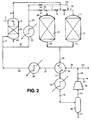
- a technical grade of dimethyl 1,4-cyclohexanedicarboxylate is supplied in line 1, in a first phase of operation, to a vaporiser nozzle 2 located in an upper part of a vaporiser vessel 3 above a bed of packing 4.
- a stream of hot hydrogen-containing gas is supplied to the bottom of vaporiser vessel 3 in line 5.
- a saturated vaporous mixture comprising dimethyl 1,4-cyclohexanedicarboxylate is recovered in line 6 from the top of vaporiser vessel 3.
- the resulting vaporous mixture is mixed with further hot hydrogen-containing gas from line 7 under the control of valve 8.
- the hydrogenation reaction product mixture exits reactor 11 via line 13 and passes through valve 14 to enter line 15.
- the hydrogenation reaction product mixture in line 15 is cooled in heat interchanger 16 and the resulting partially condensed mixture passes on in line 17 through cooler 18 in which it is further cooled.
- the resulting mixture of gas and condensate flows on in line 19 to a gas-liquid separator 20 from which a mixture of methanol and crude 1,4-cyclohexanedimethanol is recovered in line 21.
- the uncondensed gaseous mixture in line 22 comprises unreacted hydrogen together with inert gases and methanol vapour and is compressed by means of compressor 23 to give a compressed gas stream in line 24.
- the compressed recycled gas in line 24 is combined with make-up hydrogen-containing gas from line 25.
- the combined mixture in line 26 is heated by passage through heat exchanger 16 and flows on in line 27 to heater 28 in which its temperature is raised further to a suitable temperature for effecting vaporisation of the dimethyl 1,4-cyclohexanedicarboxylate feed.
- the resulting hot gas in line 29 is then divided into two streams, one being the stream in line 5 and the other being a stream in line 30. This latter stream is heated further in heater 31 to a temperature of about 240°C and passes on by way of line 32, valve 33 and lines 34 and 35 to the bottom end of a second hydrogenation reactor 36 which, in this first phase of operation, is in reactivation mode.
- Reactor 36 contains a charge of hydrogenation catalyst 37.
- the hot gas exiting the top of reactor 36 in line 7 is admixed, as already described above, with the saturated vaporous mixture in line 6 to increase the hydrogen:dimethyl 1,4-cyclohexanedicarboxylate molar ratio therein and to raise its temperature above its dew point, e.g. at least 5°C to 10°C above its dew point.
- the plant also includes lines 38 and 39 and valves 40 and 41 both of which are closed in this phase of operation.
- Line 42 indicates a line by means of which a stream containing any "heavies" collecting in the bottom of vaporiser vessel 3 can be drawn off.
- Reference numeral 43 indicates a purge gas line through which a purge gas stream can be taken in order to limit the build up of inert gases in the circulating gas. Such inert gases may enter the plant in the make up gas stream in line 25.
- valve 33 is shut and valve 41 is opened, while valve 14 is closed and valve 40 is opened.
- hydrogenation reactor 36 with its fresh or reactivated catalyst charge 37 is brought on line, whilst reactor 11 goes into reactivation mode and its partially deactivated charge of catalyst 12 is reactivated.
- the saturated vaporous mixture in line 6 is mixed with hot hydrogen-containing gas from line 10 to form a vaporous feed mixture which flows in line 7 through reactor 36 and its catalyst charge 37.
- the resulting reaction mixture passes by way of lines 35 and 38 through valve 40 to line 15.
- the hot hydrogen-containing gas from line 32 passes through valve 41 to line 39 and then through line 13 to the bottom of hydrogenation reactor 11.
- valves 14, 33, 40 and 41 can be readjusted to switch the flows through hydrogenation reactors 11 and 36 back to those of the first phase of operation.
- the make-up gas in line 25 can be a mixture of hydrogen, optional minor amounts of components such as CO and CO2, and inert gases, such as argon, nitrogen, or methane, containing at least about 70 mole % of hydrogen.
- the make-up gas contains at least 90 mole %, and even more preferably at least 97 mole %, of hydrogen.
- the make-up gas can be produced in any convenient manner, e.g. by partial oxidation or steam reforming of natural gas followed by the water gas shift reaction, and CO2 absorption, followed possibly by methanation of at least some of any residual traces of carbon oxides. Pressure swing absorption can be used if a high purity hydrogen make-up gas is desired.
- the reactors 11 and 36 are each charged with a charge of a heterogeneous hydrogenation catalyst precursor, such as a copper chromite catalyst precursor.
- a heterogeneous hydrogenation catalyst precursor such as a copper chromite catalyst precursor.
- the reactors 11 and 36 are charged with a chromium-free hydrogenation catalyst, such as DRD92/89.
- the catalyst precursor is then reduced carefully following the catalyst supplier's instructions. If the process of EP-A-0301853 is used to reduce a copper chromite precursor, then both beds of catalyst 12 and 37 can be reduced simultaneously. In other cases it may be expedient to reduce the beds 12 and 37 separately.
- hot hydrogen-containing gas is circulated through the plant. When the appropriate feed temperatures to vaporiser vessel 3 and to reactor 11 have been achieved the flow of dimethyl 1,4-cyclohexanedicarboxylate in line 1 is commenced to bring the plant on line in the first phase of operation.
- hot gas from the stream in line 32 can be fed either via valve 51 and line 52 into line 7 and then through reactor 36 or via valve 53 and line 54 into line 10 and then through reactor 11. If reactor 11 is in on line mode with valve a closed and reactor 36 is in reactivation mode, then valve 51 is adjusted so that most of the gas from line 32 flow through valve 51 into reactor 36 and only sufficient gas passes through valve 53 into line 10 to raise the feed temperature to reactor 11 above its dew point. To bring reactor 36 into on line mode valve 9 is closed and valve 8 is opened, whereupon valve 51 is closed somewhat and valve 53 is opened a corresponding amount to cause most of the gas from line 32 to flow through reactor 11 while only sufficient gas passes through valve 51 to satisfy dew point requirements.
- any volatile potential catalyst deactivating materials released in the reaction mode do not pass through the on line catalyst charge and can be recovered in the product stream in line 21.
- preliminary indications are that no such catalyst deactivating materials are released when the unsaturated organic compound being hydrogenated is dimethyl 1,4-cyclohexanedicarboxylate, this may not be the case when other unsaturated organic compounds are being hydrogenated.
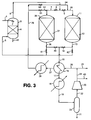
- Figure 3 illustrates a further design of hydrogenation plant in accordance with the invention.
- the direction of gas flow through each of the catalyst beds 12 and 37 during its respective reactivation mode is the same as the direction of flow of vaporous feed mixture during its on line mode.
- the reference numerals used in Figure 3 indicate the same items of equipment that appear in Figure 1 and also in Figure 2.
- the hydrogen-containing gas supplied in line 5 for vaporisation of the incoming dimethyl 1,4-cyclohexanedicarboxylate feed in line 1 is passed first through one of the catalyst beds 12 or 37 in its respective reactivation mode.
- reactor 36 when reactor 36 is in reactivation mode, most of the hot gas in line 29 is fed through valve 51 and line 52 into reactor 36 through catalyst charge 37, and passes out via line 35 and valve 61 to line 5.
- Valves a and 40 are closed and valve 53 is open only so far as is necessary to permit passage of sufficient gas into line 10 to satisfy dew point requirements.
- the vaporous feed mixture in line 6 passes through valve 9 and via line 10 into reactor 11 whose catalyst charge 12 is in on line mode.
- valve 14 The product stream in line 13 flows through valve 14 into line 15, valve 62 being closed.
- valves 8, 40 and 62 are opened, while formerly open valves 9, 14 and 61 are closed.
- Valve 53 is opened somewhat and the gas flow through valve 51 is reduced to the extent necessary for dew point considerations.
- This procedure can be repeated one or more further times as may be expedient bringing the reactors 11 and 36 on line in turn until the reactivation procedure no longer results in the desired increase in catalyst activity or until the plant has to be shut down for maintenance or other reasons, whereupon the catalyst charges 12 and 37 can be discharged and replaced by fresh charges of catalyst or catalyst precursor.
- dimethyl 1,4-cyclohexanedicarboxylate has been chosen as a suitable material with which to exemplify the process of the invention
- the process of the invention is by no means limited in its application to hydrogenation reactions involving dimethyl 1,4-cyclohexanedicarboxylate and may, in fact, be applied to many vapour phase hydrogenation reactions using esters, diesters or lactones as feedstocks, in which involatile hydrogenatable byproducts are formed and deposited on the catalyst surface, for example hydrogenation of dimethyl or diethyl maleate to yield butane-1,4-diol.
- compositions of copper-containing catalysts A and B used in the Examples are listed in Table I.
- the oxygen content of the catalyst has been omitted in each case.
- composition of the technical grade feed was: 34.47 wt% trans -dimethyl 1,4-cyclohexanedicarboxylate, 62.61 wt% cis -dimethyl 1,4-cyclohexanedicarboxylate, 1.50 wt% methyl hydrogen 1,4-cyclohexanedicarboxylate of formula and 0.05 wt% water, with the balance being impurities including di-4-hydroxymethylcyclohexylmethyl ether of formula
- hydrogen gas is separated from the hydrogenation product and is advantageously recycled through the hydrogenation zone.
- the hydrogen recycle stream will contain a quantity of methanol vapour produced by the hydrogenation of dimethyl 1,4-cyclohexanedicarboxylate.
- the vaporous mixture supplied to the hydrogenation zone in a commercial plant will generally contain methanol in addition to hydrogen and an unsaturated organic compound.
- the liquid feed supplied to the vaporiser was supplemented by a quantity of liquid methanol corresponding to the quantity of methanol which would be contained in the recycle hydrogen stream in a commercial plant.
- methanol is added to the experimental liquid feed in a quantity which is substantially equal to the proportionate quantity of methanol which would be present in the experimental recycle stream if the rig were operated under commercial conditions minus the quantity of methanol actually present in the experimental recycle hydrogen stream.
- all parameters such as conversion rates and hourly space velocities are calculated on a methanol free basis.
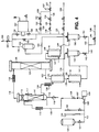
- FIG. 4 An approximately 70 wt% solution of the technical grade of dimethyl 1,4-cyclohexanedicarboxylate in methanol is fed from reservoir 100 by way of valve 101, line 102 and valve 103 to liquid feed pump 104.
- Burette 105 provides a buffer supply whilst burette 106 is fitted with a liquid level controller (not shown) that controls valve 101 so as to ensure that liquid feed is supplied from reservoir 100 to liquid feed pump 104 at a constant head.
- the liquid feed is pumped through non-return valve 107 and isolation valve 108 into line 109, which can be heated by electrical heating tape 110, before the heated liquid enters the upper part of an insulated vaporiser vessel 111 above a bed of 6mm x 6mm glass rings 112.
- a stainless steel demister pad 113 is fitted at the top end of the vaporiser vessel 111.
- a stream of hot hydrogen-containing gas is supplied to the bottom of vaporiser 111 in line 114.
- a liquid drain line 115 fitted with a drain valve 116 enables withdrawal of any unvaporised liquid feed material (e.g. "heavies") from the base of the vaporiser vessel 111.
- the vaporisation of the liquid feed supplied to the vaporiser vessel 111 is assisted by heating tape 117.
- a saturated vaporous mixture comprising dimethyl 1,4-cyclohexanedicarboxylate and hydrogen is recovered in line 118 from the top of vaporiser vessel 111.
- the vaporous mixture is heated by heating tape 119 in order to raise its temperature above the dew point of the mixture prior to entering the top end of hydrogenation reactor 120 which contains a bed of 300 ml (428.1 g) of a pelleted copper chromite hydrogenation catalyst 121.
- the catalyst was catalyst A of Table I. Glass rings are packed in reactor 120 above and below the catalyst bed 121.
- the vaporous mixture passes downward through catalyst bed 121 where conversion of dimethyl 1,4-cyclohexanedicarboxylate to 1,4-cyclohexanedimethanol occurs under adiabatic conditions. Adiabaticity is maintained by electrical heating tapes (not shown) embedded within insulation around reactor 120 under the control of appropriately positioned thermocouples (not shown).
- the overall reaction is mildly exothermic with a general increase in catalyst bed temperature of approximately 1 to 2°C.
- the hydrogenation product mixture exits the hydrogenation reactor 120 in line 122 and is passed through heat exchanger 123 which simultaneously cools the hydrogenation product mixture and heats a supply of hydrogen-containing gas from line 124. Condensation of the bulk of the 1,4-cyclohexanedimethanol in line 122 occurs in heat exchanger 123.
- the gas in line 124 comprises hydrogen-containing gas from line 125 and, optionally, an inert gas or a mixture of inert gases such as nitrogen, argon or methane supplied in line 126.
- the gas in line 125 comprises make-up hydrogen supplied in line 127 and recycle hydrogen supplied in line 128. Make-up hydrogen in line 127 may be supplied to line 125 in either or both of two streams in lines 129 and 130 via a system of pressure controllers 131 to 136 and a mass flow controller 137 from high purity hydrogen cylinders (not shown).
- the heated hydrogen-containing gas from heat exchanger 123 passes on in line 114 and is heated further by electrical heating tape 138 for supply to the vaporiser vessel 111.
- the cooled hydrogenation product from heat exchanger 123 passes on through line 139 to be cooled further in cooler 140 to a temperature near ambient temperature.
- the liquid/vapour mixture from cooler 140 passes on in line 141 to a first knockout pot 142 where liquid hydrogenation product is collected for eventual supply by means of valve 143, line 144 and control valve 145 to product line 146.
- a vaporous mixture comprising hydrogen and uncondensed methanol exits the top of knockout pot 142 in line 147 and is further cooled to a temperature of 10°C in cooler 148.
- the further cooled liquid/vapour mixture from cooler 148 is supplied via line 149 to a second knockout pot 150 wherein condensed methanol is collected for eventual supply through valve 151 and line 152 to product line 146.
- the gas and uncondensed materials from knockout pot 150 are supplied via line 153 through suction pot 154 into line 155 and then through valve 156 to gas recycle compressor 157. Gas is recycled through valve 158 lines 128, 125, 124 and 114 to vaporiser 111.
- a purge gas stream may be bled from the system in line 159 under the control of valve 160.
- Reference numeral 161 indicates a bypass valve.
- the liquid in line 146 was analysed periodically by capillary gas chromatography using a 15 m long, 0.32 mm internal diameter fused silica column coated internally with a 0.25 ⁇ m film of DB wax, a helium flow rate of 2 ml/minute with a gas feed split ratio of 100:1 and a flame ionisation detector.
- the instrument was fitted with a chart recorder having a peak integrator and was calibrated using a commercially available sample of dimethyl 1,4-cyclohexanedicarboxylate of known composition.
- the exit gas was also sampled and analysed by gas chromatography using the same technique. The identities of the peaks were confirmed by comparison of the retention times observed with those of authentic specimens of the materials in question and by mass spectroscopy.
- 1,4-cyclohexanedimethanol dimethyl 1,4-cyclohexanedicarboxylate
- 4-methoxymethyl cyclohexanemethanol di-(4-methoxymethylcyclohexylmethyl) ether
- methanol methanol.
- Operation of the rig was monitored over a period of several weeks. From the results obtained it appeared that over this period dimethyl 1,4-cyclohexanedicarboxylate had been converted in excess of 99%, with a selectivity to 1,4-cyclohexanedimethanol of approximately 98.5% being obtained, the balance being minor by-products.
- Example 3 After further operation of the rig the conversion of dimethyl 1,4-cyclohexanedicarboxylate was found to be 97.53% under the conditions specified for Example 1 in Table II below, the selectivity to 1,4-cyclohexanedimethanol being 96.89%. The operating conditions were subsequently altered to those listed under Example 2 in Table II. Operation of the rig was continued for a number of days over the course of which it was necessary to raise the feed temperature by 3°C in order to maintain the desired conversion of dimethyl 1,4-cyclohexanedicarboxylate. The results observed are listed under Example 3 in Table II.
- Example 4 A further period of continuous operation of the rig ensued during which the activity declined over the course of several weeks, as evidenced by the increase in feed temperature of 6°C, compared with Example 2, necessary to maintain the conversion of dimethyl 1,4-cyclohexanedicarboxylate as near as possible the desired value.
- the results at this time are given under Example 4. Operation was continued for a few days more. Then the conditions were changed to those set out in Table II under Example 5, which are comparable to those specified for Example 1. Compared with Example 1 the conversion had dropped over the intervening period of operation from 97.53% to 85.47%, thus demonstrating that a very significant loss of catalyst activity had occurred.
- the dimethyl 1,4-cyclohexanedicarboxylate feed was then turned off and, after an interval of approximately 3 hours, the feed temperature to reactor 120 was increased to 250°C and hydrogen gas was passed through the reactor 120 at this temperature for 14 hours in order to effect catalyst reactivation.
- the reactor 120 was then returned to the same conditions as those which prevailed immediately prior to the reactivation step.
- the dimethyl 1,4-cyclohexanedicarboxylate conversion immediately after catalyst reactivation had occurred was 91.86% as reported in Example 6, demonstrating that at least partial reactivation had been successfully accomplished. This was confirmed by restoring the operating conditions substantially to those of Example 4.
- the conversion had been increased from 98.61%, as reported in Example 4, to 99.79%, as reported in Example 7, at a feed temperature of 236°C.
- Comparison of Examples 1, 5 and 6 shows that in the interval between Examples 1 and 5 the catalyst had dropped in activity from an arbitrary relative activity value of 100% in Example 1, as measured by conversion of dimethyl 1,4-cyclohexanedicarboxylate, to a relative catalyst activity of 87.63%, measured on the same basis in Example 5. After the reactivation procedure the relative catalyst activity, as reported in Example 6, had been restored to 94.19% of the original value.
- An experimental rig is designed for use in a process intended to be operated in a plant of the type depicted in Figure 1.
- This rig is essentially identified to that of Figure 4 except that reactor 120 is replaced by a pair of reactors in series.
- the same general procedure is followed as described in respect of Examples 1 to 7, with a first reactor on line and maintained under conditions effective to hydrogenate the vaporous feed mixture supplied thereto and a second reactor in standby or reactivation mode with no hydrogenatable material supplied thereto.
- a gradual deactivation of the catalyst charge contained within the first reactor is observed, substantially as exemplified in Examples 1 to 7.
- the vaporous feed mixture supplied thereto is diverted into the second reactor, thereby to allow continuation of the hydrogenation reaction in the second reactor.
- the first reactor is supplied with a hydrogen-containing gas thereby to reactivate the catalyst charge therein.
- the vaporous feed mixture is switched back to the first reactor thereby to allow continuation of the hydrogenation reaction whilst the reactivation procedure is performed on the second reactor.
- the activity of the hydrogenation catalyst in the first reactor is seen to be significantly increased in a manner similar to that reported for a single hydrogenation zone.
- the overall procedure is repeated several times with excellent maintenance of conversion of dimethyl 1,4-cyclohexanedicarboxylate.
Landscapes
- Chemical & Material Sciences (AREA)
- Organic Chemistry (AREA)
- Organic Low-Molecular-Weight Compounds And Preparation Thereof (AREA)
- Low-Molecular Organic Synthesis Reactions Using Catalysts (AREA)
- Glass Compositions (AREA)
- Iron Core Of Rotating Electric Machines (AREA)
Applications Claiming Priority (2)
| Application Number | Priority Date | Filing Date | Title |
|---|---|---|---|
| GB939324786A GB9324786D0 (en) | 1993-12-02 | 1993-12-02 | Process |
| GB9324786 | 1993-12-02 |
Publications (2)
| Publication Number | Publication Date |
|---|---|
| EP0656338A1 true EP0656338A1 (de) | 1995-06-07 |
| EP0656338B1 EP0656338B1 (de) | 1997-12-03 |
Family
ID=10746059
Family Applications (1)
| Application Number | Title | Priority Date | Filing Date |
|---|---|---|---|
| EP94300075A Expired - Lifetime EP0656338B1 (de) | 1993-12-02 | 1994-01-06 | Gasphasenhydrierung von Estern oder Laktonen in Hydroxyverbindungen |
Country Status (9)
| Country | Link |
|---|---|
| US (1) | US5395991A (de) |
| EP (1) | EP0656338B1 (de) |
| JP (1) | JP4050334B2 (de) |
| KR (1) | KR100282969B1 (de) |
| AT (1) | ATE160767T1 (de) |
| DE (1) | DE69407146T2 (de) |
| ES (1) | ES2111845T3 (de) |
| GB (1) | GB9324786D0 (de) |
| TW (1) | TW276247B (de) |
Cited By (1)
| Publication number | Priority date | Publication date | Assignee | Title |
|---|---|---|---|---|
| EP0863119A1 (de) * | 1997-03-03 | 1998-09-09 | Kao Corporation | Verfahren zur Herstellung eines Alkohols |
Families Citing this family (20)
| Publication number | Priority date | Publication date | Assignee | Title |
|---|---|---|---|---|
| US5463143A (en) * | 1994-11-07 | 1995-10-31 | Shell Oil Company | Process for the direct hydrogenation of wax esters |
| US5475159A (en) * | 1994-11-07 | 1995-12-12 | Shell Oil Company | Process for the direct hydrogenation of methyl esters |
| US5475160A (en) * | 1994-11-07 | 1995-12-12 | Shell Oil Company | Process for the direct hydrogenation of triglycerides |
| US5536889A (en) * | 1995-09-29 | 1996-07-16 | Shell Oil Company | Process for the two-stage hydrogenation of methyl esters |
| US6455742B1 (en) | 1999-09-02 | 2002-09-24 | Wisconsin Alumni Research Foundation | Method for catalytically reducing carboxylic acid groups to hydroxyl groups in hydroxycarboxylic acids |
| BR0315969B1 (pt) * | 2002-11-01 | 2013-03-19 | processo para preparaÇço de 1,3-propanodiol. | |
| US7084180B2 (en) * | 2004-01-28 | 2006-08-01 | Velocys, Inc. | Fischer-tropsch synthesis using microchannel technology and novel catalyst and microchannel reactor |
| US6919489B1 (en) | 2004-03-03 | 2005-07-19 | Eastman Chemical Company | Process for a cyclohexanedimethanol using raney metal catalysts |
| PL2200958T3 (pl) * | 2007-08-31 | 2016-04-29 | Basf Se | Sposób wytwarzania 1,2-propanodiolu drogą uwodorniania glicerolu w dwustopniowej kaskadzie reaktorów |
| US8581010B2 (en) * | 2011-05-04 | 2013-11-12 | John E. Stauffer | Formation of ethanol from methanol |
| US9108895B2 (en) | 2012-10-26 | 2015-08-18 | Eastman Chemical Company | Promoted ruthenium catalyst for the improved hydrogenation of carboxylic acids to the corresponding alcohols |
| US9115155B1 (en) | 2014-03-20 | 2015-08-25 | Eastman Chemical Company | Low-pressure synthesis of cyclohexanedimethanol and derivatives |
| WO2016025214A1 (en) * | 2014-08-15 | 2016-02-18 | Exxonmobil Chemical Patents Inc. | Process and system for making cyclohexanone |
| US10293304B2 (en) | 2015-07-14 | 2019-05-21 | John E. Stauffer | Carbon dioxide recovery using an absorption column in combination with osmotic filters |
| US10493397B2 (en) | 2015-07-14 | 2019-12-03 | John E. Stauffer | Carbon dioxide recovery |
| US10040737B2 (en) | 2015-07-14 | 2018-08-07 | John E. Stauffer | Methanol production from methane and carbon dioxide |
| KR102223388B1 (ko) | 2017-09-29 | 2021-03-04 | 한화솔루션 주식회사 | 사이클로헥산 디카르복실산 수소화 반응용 루테늄-백금-주석 촉매의 제조방법 및 이에 의해 제조된 촉매를 이용한 사이클로헥산 디메탄올 (chdm)의 제조방법 |
| JP6786054B2 (ja) * | 2017-12-18 | 2020-11-18 | 株式会社豊田中央研究所 | メタンの製造装置及びそれを用いたメタンの製造方法 |
| KR102188755B1 (ko) | 2017-12-22 | 2020-12-08 | 한화솔루션 주식회사 | 높은 트랜스 함량을 갖는 사이클로헥산 디메탄올 제조방법 및 이에 의해 제조된 사이클로헥산 디메탄올 |
| KR102238548B1 (ko) | 2017-12-29 | 2021-04-08 | 한화솔루션 주식회사 | 카본이 코팅된 실리카-알루미나 담체에 담지된 귀금속-전이금속 복합 촉매 및 이의 제조방법 |
Citations (2)
| Publication number | Priority date | Publication date | Assignee | Title |
|---|---|---|---|---|
| EP0143634A2 (de) * | 1983-11-29 | 1985-06-05 | DAVY McKEE (LONDON) LIMITED | Verfahrenzur Herstellung von Butan-1,4-diol |
| WO1986003189A1 (en) * | 1984-11-21 | 1986-06-05 | Davy Mckee (London) Limited | Process for the production of butane-1,4-diol |
Family Cites Families (45)
| Publication number | Priority date | Publication date | Assignee | Title |
|---|---|---|---|---|
| US2105664A (en) * | 1930-04-17 | 1938-01-18 | Du Pont | Catalytic hydrogenation of hydroaromatic carboxylic acids and their esters |
| US2137407A (en) * | 1931-05-11 | 1938-11-22 | Du Pont | Catalytic hydrogenation process |
| US2091800A (en) * | 1931-09-15 | 1937-08-31 | Rohm & Haas | Method of hydrogenating esters |
| US2079414A (en) * | 1932-08-20 | 1937-05-04 | Du Pont | Process for producing alcohols from esters of nonaromatic carboxylic acids |
| US2040944A (en) * | 1933-09-22 | 1936-05-19 | Du Pont | Process for producing polyhydroxy alcohols |
| US2755317A (en) * | 1952-11-10 | 1956-07-17 | Universal Oil Prod Co | Hydrogenation of benzene to cyclohexane |
| US2818393A (en) * | 1953-05-05 | 1957-12-31 | Kellogg M W Co | Method of preparing a catalyst |
| US2830095A (en) * | 1953-05-07 | 1958-04-08 | Olin Mathieson | Production of ethylene chlorohydrin |
| BE592181A (de) * | 1955-12-22 | |||
| US2884450A (en) * | 1956-04-20 | 1959-04-28 | Du Pont | Hydrogenation of unsaturated dilactones to 1,8-octanedioic acids and 1,8-octanediolswith copper chromite catalysts |
| US2917549A (en) * | 1958-01-07 | 1959-12-15 | Eastman Kodak Co | Preparation of trans-1,4-cyclohexanedimethanol |
| NL260833A (de) * | 1960-02-09 | |||
| DE1144703B (de) * | 1960-10-06 | 1963-03-07 | Eastman Kodak Co | Verfahren zur Herstellung von Alkoholen durch katalytische Hydrierung von Estern |
| FR1276722A (fr) * | 1960-10-11 | 1961-11-24 | Eastman Kodak Co | Procédé de préparation d'un catalyseur en vue de la réduction des esters en alcools |
| NL292315A (de) * | 1962-05-05 | |||
| CH438269A (it) * | 1963-05-10 | 1967-06-30 | Snam Spa | Processo di idrogenazione di composti acetilenici miscibili con acqua a composti etilenici |
| US3334149A (en) * | 1964-07-21 | 1967-08-01 | Eastman Kodak Co | Plural stage hydrogenation of dialkyl terephthalate using palladium and then copper chromite |
| US4052467A (en) * | 1967-11-08 | 1977-10-04 | Phillips Petroleum Company | Catalytic reduction of aldehydes to alcohols |
| GB1454440A (en) * | 1974-10-03 | 1976-11-03 | Ucb Sa | Process for the production of butane-1,4-diol from but-2-ene- 1,4-dioic acid |
| GB1464263A (en) * | 1974-12-03 | 1977-02-09 | Ucb Sa | Production of butane-1,4-diol |
| US4172961A (en) * | 1975-08-08 | 1979-10-30 | Denka Chemical Corporation | Production of 1,4-butanediol |
| US4032458A (en) * | 1975-08-08 | 1977-06-28 | Petro-Tex Chemical Corporation | Production of 1,4-butanediol |
| DE2719867A1 (de) * | 1977-05-04 | 1978-11-09 | Bayer Ag | Verfahren zur herstellung von butandiol-1,4 |
| DE2845905C3 (de) * | 1978-10-21 | 1983-05-26 | Chemische Werke Hüls AG, 4370 Marl | Verfahren zur kontinuierlichen Herstellung von Butandiol-1,4 |
| DE3106819A1 (de) * | 1981-02-24 | 1982-09-09 | Basf Ag, 6700 Ludwigshafen | Verfahren zur herstellung von 1,4-butandiol |
| IT1190783B (it) * | 1981-04-29 | 1988-02-24 | Davy Mckee Oil & Chem | Processo per l'idrogenolisi di esteri di acidi carbossilici |
| GB8514002D0 (en) * | 1985-06-04 | 1985-07-10 | Davy Mckee Ltd | Process |
| GB8514001D0 (en) * | 1985-06-04 | 1985-07-10 | Davy Mckee Ltd | Process |
| US4652685A (en) * | 1985-11-15 | 1987-03-24 | General Electric Company | Hydrogenation of lactones to glycols |
| DE3610698A1 (de) * | 1986-03-29 | 1987-10-01 | Henkel Kgaa | Katalysator und verfahren zur katalytischen hydrierung von fettsaeuremethylestern im festbett |
| WO1988000937A1 (en) * | 1986-08-01 | 1988-02-11 | Davy Mckee (London) Limited | Process for the co-production of butane-1,4-diol and gamma-butyrolactone |
| GB8717989D0 (en) * | 1987-07-29 | 1987-09-03 | Davy Mckee Ltd | Catalyst |
| KR970009560B1 (ko) * | 1987-08-03 | 1997-06-14 | 이스트만 코닥 컴퍼니 | 카보닐을 함유하는 화합물의 저압 촉매수소화 및 이에 관한 촉매 |
| US4837368A (en) * | 1988-02-01 | 1989-06-06 | Eastman Kodak Company | Low pressure catalytic hydrogenation of carbonyl-containing compounds and supported catalysts therefor |
| US4999090A (en) * | 1988-04-10 | 1991-03-12 | Towa Chemical Industry Co., Ltd. | Process for preparing trans-1,4-cyclohexanedimethanol and powder of the same |
| US5185476A (en) * | 1988-07-15 | 1993-02-09 | Eastman Kodak Company | Low pressure catalytic hydrogenation of carbonyl-containing compounds and supported catalysts therefor |
| DE3843956A1 (de) * | 1988-12-24 | 1990-06-28 | Huels Chemische Werke Ag | Verfahren zur herstellung von aliphatischen und cycloaliphatischen diolen durch katalytische hydrierung von dicarbonsaeureestern |
| KR930006046B1 (ko) * | 1988-12-28 | 1993-07-03 | 미쓰비시 레이욘 가부시키가이샤 | 폴리에스테르 공중합체 |
| AU641630B2 (en) * | 1989-01-17 | 1993-09-30 | Davy Mckee (London) Limited | Process for the production of fatty alcohols |
| US4929777A (en) * | 1989-02-13 | 1990-05-29 | Eastman Kodak Company | Catalyst compositions and the use thereof in the hydrogenation of carboxylic acid esters |
| GB8917862D0 (en) * | 1989-08-04 | 1989-09-20 | Davy Mckee London | Process |
| US5142067A (en) * | 1989-12-21 | 1992-08-25 | Union Carbide Chemicals & Plastics Technology Corporation | Hydrogenation with Cu-Al-X catalysts |
| US5191091A (en) * | 1989-12-21 | 1993-03-02 | Union Carbide Chemicals & Plastics Technology Corporation | Hydrogenation with Cu-Al catalysts |
| GB9025708D0 (en) * | 1990-11-27 | 1991-01-09 | Unilever Plc | Fatty ester hydrogenation |
| DE4141199A1 (de) * | 1991-12-13 | 1993-06-17 | Sued Chemie Ag | Chromfreier katalysator fuer die hydrierung von organischen verbindungen, die die carbonylfunktionen enthalten |
-
1993
- 1993-12-02 GB GB939324786A patent/GB9324786D0/en active Pending
- 1993-12-30 US US08/175,545 patent/US5395991A/en not_active Expired - Lifetime
- 1993-12-31 TW TW082111217A patent/TW276247B/zh not_active IP Right Cessation
-
1994
- 1994-01-06 ES ES94300075T patent/ES2111845T3/es not_active Expired - Lifetime
- 1994-01-06 DE DE69407146T patent/DE69407146T2/de not_active Expired - Lifetime
- 1994-01-06 EP EP94300075A patent/EP0656338B1/de not_active Expired - Lifetime
- 1994-01-06 KR KR1019940000133A patent/KR100282969B1/ko not_active Expired - Lifetime
- 1994-01-06 AT AT94300075T patent/ATE160767T1/de not_active IP Right Cessation
- 1994-01-10 JP JP00080094A patent/JP4050334B2/ja not_active Expired - Fee Related
Patent Citations (2)
| Publication number | Priority date | Publication date | Assignee | Title |
|---|---|---|---|---|
| EP0143634A2 (de) * | 1983-11-29 | 1985-06-05 | DAVY McKEE (LONDON) LIMITED | Verfahrenzur Herstellung von Butan-1,4-diol |
| WO1986003189A1 (en) * | 1984-11-21 | 1986-06-05 | Davy Mckee (London) Limited | Process for the production of butane-1,4-diol |
Cited By (4)
| Publication number | Priority date | Publication date | Assignee | Title |
|---|---|---|---|---|
| EP0863119A1 (de) * | 1997-03-03 | 1998-09-09 | Kao Corporation | Verfahren zur Herstellung eines Alkohols |
| US6049013A (en) * | 1997-03-03 | 2000-04-11 | Kao Corporation | Method for producing alcohol |
| CN1080250C (zh) * | 1997-03-03 | 2002-03-06 | 花王株式会社 | 生产醇的方法 |
| MY119914A (en) * | 1997-03-03 | 2005-08-30 | Kao Corp | Method for producing alcohol. |
Also Published As
| Publication number | Publication date |
|---|---|
| ATE160767T1 (de) | 1997-12-15 |
| KR100282969B1 (ko) | 2001-04-02 |
| TW276247B (de) | 1996-05-21 |
| EP0656338B1 (de) | 1997-12-03 |
| GB9324786D0 (en) | 1994-01-19 |
| ES2111845T3 (es) | 1998-03-16 |
| KR950017897A (ko) | 1995-07-20 |
| DE69407146D1 (de) | 1998-01-15 |
| JP4050334B2 (ja) | 2008-02-20 |
| US5395991A (en) | 1995-03-07 |
| JPH07188077A (ja) | 1995-07-25 |
| DE69407146T2 (de) | 1998-04-16 |
Similar Documents
| Publication | Publication Date | Title |
|---|---|---|
| EP0656340B1 (de) | Verfahren zur Herstellung von Hydroxyverbindungen durch Hydrierung von sauerstoffenthaltenden Verbindungen | |
| US5395991A (en) | Process for the production of alcohols and diols | |
| EP0656337B1 (de) | Verfahren zur Herstellung von 1,4-Cyclohexandimethanol | |
| EP0656339B1 (de) | Verfahren zur Herstellung von vorwiegend als Trans-Isomere vorhandenem Cyclohexandimethanol | |
| EP0656335B1 (de) | Verfahren zur Herstellung von Hydroxyverbindungen durch Hydrierung von sauerstoffenthaltenden Verbindungen | |
| HK1001727B (en) | Process for the production of 1,4-cyclohexanedimethanol | |
| US5395990A (en) | Process for the production of alcohols and diols | |
| EP0656334B1 (de) | Verfahren zur Herstellung von vorwiegend als Trans-Isomere vorhandenem Cyclohexandimethanol | |
| EP0656341B1 (de) | Verfahren zur Herstellung von Cyclohexandimethanol | |
| MXPA94009271A (en) | Process for the production of 1,4-cyclohexanedimethanol |
Legal Events
| Date | Code | Title | Description |
|---|---|---|---|
| PUAI | Public reference made under article 153(3) epc to a published international application that has entered the european phase |
Free format text: ORIGINAL CODE: 0009012 |
|
| AK | Designated contracting states |
Kind code of ref document: A1 Designated state(s): AT BE CH DE DK ES FR GB GR IE IT LI LU MC NL PT SE |
|
| 17P | Request for examination filed |
Effective date: 19950718 |
|
| 17Q | First examination report despatched |
Effective date: 19960812 |
|
| GRAG | Despatch of communication of intention to grant |
Free format text: ORIGINAL CODE: EPIDOS AGRA |
|
| GRAH | Despatch of communication of intention to grant a patent |
Free format text: ORIGINAL CODE: EPIDOS IGRA |
|
| GRAH | Despatch of communication of intention to grant a patent |
Free format text: ORIGINAL CODE: EPIDOS IGRA |
|
| GRAA | (expected) grant |
Free format text: ORIGINAL CODE: 0009210 |
|
| AK | Designated contracting states |
Kind code of ref document: B1 Designated state(s): AT BE CH DE DK ES FR GB GR IE IT LI LU MC NL PT SE |
|
| PG25 | Lapsed in a contracting state [announced via postgrant information from national office to epo] |
Ref country code: LI Free format text: LAPSE BECAUSE OF FAILURE TO SUBMIT A TRANSLATION OF THE DESCRIPTION OR TO PAY THE FEE WITHIN THE PRESCRIBED TIME-LIMIT Effective date: 19971203 Ref country code: GR Free format text: LAPSE BECAUSE OF FAILURE TO SUBMIT A TRANSLATION OF THE DESCRIPTION OR TO PAY THE FEE WITHIN THE PRESCRIBED TIME-LIMIT Effective date: 19971203 Ref country code: DK Free format text: LAPSE BECAUSE OF NON-PAYMENT OF DUE FEES Effective date: 19971203 Ref country code: CH Free format text: LAPSE BECAUSE OF FAILURE TO SUBMIT A TRANSLATION OF THE DESCRIPTION OR TO PAY THE FEE WITHIN THE PRESCRIBED TIME-LIMIT Effective date: 19971203 Ref country code: AT Free format text: LAPSE BECAUSE OF FAILURE TO SUBMIT A TRANSLATION OF THE DESCRIPTION OR TO PAY THE FEE WITHIN THE PRESCRIBED TIME-LIMIT Effective date: 19971203 |
|
| REF | Corresponds to: |
Ref document number: 160767 Country of ref document: AT Date of ref document: 19971215 Kind code of ref document: T |
|
| REG | Reference to a national code |
Ref country code: CH Ref legal event code: EP |
|
| ITF | It: translation for a ep patent filed | ||
| PG25 | Lapsed in a contracting state [announced via postgrant information from national office to epo] |
Ref country code: LU Free format text: LAPSE BECAUSE OF NON-PAYMENT OF DUE FEES Effective date: 19980106 |
|
| REF | Corresponds to: |
Ref document number: 69407146 Country of ref document: DE Date of ref document: 19980115 |
|
| PG25 | Lapsed in a contracting state [announced via postgrant information from national office to epo] |
Ref country code: IE Free format text: LAPSE BECAUSE OF NON-PAYMENT OF DUE FEES Effective date: 19980203 |
|
| PG25 | Lapsed in a contracting state [announced via postgrant information from national office to epo] |
Ref country code: SE Free format text: LAPSE BECAUSE OF FAILURE TO SUBMIT A TRANSLATION OF THE DESCRIPTION OR TO PAY THE FEE WITHIN THE PRESCRIBED TIME-LIMIT Effective date: 19980303 Ref country code: PT Free format text: LAPSE BECAUSE OF FAILURE TO SUBMIT A TRANSLATION OF THE DESCRIPTION OR TO PAY THE FEE WITHIN THE PRESCRIBED TIME-LIMIT Effective date: 19980303 |
|
| ET | Fr: translation filed | ||
| REG | Reference to a national code |
Ref country code: ES Ref legal event code: FG2A Ref document number: 2111845 Country of ref document: ES Kind code of ref document: T3 |
|
| REG | Reference to a national code |
Ref country code: CH Ref legal event code: PL |
|
| PG25 | Lapsed in a contracting state [announced via postgrant information from national office to epo] |
Ref country code: MC Free format text: LAPSE BECAUSE OF NON-PAYMENT OF DUE FEES Effective date: 19980731 |
|
| PLBE | No opposition filed within time limit |
Free format text: ORIGINAL CODE: 0009261 |
|
| STAA | Information on the status of an ep patent application or granted ep patent |
Free format text: STATUS: NO OPPOSITION FILED WITHIN TIME LIMIT |
|
| 26N | No opposition filed | ||
| REG | Reference to a national code |
Ref country code: GB Ref legal event code: IF02 |
|
| PGFP | Annual fee paid to national office [announced via postgrant information from national office to epo] |
Ref country code: FR Payment date: 20101221 Year of fee payment: 18 |
|
| PGFP | Annual fee paid to national office [announced via postgrant information from national office to epo] |
Ref country code: NL Payment date: 20110117 Year of fee payment: 18 Ref country code: IT Payment date: 20110118 Year of fee payment: 18 |
|
| PGFP | Annual fee paid to national office [announced via postgrant information from national office to epo] |
Ref country code: BE Payment date: 20110221 Year of fee payment: 18 Ref country code: ES Payment date: 20110117 Year of fee payment: 18 |
|
| BERE | Be: lapsed |
Owner name: *EASTMAN CHEMICAL CY Effective date: 20120131 |
|
| REG | Reference to a national code |
Ref country code: NL Ref legal event code: V1 Effective date: 20120801 |
|
| REG | Reference to a national code |
Ref country code: FR Ref legal event code: ST Effective date: 20120928 |
|
| PG25 | Lapsed in a contracting state [announced via postgrant information from national office to epo] |
Ref country code: IT Free format text: LAPSE BECAUSE OF NON-PAYMENT OF DUE FEES Effective date: 20120106 |
|
| PG25 | Lapsed in a contracting state [announced via postgrant information from national office to epo] |
Ref country code: BE Free format text: LAPSE BECAUSE OF NON-PAYMENT OF DUE FEES Effective date: 20120131 Ref country code: FR Free format text: LAPSE BECAUSE OF NON-PAYMENT OF DUE FEES Effective date: 20120131 |
|
| PG25 | Lapsed in a contracting state [announced via postgrant information from national office to epo] |
Ref country code: NL Free format text: LAPSE BECAUSE OF NON-PAYMENT OF DUE FEES Effective date: 20120801 |
|
| PGFP | Annual fee paid to national office [announced via postgrant information from national office to epo] |
Ref country code: GB Payment date: 20121228 Year of fee payment: 20 |
|
| PGFP | Annual fee paid to national office [announced via postgrant information from national office to epo] |
Ref country code: DE Payment date: 20130131 Year of fee payment: 20 |
|
| REG | Reference to a national code |
Ref country code: ES Ref legal event code: FD2A Effective date: 20130705 |
|
| PG25 | Lapsed in a contracting state [announced via postgrant information from national office to epo] |
Ref country code: ES Free format text: LAPSE BECAUSE OF NON-PAYMENT OF DUE FEES Effective date: 20120107 |
|
| REG | Reference to a national code |
Ref country code: DE Ref legal event code: R071 Ref document number: 69407146 Country of ref document: DE |
|
| REG | Reference to a national code |
Ref country code: DE Ref legal event code: R071 Ref document number: 69407146 Country of ref document: DE |
|
| REG | Reference to a national code |
Ref country code: GB Ref legal event code: PE20 Expiry date: 20140105 |
|
| PG25 | Lapsed in a contracting state [announced via postgrant information from national office to epo] |
Ref country code: GB Free format text: LAPSE BECAUSE OF EXPIRATION OF PROTECTION Effective date: 20140105 Ref country code: DE Free format text: LAPSE BECAUSE OF EXPIRATION OF PROTECTION Effective date: 20140108 |