EP0656530A1 - Wägeapparat mit Vielfachpunktmesszelle - Google Patents
Wägeapparat mit Vielfachpunktmesszelle Download PDFInfo
- Publication number
- EP0656530A1 EP0656530A1 EP94308839A EP94308839A EP0656530A1 EP 0656530 A1 EP0656530 A1 EP 0656530A1 EP 94308839 A EP94308839 A EP 94308839A EP 94308839 A EP94308839 A EP 94308839A EP 0656530 A1 EP0656530 A1 EP 0656530A1
- Authority
- EP
- European Patent Office
- Prior art keywords
- floor
- cells
- signals
- vibration
- weight
- Prior art date
- Legal status (The legal status is an assumption and is not a legal conclusion. Google has not performed a legal analysis and makes no representation as to the accuracy of the status listed.)
- Granted
Links
- 238000005303 weighing Methods 0.000 title claims abstract description 76
- 230000035945 sensitivity Effects 0.000 claims abstract description 72
- 238000001514 detection method Methods 0.000 claims abstract description 15
- 238000006073 displacement reaction Methods 0.000 claims description 12
- 238000000034 method Methods 0.000 description 23
- 230000008569 process Effects 0.000 description 19
- 238000012937 correction Methods 0.000 description 13
- 238000001914 filtration Methods 0.000 description 10
- 230000000694 effects Effects 0.000 description 9
- 230000006641 stabilisation Effects 0.000 description 8
- 238000011105 stabilization Methods 0.000 description 8
- 238000012545 processing Methods 0.000 description 7
- 238000010586 diagram Methods 0.000 description 5
- 229910009447 Y1-Yn Inorganic materials 0.000 description 3
- 230000005484 gravity Effects 0.000 description 3
- 230000002411 adverse Effects 0.000 description 2
- 230000002238 attenuated effect Effects 0.000 description 2
- 238000013461 design Methods 0.000 description 2
- 238000012986 modification Methods 0.000 description 2
- 230000004048 modification Effects 0.000 description 2
- 230000035939 shock Effects 0.000 description 2
- 230000000087 stabilizing effect Effects 0.000 description 2
- 238000011144 upstream manufacturing Methods 0.000 description 2
- 238000012935 Averaging Methods 0.000 description 1
- 239000000956 alloy Substances 0.000 description 1
- 230000008859 change Effects 0.000 description 1
- 230000007613 environmental effect Effects 0.000 description 1
- 230000006870 function Effects 0.000 description 1
- 239000011159 matrix material Substances 0.000 description 1
- 238000005259 measurement Methods 0.000 description 1
- 230000004044 response Effects 0.000 description 1
Images




Classifications
-
- G—PHYSICS
- G01—MEASURING; TESTING
- G01G—WEIGHING
- G01G23/00—Auxiliary devices for weighing apparatus
- G01G23/06—Means for damping oscillations, e.g. of weigh beams
- G01G23/10—Means for damping oscillations, e.g. of weigh beams by electric or magnetic means
-
- G—PHYSICS
- G01—MEASURING; TESTING
- G01G—WEIGHING
- G01G3/00—Weighing apparatus characterised by the use of elastically-deformable members, e.g. spring balances
- G01G3/12—Weighing apparatus characterised by the use of elastically-deformable members, e.g. spring balances wherein the weighing element is in the form of a solid body stressed by pressure or tension during weighing
- G01G3/14—Weighing apparatus characterised by the use of elastically-deformable members, e.g. spring balances wherein the weighing element is in the form of a solid body stressed by pressure or tension during weighing measuring variations of electrical resistance
- G01G3/1414—Arrangements for correcting or for compensating for unwanted effects
Definitions
- This invention relates to a weighing machine of the so-called multi-point cell type, characterized as having a weighing table supported by a plurality of scale cells in which the weight signals from these scale cells are added to measure the weight of a target object placed on the weighing table.
- this invention relates to such a machine capable of high-speed weighing.
- Weighing machines of the multi-point cell type have been in use for measuring the weight of a large or heavy target object, such as an automobile, by supporting a weighing table by a plurality of weighing cells and adding the weight signals outputted from the individual cells.
- weighing machines of the multiple-point cell type are advantageous because the size of the weighing table can be made larger since many weighing cells of about the same size can be used to support it.
- the scale cells are typically comprised of a deformable body with strain gauges attached thereon.
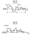
- the stabilization time S it takes, however, a significantly long time (referred to as the stabilization time S), say, of about 200msec until such a filtered signal becomes stabilized, and this has indeed been a source of problem in the attempt to achieve high-speed weighing.
- the stabilization time S it has been known to carry out a stabilization routine on weight data in order to speed up a weighing process. For example, if there is a set of time-sequenced signal values a1, a2, a3, a4, a5, a6, ...
- a final equilibrium value to which the signal values are expected to converge may be predicted by first taking the average of a1, a2 and a3, next taking the average of a2, a3 and a4, then taking the average of a3, a4 and a5, and so forth.
- a partially stabilized value can be obtained within a shorter time period, say, of about 150msec without waiting for the full stabilization time S.
- the overall weighing efficiency is thereby improved if such partially stabilized values are used as the stabilized weight value.
- the floor vibrations pick up the effects of environmental vibrations (to be referred to simply as "the floor vibrations") such as vibrations of the ground, building, floor and/or table on which they are set.
- the floor vibrations have frequencies lower than those of the weighing system.
- they are passed through the digital filter 27 and added to the weight signals which are outputted, as shown in Fig. 15. If the averaging method described above were applied to this situation by considering time-sequenced signal values b1, b2, b3, b4, b5, b6, ... , the convergence would be slow because of the effects of these low-frequency components.
- the cutoff frequency of the digital filters 27 is lowered in an attempt to reduce the effects of the floor vibrations, however, this will tend to increase the stabilization time S, adversely affecting the capability of the system as a whole.
- a multi-point cell type weighing machine may be characterized not only as supporting a weighing table by a plurality of scale cells and being adapted to add weight signals from the individual cells to thereby obtain a sum signal representing the weight of an object placed on the weighing table, but also as comprising floor vibration detecting cells set on the same floor as the scale cells, floor vibration adjusting means for outputting a corrected signal by adjusting the weight signals or the sum signal with the vibration components of vibration detection signals outputted from the floor vibration detecting cells to thereby correcting errors in the weight signals due to the floor vibrations, sensitivity calculating means for calculating output sensitivity ratio among the scale cells from outputted values from the individual weighing cells as a standard weight is placed sequentially at more different positions on the weighing table than the number of the scale cells, and sensitivity correcting means for correcting the aforementioned weight signal based on the output sensitivity ratio.
- one of the floor vibration detecting cells is positioned near each of the scale cells.
- a plurality of floor vibration detecting cells are provided and the floor vibration adjusting means includes floor vibration calculating means for detecting vibration mode of the floor from the vibration components of the floor vibration detection signals outputted from the plurality of floor vibration detecting cells and thereby calculating vertical displacements of the floor at the positions of the scale cells and floor vibration correcting means for generating a corrected signal by subtracting components of the floor vibrations from the weight signals.
- each of the scale cells has one of the floor vibration detecting cells at a nearby position, each pair of mutually near cells may be considered to vibrate in the same mode.
- the effects of the floor vibrations can be immediately removed by directly subtracting the corresponding floor vibration detecting signal from each weight signal.
- the mode of vibrations of the floor is detected from the vibration components of the floor vibration detection signals outputted from the plurality of floor vibration detecting cells and the vertical displacement of the floor is calculated therefrom where each of the scale cells is positioned.
- the weight signals are corrected thereby and corrected signals are generated and added together.
- weight signals can be corrected accurately even in a situation where the floor is vibrating differently at the position of a scale cell and that of the corresponding floor vibration detecting cell. Since the limitations on where to set the floor vibration detecting cells become less stringent in this case, there is an increased degree of freedom in the design choice of the weighing machine. If a single floor vibration detecting cell is used at a center, on the other hand, the structure of the weighing machine becomes simpler.
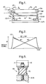
- a multi-point cell type weighing machine uses a weighing conveyor 10 serving as a weighing table, with a belt 10c stretched between a drive roller 10a, rotationally driven by a drive motor (not shown), and a follower roller 10b.
- Bearings 10d and 10e for the two rollers 10a and 10b are supported by a horizontally extending supporting plate 15 through vertically extending members 10f and 10g.
- the supporting plate 15 is in turn supported by a pair of scale cells 1 and 2 at its front and back positions.
- These scale cells 1 and 2 may be of the type comprising a deformable member having strain gauges attached thereto.
- a target object 20 to be weighed is arranged to be brought onto the weighing conveyor 10 from a delivery conveyor 40 disposed on the upstream side such that its weight can be measured by the pair of scale cells 1 and 2 while it is transported in the direction of arrow X on the weighing conveyor 10.
- Weight signals W1 and W2 indicative of the weight values measured by and outputted from the two scale cells 1 and 2 respectively, will generally look as shown in Fig. 2, changing with time as the target object 20 is transported, and its weight can be obtained from the sum W1+W2 of these two weight signals W1 and W2.
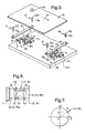
- the scale cells 1 and 2 are each disposed such that their axial lines 1c and 2c connecting their fixed ends 1a and 2a respectively with their free ends 1b and 2b are both perpendicular to the direction X of transportation of the object 20.
- These fixed ends 1a and 2a are supported by a base 5 (serving as "the floor F") respectively through fastening devices 3 and 4 to form cantilevers.
- Horizontal arms 8 and 9 are attached to the free ends 1b and 2b through fastening devices 3 and 4, respectively.
- Numerals 11, 12, 13 and 14 indicate holders for supporting the supporting plate 15 thereon.
- Each of the horizontally maintained arms 8 and 9 supports two or more (two in the example shown in Fig. 3) of these holders, each comprising a conically shaped member 11b, 12b, 13b or 14b fastened by a bolt 11a, 12a, 13a or 14a.
- These conically shaped members 11b, 12b, 13b and 14b are pointed at one end and the supporting plate 15 is supported from below by these pointed ends at its four corners.
- Two floor vibration detecting cells 161 and 162 are disposed near the scale cells 1 and 2, respectively, in the direction X of transportation. These two floor vibration detecting cells 161 and 162 are structured similarly to the scale cells 1 and 2 described above, each having one of its ends fastened through a fastening device 171 or 172 to the same base 5 and having a weight 181 or 182 fastened to the other end.
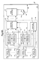
- the weighing machine is provided with a signal processing unit as schematically shown in Fig. 4A, including a CPU (such as a digital signal processor DSP) 25 shown more in detail in Fig. 4B.
- a CPU such as a digital signal processor DSP
- weight signals outputted from the scale cells 1 and 2 are amplified by amplifiers 22
- floor vibration detection signals outputted from the floor vibration detecting cells 161 and 162 are amplified by amplifiers 23, and these amplified signals are all inputted into a multiplexer 24, which is controlled by the CPU 25 through control signals c to selectively output these signals to an A/D converter 26.
- the digital weight signals will be indicated as W1 and W2
- the digital floor vibration detection signals will be indicated as Y1 and Y2.
- the signals W1, W2, Y1 and Y2 are received by the CPU 25, they are individually passed through a digital filtering means 28 having the characteristics of a low pass filter with cutoff frequency higher than 10Hz-20Hz for carrying out a filtering process, for example, by a convolution calculation of a known kind.
- the filtered signals outputted from the digital filtering means 28 will be denoted FW1, FW2, FY1 and FY2, respectively, as shown in Fig. 4B.
- a sensitivity adjusting process is carried out next on the filtered signals FW1, FW2, FY1 and FY2 by a sensitivity adjusting means 52 which includes sensitivity calculating means 54 and sensitivity correcting means 56.
- the sensitivity calculating means 54 calculates the output sensitivity ratio between the scale cell 1 and the floor vibration detecting cell 161 and the output sensitivity ratio between the scale cell 2 and the floor vibration detecting cell 162 on the basis of the differences in the spring constant and the load weight (including the tare) between the scale cell 1 (or 2) and the floor vibration detecting cell 161 (or 162).
- the sensitivity correcting means 56 corrects the filtered signals FY1 and FY2 from the floor vibration detecting cells 161 and 162 on the basis of the output sensitivity ratios thus calculated to output sensitivity-corrected signals SY1 and SY2.
- the filtered signals FY1 and FY2 may be corrected on the basis of these known ratios.
- corrections may similarly be effected on the filtered signals FW1 and FW2 from the scale cells 1 and 2 on the basis of the calculated or known output sensitivity ratios.
- the CPU 25 makes uses of the floor vibration adjusting means 42 and 44 to correct the effects of the floor vibrations on the weight signals to obtain vibration-corrected signals V1 and V2.
- the span-adjustment means 60 for correcting the output sensitivity ratio between the scale cells 1 and 2 when the machine is shipped from the factory or installed at the site of its operation.
- the span-adjustment means 60 is provided with a sensitivity calculating means 62, a sensitivity correcting means 64 and a mode-switching means 68.
- the mode-switching means 68 is for switching the mode of operation of the machine in response to a command from outside between a normal weighing mode and an output sensitivity ratio calculating mode.
- the machine In Fig. 4B, the machine is in the normal weighing mode with software switches 63 in the OFF positions as shown. If the switches 63 are in the ON positions, the machine will be in the output sensitivity calculating mode.
- the machine In general, the machine is switched to the output sensitivity calculating mode to calculate output sensitivity ratios when it is delivered from the factory or installed at a site but it is then switched to the normal weighing mode and kept in this mode thereafter.
- a standard weight 50 (with weight W) is placed at an arbitrary position on the supporting plate 15.
- This output sensitivity ratio S AB between the scale cells 1 and 2 is stored in a non-volatile memory 66 contained in the CPU 25.
- the sensitivity correcting means 64 uses this output sensitivity ratio S AB stored in the memory 66 to carry out a sensitivity correction process. This is done in the normal weighing mode of operation by multiplying the vibration-corrected signals V1 and V2 by the output sensitivity ratio S AB serving as the coefficient for sensitivity ratio correction and thereby outputting sensitivity-corrected signals DV1 and DV2.
- the vibration-corrected signals V1 and V2 are corrected according to the output sensitivity of the plurality of scale cells.
- ⁇ V jk indicates the output differential of the jth scale cell when the weight is placed for the kth time (or at the kth position), and S j indicates the output sensitivity of the jth scale cell.
- S V ⁇ 1W and the output sensitivity of each scale cell can be determined.
- the weight must be placed at N different positions in order to obtain N mutually independent simultaneous equations.
- the supporting table may tend to tilt or experience a strain.
- the supporting table 15 since the supporting table 15 is supported by pointed ends of the conically shaped members 11b, 12b, 13b and 14b, the vertical components of the forces therethrough are directly transmitted to the scale cells 1 and 2 but their horizontal components contribute only to the sliding of the members 11b, 12b, 13b and 14b. Similarly, no torque which may be experienced by the supporting table 15 will contribute a vertical force.
- the scale cells output weight signals representing partial weights of the target object distributed according to the distances of the center of gravity of the target object from the scale cells 1 and 2.
- Fig. 5 shows at 69 another embodiment of the plate supporting members 11, 12, 13 and 14 characterized as having attaching devices 71 and 72 such as bolts attached to mutually opposite ends of an elastic member 70 made, for example, of rubber, one of the attaching devices (71) being adapted to be fastened to the supporting table 15 and the other attaching device (72) to either of the arms 8 and 9.
- attaching devices 71 and 72 such as bolts attached to mutually opposite ends of an elastic member 70 made, for example, of rubber
- one of the attaching devices (71) being adapted to be fastened to the supporting table 15 and the other attaching device (72) to either of the arms 8 and 9.
- the CPU 25 serves to add the sensitivity-corrected signals DV1 and DV2 together by an adder 46 as partial weight data representing the shared load on the scale cells 1 and 2, outputting an added weight signal BW to a stabilization calculating means 36 for carrying out stabilization calculations and outputting a stabilized added signal AW, as shown in Fig. 4A.
- the present invention makes it possible to quickly obtain stabilized output data which have been corrected according to the output sensitivity of the scale cells 1 and 2 and of which low-frequency floor vibration components are attenuated, independently of whether the target object is placed at an off-center position on the weighing plate.
- the value of a measured weight thus obtained may be displayed on a display device (not shown) or printed out by a printer (not shown).
- Fig. 4B shows a CPU 25 with digital filtering means 28 on the upstream side of the adder 46
- the filtering operation may be carried out after signals are added by the adder 46.
- a single A/D converter 26 is shown in Fig. 4A, a plurality of A/D converters may be provided, each corresponding to one of the scale cells or the floor vibration detecting cells.
- the sensitivity correcting means 64 was shown as carrying out corrections on the vibration-corrected signals V1 and V2, the sensitivity correction may be effected on weight signals before the vibration corrections.
- Multi-point cell type weighing machines may be characterized as carrying out floor vibration correction by calculating the vibration mode of the floor.
- Fig. 6 shows the structure of the scale and floor vibration detecting cells 1 (2) and 16 (hereinafter referred to as "the load cell") of the weighing machine described above.
- a load cell of this type is provided with four strain gauges 53 attached individually near one of four notches 51 formed in a central opening therethrough to detect its deformation in terms of the strains measured thereby.
- These four strain gauges 53 form a Wheatstone bridge (not shown) which is adapted such that its output changes only if the load cell 1 (2, 16) is deformed into a parallelogram as shown by a broken line. In other words, there is no change in its output if the load cell 1 (2, 16) undergoes any other kind of deformation.
- the movement of the X-Y plane can be described in terms of the rotation around the X-axis, the rotation around the Y-axis and the motion along an axis (the Z-axis) perpendicular to both the X-axis and the Y-axis.
- the other modes of motion will not be discussed here because they are not detected by the load cell 1 (2, 16).
- V P (t) xA(t)+yB(t)+C(t)
- A(t), B(t) and C(t) in (8) it is theoretically sufficient to detect the floor motion at three positions not in a collinear relationship and solve linear simultaneous equations with three unknowns. In practice, however, motion is detected at more than three positions because the output from each load sensor contains some measurement errors, and A(t), B(t) and C(t) may be obtained preferably by a method of least squares.
- a method such as the one described above, of detecting the vibration modes of a floor and reducing the vibration components of scale cells at arbitrary positions thereon is referred to as a multi-point AFV (anti-floor vibration) process.
- AFV anti-floor vibration
- scale cells are disposed on a plane, or two-dimensionally, floor vibrations are detected by floor vibration detecting cells at three or more positions not in collinear relationship on the plane.
- the vibration modes of the floor are detected from these individual vibrations thus detected, and the vibration components of the floor at the positions of the scale cells are obtained therefrom and subtracted from the weight values outputted from these scale cells.
- scale cells are aligned on a single line, or one-dimensionally, floor vibrations are detected by floor vibration detecting cells at two or more different positions on the line connecting the scale cells, and the vibration components of the floor at the positions of the scale cells are similarly obtained and subtracted from the weight values being outputted therefrom. Vibration components can be subtracted similarly when the scale cells are scattered all over.
- Figs. 8A and 8B show the signal processing unit of another weighing machine of the multi-point cell type according to a second embodiment of the invention characterized as being adapted to calculate the mode of floor vibrations.
- the weighing machine shown as an example in Figs. 8A and 8B, has a plural number m of scale cells 1-m, another plural number n of floor vibration detecting cells 161-16 n , amplifiers 22 and 23, a multiplexer 24, an A/D converter 26 and a CPU 25'.
- the CPU 25' which is shown in Fig.
- the floor vibration calculating means 84 is provided with a floor vibration mode calculating means for calculating the mode of vibrations of the floor and a point vibration calculating means for calculating the floor vibration at the known positions of the scale cells from the calculated mode of vibrations of the floor.
- the signal processing unit of Figs. 8A and 8B are the same as that shown in Figs. 4A and 4B.
- the floor vibration detecting cells 161 and 162 are required to be placed adjacent to the corresponding one of the scale cells 1 and 2 according to the first embodiment of the invention shown in Figs. 4A and 4B, the floor vibration detecting cells 161-16 n may be placed at any positions as long as they are on the same floor F as the scale cells 1-m.
- the second embodiment of the invention is advantageous in that there is an increased degree of freedom in the design of a machine because the floor vibration detecting calls 161-16 n may be farther away from any of the scale cells 1-m.
- weight signals outputted from the scale cells 1-m and floor vibration detection signals outputted from the floor vibration detecting cells 161-16 n are amplified by the amplifiers 22 and 23, respectively, they are passed through the multiplexer 24, converted into digital signals W1-W m (digital weight signals) and Y1-Y n (digital floor vibration detection signals), respectively, and inputted to the CPU 25'.
- the CPU 25' uses digital filtering means 28 to carry out a filtering process on these signals W1-W m and Y1-Y n and produce filtered signals FW1-FW m and FY1-FY n .
- the vibration components of the filtered floor vibration detection signals FY1-FY n are utilized by the floor vibration mode calculating means of the floor vibration calculating means 84 to calculate the vibration component V P (t) of (8).
- the mode of floor vibration thus calculated is used by the point vibration calculating means to carry out a point vibration calculating process by producing displacement signals M1-M m indicative of the vertical displacements of the floor at known positions of the scale cells 1-m.
- a sensitivity adjusting means 52 carries out a sensitivity adjusting process on these displacement signals M1-M m and thereby outputs sensitivity-adjusted displacement signals S1-S m .
- the floor vibration correcting means 82 corrects individually the filtered signals FW1-FW m outputted from the scale cells 1-m by subtracting the displacements according to the displacement signals S1-S m from the filtered signals FW1-FW m , thereby outputting vibration-corrected signals V1-V m .
- the vibration mode of the floor is determined from the vibration components of floor vibration detection signals Y1-Y n outputted from the plurality of floor vibration detecting cells 161-16 n set on the same floor as the scale cells 1-m, and the vertical displacements of the floor at the positions of the scale cells 1-m are subtracted from the individual weight signals W1-W m to output the vibration-corrected signals V1-V m . Since the subtractions and corrections are effected digitally according to the embodiment described above, more accurate corrections are possible than if they were carried out by using analog circuits because there are fluctuations in the characteristics of individual parts and elements of analog circuits.
- Fig. 9 shows an example of mode of floor vibration being detected by floor vibration detecting cells 161-163 at three positions on the floor F.
- the floor vibrations of the floor F at the positions of the scale cells 1-m are calculated from the slope of the surface 103, representing the vibration mode of the floor F.
- Fig. 8A shows a single A/D converter 26, a plurality of such A/D converters may be used, one for each of the scale and floor vibration detecting cells.
- analog filters may be used instead of, or in addition to, the digital filtering means 28 of Fig. 8B. In such a situation, the analog filters are connected at positions 39 shown by dotted lines.
- Fig. 10 shows still another multi-point cell type weighing machine according to a third embodiment of the invention characterized as having only one floor vibration detecting cell 16 at an arbitrary position between a plurality (two in the example shown in Fig. 10) of scale cells 1 and 2 where a target object is intended to be weighed. As shown in Fig.
- the signal processing unit of this weighing machine includes amplifiers 22 and 23, a multiplexer 24 and an A/D converter 26 such that weight signals from the scale cells 1 and 2 are amplified by the amplifiers 22, an analog floor vibration detection signal from the single floor vibration detecting cell 16 is amplified by amplifier 23, and these amplified signals are passed through the multiplexer 24 into the A/D converter 26 to be converted into digital weight and analog signals W1, W2 and Y, respectively, and to be inputted to a CPU 25''. As shown in Fig. 11B, the CPU 25'' carries out filtering processes on these signals by digital filtering means 28 and outputs filtered signals FW1, FW2 and FY therefrom.
- the CPU 25'' carries out a sensitivity adjusting process on these filtered signals FW1, FW2 and FY by a sensitivity adjusting means 52.
- sensitivity correction between the scale cells 1 and 2 is effected by a span adjusting means 60 on the sensitivity-adjusted filtered signals FW1 and FW2, they are added together by an adding means 46 to produce an added signal TW.
- a floor vibration adjusting means 48 subtracts the sensitivity-adjusted filtered signal FY from the added signal TW to thereby output an added weight signal BW.
- a stabilization calculation is carried out on this added weight signal BW and a stabilized weight signal AW is outputted.
- Sensitivity adjustment is thus carried out between each scale cell 1 (2) and the floor vibration detecting cell 16 to reduce the floor vibration components and to provide stabilized output data adjusted according to the output sensitivity ratio between the scale cells 1 and 2.
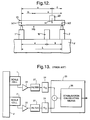
- the sensitivity adjusting means 52 for carrying out sensitivity adjusting processes on the filtered signals FW1, FW2 and FY includes sensitivity' calculating means 54 and sensitivity correcting means 56. Their operations will be explained in detail next with reference to Fig. 12, which is a schematic side view of the weighing machine of Figs. 10, 11A and 11B.
- M G indicates the weight and the position of the center of gravity of the weighing conveyor 10
- M1 and M2 are the loads on the scale cells 1 and 2
- L is the length of the weighing conveyor 10
- m and n are the distances of the center of gravity M G from the scale cells 1 and 2
- x and y are the distances of the target object 20 of weight M from the scale cells 1 and 2
- a and b are the distances of the floor vibration detecting cell 16 from the scale cells 1 and 2.
- the sensitivity correcting means 56 carries out sensitivity correction process on the filtered signals FW1, FW2 and FY. If the outputs from the scale cells due to the floor vibrations are Z1 and Z2, the floor vibration portion Z16 (outputted value of the filtered signal FY) at the output sensitivity of the floor vibration detecting cell 16 at its position obtained from Z1 and Z2 is:
- the weight M of the target object 20 can be obtained by a very simple formula, and this makes a high-speed weighing possible. Since only one floor vibration detecting cell 16 is employed, furthermore, the structure of the machine is simplified.
- the target object 20 is weighed while being transported on a weighing conveyor in all of the embodiments of the invention described above, this is not intended to limit the scope of the invention. This invention can be equally well applied to situations where the target object 20 is weighed in a stationary state.
- A/D converter need not be placed downstream of the multiplexer in any of the embodiments.
- the holders 11, 12, 13 and 14 for supporting the supporting plate 15 need not necessarily be structured as shown in Fig. 5.
Landscapes
- Physics & Mathematics (AREA)
- General Physics & Mathematics (AREA)
- Indication And Recording Devices For Special Purposes And Tariff Metering Devices (AREA)
- Measurement Of Mechanical Vibrations Or Ultrasonic Waves (AREA)
Applications Claiming Priority (7)
| Application Number | Priority Date | Filing Date | Title |
|---|---|---|---|
| JP33957893 | 1993-12-02 | ||
| JP339579/93 | 1993-12-02 | ||
| JP33957993 | 1993-12-02 | ||
| JP339578/93 | 1993-12-02 | ||
| JP293744/94 | 1994-11-01 | ||
| JP29374494A JP3539582B2 (ja) | 1993-12-02 | 1994-11-01 | 多点セル型計量装置 |
| JP239744/94 | 1994-11-01 |
Publications (2)
| Publication Number | Publication Date |
|---|---|
| EP0656530A1 true EP0656530A1 (de) | 1995-06-07 |
| EP0656530B1 EP0656530B1 (de) | 1998-01-28 |
Family
ID=27337844
Family Applications (1)
| Application Number | Title | Priority Date | Filing Date |
|---|---|---|---|
| EP94308839A Expired - Lifetime EP0656530B1 (de) | 1993-12-02 | 1994-11-30 | Plattformwaage |
Country Status (4)
| Country | Link |
|---|---|
| US (1) | US6013879A (de) |
| EP (1) | EP0656530B1 (de) |
| JP (1) | JP3539582B2 (de) |
| DE (1) | DE69408289T2 (de) |
Cited By (7)
| Publication number | Priority date | Publication date | Assignee | Title |
|---|---|---|---|---|
| FR2768222A1 (fr) * | 1997-09-05 | 1999-03-12 | Pellenc Sa | Dispositif et procede de pesage embarque et en continu de recolte, et machines de recolte en faisant application |
| EP0908706A1 (de) * | 1997-10-08 | 1999-04-14 | Ishida Co., Ltd. | Wägeeinrichtung zur Erzeugung einer automatischen Regelung eines Filters |
| WO2002037066A1 (en) * | 2000-11-06 | 2002-05-10 | David Lechtman | Method of operating a device exposed to ambient conditions and installation including such a device |
| EP1895280A2 (de) | 2006-09-04 | 2008-03-05 | Wipotec Wiege- und Positioniersysteme GmbH | Wägevorrichtung, insbesondere Wägezelle für eine Verbundwaage |
| EP2202498A3 (de) * | 2008-12-23 | 2011-09-14 | Wipotec Wiege- und Positioniersysteme GmbH | Einrichtung zur Erschütterungskompensation des Gewichtssignals eines Wägesensors |
| EP1715309B1 (de) * | 2005-04-19 | 2012-06-13 | Librawerk Maschinenfabrik GmbH | Behälterwaage |
| CN105251071A (zh) * | 2009-12-24 | 2016-01-20 | 昆山韦睿医疗科技有限公司 | 自动腹膜透析循环系统用称重单元 |
Families Citing this family (25)
| Publication number | Priority date | Publication date | Assignee | Title |
|---|---|---|---|---|
| US6313414B1 (en) * | 2000-01-31 | 2001-11-06 | Harvestmaster, Inc. | Slope and motion compensator for weighing on a dynamic platform |
| US6727438B1 (en) * | 2002-05-15 | 2004-04-27 | Steve Stokes | Method for determining oil and grease content using a reference weight signal for live cancellation of disturbances in the weighting signal |
| US6963036B1 (en) | 2002-11-01 | 2005-11-08 | Heinz Zicher | Accurate, high speed weighing apparatus and method |
| JP3808841B2 (ja) * | 2003-04-02 | 2006-08-16 | 株式会社イシダ | 重量検出装置 |
| US7297662B2 (en) * | 2004-01-29 | 2007-11-20 | Turbo-Chem International, Inc. | Method and composition for inhibiting lost circulation during well operation |
| DE102005018708B4 (de) * | 2005-04-21 | 2007-01-11 | Wipotec Wiege- Und Positioniersysteme Gmbh | Wägevorrichtung, insbesondere Mehrspur-Wägevorrichtung |
| JP4694292B2 (ja) * | 2005-07-13 | 2011-06-08 | 大和製衡株式会社 | 計量コンベヤ |
| JP2007101463A (ja) * | 2005-10-07 | 2007-04-19 | Ishida Co Ltd | 重量検出装置 |
| US7279645B1 (en) | 2006-05-12 | 2007-10-09 | Mettler-Toledo, Inc. | Multiple conveyor and scale weighing apparatus |
| EP2771746A1 (de) * | 2011-10-30 | 2014-09-03 | Paskal Technologies Agriculture Cooperative Societ Ltd. | Selbsterlernung einer pflanzenwachstumsstrategie in einem gewächshaus |
| EP2650660A1 (de) * | 2012-04-13 | 2013-10-16 | Mettler-Toledo Garvens GmbH | Metallmelderband mit integrierter Wägezelle |
| US20150157520A1 (en) * | 2013-12-05 | 2015-06-11 | Stryker Corporation | Patient support |
| US10935416B1 (en) | 2013-12-18 | 2021-03-02 | Amazon Technologies, Inc. | System for generating compensated weight data using a gyroscope |
| GB201405926D0 (en) * | 2014-04-02 | 2014-05-14 | Metryx Ltd | Semiconductor wafer weighing apparatus and methods |
| JP2016151461A (ja) * | 2015-02-17 | 2016-08-22 | 大和製衡株式会社 | 計量装置 |
| EP3187840A1 (de) * | 2015-12-31 | 2017-07-05 | Radwag Wagi Elektroniczne Witold Lewandowski | Verfahren zur kompensation von schwingungsauswirkungen, die auf die massenmessung ausgeübt werden, mit verwendung einer dynamischen waage, mit anwendung eines empirischen mathematischen modells |
| JP6447530B2 (ja) * | 2016-01-29 | 2019-01-09 | オムロン株式会社 | 信号処理装置、信号処理装置の制御方法、制御プログラム、および記録媒体 |
| CN106742118A (zh) * | 2016-11-19 | 2017-05-31 | 无锡当升智能装备科技有限公司 | 包装机的称重台 |
| CN106428674A (zh) * | 2016-11-19 | 2017-02-22 | 无锡当升智能装备科技有限公司 | 包装机的称重装置 |
| JP6987451B2 (ja) * | 2017-12-20 | 2022-01-05 | 大和製衡株式会社 | 重量選別機 |
| US11642028B2 (en) * | 2019-06-05 | 2023-05-09 | Aegle BioTech, LLC | Force reading devices and methods |
| JP7462295B2 (ja) * | 2020-03-19 | 2024-04-05 | 株式会社イシダ | 計量装置 |
| ES2926502T3 (es) * | 2020-06-19 | 2022-10-26 | Multipond Waegetechnik Gmbh | Procedimiento de procesamiento de señales para balanzas de cabezales múltiples |
| CN113350075A (zh) * | 2021-06-24 | 2021-09-07 | 姜翠华 | 一种协助重症患者翻身侧身的病床 |
| JP2024038644A (ja) * | 2022-09-08 | 2024-03-21 | 大和製衡株式会社 | 金属検出機付き重量選別装置 |
Citations (6)
| Publication number | Priority date | Publication date | Assignee | Title |
|---|---|---|---|---|
| EP0122796A1 (de) * | 1983-04-14 | 1984-10-24 | Kabushiki Kaisha Ishida Koki Seisakusho | Waage |
| US4751973A (en) * | 1987-09-16 | 1988-06-21 | Pitney Bowes Inc. | Load cell scale with reference channel for live load correction |
| EP0403200A1 (de) * | 1989-06-12 | 1990-12-19 | Ncr International Inc. | Verfahren für Waagenkalibrierung und für Wägung |
| EP0430695A2 (de) * | 1989-12-01 | 1991-06-05 | ISHIDA CO., Ltd. | Waage |
| EP0429725A1 (de) * | 1989-11-29 | 1991-06-05 | Yamato Scale Company, Limited | Einrichtung und Verfahren zur Filterung von gewichtsanzeigenden Signalen einer Waage |
| EP0622617A1 (de) * | 1993-04-30 | 1994-11-02 | ISHIDA CO., Ltd. | Wägeapparat |
Family Cites Families (10)
| Publication number | Priority date | Publication date | Assignee | Title |
|---|---|---|---|---|
| CH621409A5 (de) * | 1978-02-24 | 1981-01-30 | Mettler Instrumente Ag | |
| US4593778A (en) * | 1983-06-21 | 1986-06-10 | Kabushiki Kaisha Ishida Koki Seisakusho | Weighing machine with dummy load cell for error correction |
| AU565314B2 (en) * | 1983-12-28 | 1987-09-10 | K.S. Ishida K.K. | Weight sensor |
| US4660662A (en) * | 1985-09-11 | 1987-04-28 | National Controls, Inc. | Digital electronic scale with stabilized display |
| US4804052A (en) * | 1987-11-30 | 1989-02-14 | Toledo Scale Corporation | Compensated multiple load cell scale |
| US5172783A (en) * | 1991-07-01 | 1992-12-22 | Pitney Bowes, Inc. | Weighing scale with validating reference channel |
| US5296655A (en) * | 1992-02-10 | 1994-03-22 | Beowulf Corporation | Control system for multiple input scales |
| US5220969A (en) * | 1992-07-31 | 1993-06-22 | Pitney Bowes Inc. | Scale having variable thickness document feed belt |
| US5561274A (en) * | 1992-09-15 | 1996-10-01 | Intel Corporation | Apparatus for weighing objects |
| EP0756158B1 (de) * | 1995-07-26 | 2002-10-02 | ISHIDA CO., Ltd. | Wägeeinrichtung |
-
1994
- 1994-11-01 JP JP29374494A patent/JP3539582B2/ja not_active Expired - Fee Related
- 1994-11-30 DE DE69408289T patent/DE69408289T2/de not_active Expired - Fee Related
- 1994-11-30 EP EP94308839A patent/EP0656530B1/de not_active Expired - Lifetime
-
1997
- 1997-09-03 US US08/923,060 patent/US6013879A/en not_active Expired - Lifetime
Patent Citations (6)
| Publication number | Priority date | Publication date | Assignee | Title |
|---|---|---|---|---|
| EP0122796A1 (de) * | 1983-04-14 | 1984-10-24 | Kabushiki Kaisha Ishida Koki Seisakusho | Waage |
| US4751973A (en) * | 1987-09-16 | 1988-06-21 | Pitney Bowes Inc. | Load cell scale with reference channel for live load correction |
| EP0403200A1 (de) * | 1989-06-12 | 1990-12-19 | Ncr International Inc. | Verfahren für Waagenkalibrierung und für Wägung |
| EP0429725A1 (de) * | 1989-11-29 | 1991-06-05 | Yamato Scale Company, Limited | Einrichtung und Verfahren zur Filterung von gewichtsanzeigenden Signalen einer Waage |
| EP0430695A2 (de) * | 1989-12-01 | 1991-06-05 | ISHIDA CO., Ltd. | Waage |
| EP0622617A1 (de) * | 1993-04-30 | 1994-11-02 | ISHIDA CO., Ltd. | Wägeapparat |
Cited By (12)
| Publication number | Priority date | Publication date | Assignee | Title |
|---|---|---|---|---|
| FR2768222A1 (fr) * | 1997-09-05 | 1999-03-12 | Pellenc Sa | Dispositif et procede de pesage embarque et en continu de recolte, et machines de recolte en faisant application |
| WO1999013301A1 (fr) * | 1997-09-05 | 1999-03-18 | Pellenc Societe Anonyme | Dispositif et procede de pesage embarque et en continu de recolte, et machines de recolte en faisant application |
| US6283853B1 (en) | 1997-09-05 | 2001-09-04 | Pellenc S.A. | On-board device and method for continuous weighing of harvest and harvesting machines using same |
| EP0908706A1 (de) * | 1997-10-08 | 1999-04-14 | Ishida Co., Ltd. | Wägeeinrichtung zur Erzeugung einer automatischen Regelung eines Filters |
| WO2002037066A1 (en) * | 2000-11-06 | 2002-05-10 | David Lechtman | Method of operating a device exposed to ambient conditions and installation including such a device |
| EP1715309B1 (de) * | 2005-04-19 | 2012-06-13 | Librawerk Maschinenfabrik GmbH | Behälterwaage |
| EP1895280A2 (de) | 2006-09-04 | 2008-03-05 | Wipotec Wiege- und Positioniersysteme GmbH | Wägevorrichtung, insbesondere Wägezelle für eine Verbundwaage |
| DE102006041836B4 (de) * | 2006-09-04 | 2009-04-02 | Wipotec Wiege- Und Positioniersysteme Gmbh | Wägevorrichtung, insbesondere Wägezelle für eine Verbundwaage |
| EP2202498A3 (de) * | 2008-12-23 | 2011-09-14 | Wipotec Wiege- und Positioniersysteme GmbH | Einrichtung zur Erschütterungskompensation des Gewichtssignals eines Wägesensors |
| US9417118B2 (en) | 2008-12-23 | 2016-08-16 | Wipotec Wiege- Und Positioniersysteme Gmbh | Device for vibration compensation of the weight signal of a weighing sensor |
| CN105251071A (zh) * | 2009-12-24 | 2016-01-20 | 昆山韦睿医疗科技有限公司 | 自动腹膜透析循环系统用称重单元 |
| CN105251071B (zh) * | 2009-12-24 | 2017-08-25 | 昆山韦睿医疗科技有限公司 | 自动腹膜透析循环系统用称重单元 |
Also Published As
| Publication number | Publication date |
|---|---|
| JPH07209066A (ja) | 1995-08-11 |
| DE69408289T2 (de) | 1998-06-10 |
| JP3539582B2 (ja) | 2004-07-07 |
| DE69408289D1 (de) | 1998-03-05 |
| EP0656530B1 (de) | 1998-01-28 |
| US6013879A (en) | 2000-01-11 |
Similar Documents
| Publication | Publication Date | Title |
|---|---|---|
| EP0656530A1 (de) | Wägeapparat mit Vielfachpunktmesszelle | |
| US5942695A (en) | Method and apparatus for measuring seat loading by strain gauge | |
| EP0430695B1 (de) | Waage | |
| EP0534736B1 (de) | Waage zur Schnellbestimmung von Gewichten | |
| EP0534738B1 (de) | Verfahren und Gerät zur schnellen Bestimmung von Gewichten | |
| US5936206A (en) | Weighing machines with means for correcting effects of floor vibrations on weight signals therefrom | |
| EP0711983B1 (de) | An einem Förderer befestigte Wägeeinrichtung | |
| CN100595530C (zh) | 称重装置,特别是多轨迹称重装置 | |
| JP2002267524A (ja) | シート重量計測装置 | |
| JP3384753B2 (ja) | シート荷重計測装置 | |
| EP0818669B1 (de) | Waage mit Sperrung der Vibrationskorrektur | |
| JP3642639B2 (ja) | 複数の荷重変換手段を備える計量装置 | |
| US6963036B1 (en) | Accurate, high speed weighing apparatus and method | |
| JP3251706B2 (ja) | 計量装置 | |
| EP0671609B1 (de) | Schwingungsaufnehmer und Wägegerät | |
| JPH0786071B2 (ja) | エレベータのかご負荷検出器取付構造 | |
| JP3251707B2 (ja) | 組合せ計量装置 | |
| JP3693764B2 (ja) | 計量方法及び計量装置 | |
| JP3251754B2 (ja) | 床振動補正付き計量装置 | |
| JP3397418B2 (ja) | ロードセル | |
| JP3631546B2 (ja) | 計量装置 | |
| JPH0829239A (ja) | コンベア秤量機 | |
| JP3600355B2 (ja) | 秤 | |
| JPH11193001A (ja) | 物品の振動式搬送装置 | |
| JP3525364B2 (ja) | 計量方法および装置 |
Legal Events
| Date | Code | Title | Description |
|---|---|---|---|
| PUAI | Public reference made under article 153(3) epc to a published international application that has entered the european phase |
Free format text: ORIGINAL CODE: 0009012 |
|
| AK | Designated contracting states |
Kind code of ref document: A1 Designated state(s): DE FR GB IT |
|
| 17P | Request for examination filed |
Effective date: 19951124 |
|
| GRAG | Despatch of communication of intention to grant |
Free format text: ORIGINAL CODE: EPIDOS AGRA |
|
| 17Q | First examination report despatched |
Effective date: 19970422 |
|
| GRAG | Despatch of communication of intention to grant |
Free format text: ORIGINAL CODE: EPIDOS AGRA |
|
| GRAH | Despatch of communication of intention to grant a patent |
Free format text: ORIGINAL CODE: EPIDOS IGRA |
|
| GRAH | Despatch of communication of intention to grant a patent |
Free format text: ORIGINAL CODE: EPIDOS IGRA |
|
| GRAA | (expected) grant |
Free format text: ORIGINAL CODE: 0009210 |
|
| AK | Designated contracting states |
Kind code of ref document: B1 Designated state(s): DE FR GB IT |
|
| ET | Fr: translation filed | ||
| REF | Corresponds to: |
Ref document number: 69408289 Country of ref document: DE Date of ref document: 19980305 |
|
| ITF | It: translation for a ep patent filed | ||
| PLBQ | Unpublished change to opponent data |
Free format text: ORIGINAL CODE: EPIDOS OPPO |
|
| PLBI | Opposition filed |
Free format text: ORIGINAL CODE: 0009260 |
|
| 26 | Opposition filed |
Opponent name: SCHENCK PROCESS GMBH Effective date: 19981028 |
|
| PLBF | Reply of patent proprietor to notice(s) of opposition |
Free format text: ORIGINAL CODE: EPIDOS OBSO |
|
| PLBF | Reply of patent proprietor to notice(s) of opposition |
Free format text: ORIGINAL CODE: EPIDOS OBSO |
|
| PLBF | Reply of patent proprietor to notice(s) of opposition |
Free format text: ORIGINAL CODE: EPIDOS OBSO |
|
| PLBF | Reply of patent proprietor to notice(s) of opposition |
Free format text: ORIGINAL CODE: EPIDOS OBSO |
|
| REG | Reference to a national code |
Ref country code: GB Ref legal event code: IF02 |
|
| PGFP | Annual fee paid to national office [announced via postgrant information from national office to epo] |
Ref country code: FR Payment date: 20031110 Year of fee payment: 10 |
|
| PGFP | Annual fee paid to national office [announced via postgrant information from national office to epo] |
Ref country code: GB Payment date: 20031126 Year of fee payment: 10 |
|
| PGFP | Annual fee paid to national office [announced via postgrant information from national office to epo] |
Ref country code: DE Payment date: 20031211 Year of fee payment: 10 |
|
| PG25 | Lapsed in a contracting state [announced via postgrant information from national office to epo] |
Ref country code: GB Free format text: LAPSE BECAUSE OF NON-PAYMENT OF DUE FEES Effective date: 20041130 |
|
| PLCK | Communication despatched that opposition was rejected |
Free format text: ORIGINAL CODE: EPIDOSNREJ1 |
|
| PG25 | Lapsed in a contracting state [announced via postgrant information from national office to epo] |
Ref country code: DE Free format text: LAPSE BECAUSE OF NON-PAYMENT OF DUE FEES Effective date: 20050601 |
|
| PLBN | Opposition rejected |
Free format text: ORIGINAL CODE: 0009273 |
|
| STAA | Information on the status of an ep patent application or granted ep patent |
Free format text: STATUS: OPPOSITION REJECTED |
|
| GBPC | Gb: european patent ceased through non-payment of renewal fee |
Effective date: 20041130 |
|
| PG25 | Lapsed in a contracting state [announced via postgrant information from national office to epo] |
Ref country code: FR Free format text: LAPSE BECAUSE OF NON-PAYMENT OF DUE FEES Effective date: 20050729 |
|
| 27O | Opposition rejected |
Effective date: 20050414 |
|
| REG | Reference to a national code |
Ref country code: FR Ref legal event code: ST |
|
| PG25 | Lapsed in a contracting state [announced via postgrant information from national office to epo] |
Ref country code: IT Free format text: LAPSE BECAUSE OF NON-PAYMENT OF DUE FEES Effective date: 20051130 |