EP0656729A2 - Méthode et appareil pour éditer ou mixer des images comprimées - Google Patents
Méthode et appareil pour éditer ou mixer des images comprimées Download PDFInfo
- Publication number
- EP0656729A2 EP0656729A2 EP94308669A EP94308669A EP0656729A2 EP 0656729 A2 EP0656729 A2 EP 0656729A2 EP 94308669 A EP94308669 A EP 94308669A EP 94308669 A EP94308669 A EP 94308669A EP 0656729 A2 EP0656729 A2 EP 0656729A2
- Authority
- EP
- European Patent Office
- Prior art keywords
- picture data
- frame
- prediction
- compressed
- coding
- Prior art date
- Legal status (The legal status is an assumption and is not a legal conclusion. Google has not performed a legal analysis and makes no representation as to the accuracy of the status listed.)
- Granted
Links
Images


Classifications
-
- H—ELECTRICITY
- H04—ELECTRIC COMMUNICATION TECHNIQUE
- H04N—PICTORIAL COMMUNICATION, e.g. TELEVISION
- H04N21/00—Selective content distribution, e.g. interactive television or video on demand [VOD]
- H04N21/20—Servers specifically adapted for the distribution of content, e.g. VOD servers; Operations thereof
- H04N21/23—Processing of content or additional data; Elementary server operations; Server middleware
- H04N21/234—Processing of video elementary streams, e.g. splicing of video streams or manipulating encoded video stream scene graphs
- H04N21/23424—Processing of video elementary streams, e.g. splicing of video streams or manipulating encoded video stream scene graphs involving splicing one content stream with another content stream, e.g. for inserting or substituting an advertisement
-
- G—PHYSICS
- G11—INFORMATION STORAGE
- G11B—INFORMATION STORAGE BASED ON RELATIVE MOVEMENT BETWEEN RECORD CARRIER AND TRANSDUCER
- G11B27/00—Editing; Indexing; Addressing; Timing or synchronising; Monitoring; Measuring tape travel
- G11B27/02—Editing, e.g. varying the order of information signals recorded on, or reproduced from, record carriers
- G11B27/031—Electronic editing of digitised analogue information signals, e.g. audio or video signals
- G11B27/036—Insert-editing
-
- H—ELECTRICITY
- H04—ELECTRIC COMMUNICATION TECHNIQUE
- H04N—PICTORIAL COMMUNICATION, e.g. TELEVISION
- H04N19/00—Methods or arrangements for coding, decoding, compressing or decompressing digital video signals
- H04N19/40—Methods or arrangements for coding, decoding, compressing or decompressing digital video signals using video transcoding, i.e. partial or full decoding of a coded input stream followed by re-encoding of the decoded output stream
-
- H—ELECTRICITY
- H04—ELECTRIC COMMUNICATION TECHNIQUE
- H04N—PICTORIAL COMMUNICATION, e.g. TELEVISION
- H04N19/00—Methods or arrangements for coding, decoding, compressing or decompressing digital video signals
- H04N19/46—Embedding additional information in the video signal during the compression process
- H04N19/467—Embedding additional information in the video signal during the compression process characterised by the embedded information being invisible, e.g. watermarking
-
- H—ELECTRICITY
- H04—ELECTRIC COMMUNICATION TECHNIQUE
- H04N—PICTORIAL COMMUNICATION, e.g. TELEVISION
- H04N19/00—Methods or arrangements for coding, decoding, compressing or decompressing digital video signals
- H04N19/48—Methods or arrangements for coding, decoding, compressing or decompressing digital video signals using compressed domain processing techniques other than decoding, e.g. modification of transform coefficients, variable length coding [VLC] data or run-length data
-
- H—ELECTRICITY
- H04—ELECTRIC COMMUNICATION TECHNIQUE
- H04N—PICTORIAL COMMUNICATION, e.g. TELEVISION
- H04N19/00—Methods or arrangements for coding, decoding, compressing or decompressing digital video signals
- H04N19/50—Methods or arrangements for coding, decoding, compressing or decompressing digital video signals using predictive coding
- H04N19/503—Methods or arrangements for coding, decoding, compressing or decompressing digital video signals using predictive coding involving temporal prediction
- H04N19/51—Motion estimation or motion compensation
- H04N19/577—Motion compensation with bidirectional frame interpolation, i.e. using B-pictures
-
- H—ELECTRICITY
- H04—ELECTRIC COMMUNICATION TECHNIQUE
- H04N—PICTORIAL COMMUNICATION, e.g. TELEVISION
- H04N19/00—Methods or arrangements for coding, decoding, compressing or decompressing digital video signals
- H04N19/60—Methods or arrangements for coding, decoding, compressing or decompressing digital video signals using transform coding
- H04N19/61—Methods or arrangements for coding, decoding, compressing or decompressing digital video signals using transform coding in combination with predictive coding
-
- H—ELECTRICITY
- H04—ELECTRIC COMMUNICATION TECHNIQUE
- H04N—PICTORIAL COMMUNICATION, e.g. TELEVISION
- H04N19/00—Methods or arrangements for coding, decoding, compressing or decompressing digital video signals
- H04N19/90—Methods or arrangements for coding, decoding, compressing or decompressing digital video signals using coding techniques not provided for in groups H04N19/10-H04N19/85, e.g. fractals
-
- H—ELECTRICITY
- H04—ELECTRIC COMMUNICATION TECHNIQUE
- H04N—PICTORIAL COMMUNICATION, e.g. TELEVISION
- H04N21/00—Selective content distribution, e.g. interactive television or video on demand [VOD]
- H04N21/20—Servers specifically adapted for the distribution of content, e.g. VOD servers; Operations thereof
- H04N21/23—Processing of content or additional data; Elementary server operations; Server middleware
- H04N21/234—Processing of video elementary streams, e.g. splicing of video streams or manipulating encoded video stream scene graphs
- H04N21/2343—Processing of video elementary streams, e.g. splicing of video streams or manipulating encoded video stream scene graphs involving reformatting operations of video signals for distribution or compliance with end-user requests or end-user device requirements
-
- H—ELECTRICITY
- H04—ELECTRIC COMMUNICATION TECHNIQUE
- H04N—PICTORIAL COMMUNICATION, e.g. TELEVISION
- H04N21/00—Selective content distribution, e.g. interactive television or video on demand [VOD]
- H04N21/20—Servers specifically adapted for the distribution of content, e.g. VOD servers; Operations thereof
- H04N21/23—Processing of content or additional data; Elementary server operations; Server middleware
- H04N21/236—Assembling of a multiplex stream, e.g. transport stream, by combining a video stream with other content or additional data, e.g. inserting a URL [Uniform Resource Locator] into a video stream, multiplexing software data into a video stream; Remultiplexing of multiplex streams; Insertion of stuffing bits into the multiplex stream, e.g. to obtain a constant bit-rate; Assembling of a packetised elementary stream
-
- H—ELECTRICITY
- H04—ELECTRIC COMMUNICATION TECHNIQUE
- H04N—PICTORIAL COMMUNICATION, e.g. TELEVISION
- H04N5/00—Details of television systems
- H04N5/222—Studio circuitry; Studio devices; Studio equipment
- H04N5/262—Studio circuits, e.g. for mixing, switching-over, change of character of image, other special effects ; Cameras specially adapted for the electronic generation of special effects
- H04N5/265—Mixing
Definitions
- the present invention relates to a compressed picture editing method for editing compressed picture data, and a picture coding apparatus for mixing a part or whole of compressed picture data with other compressed picture data or real time picture data.
- a digital video signal possesses an enormous amount of information, and picture coding is indispensable for transmission and recording.
- picture coding techniques have been developed recently, and some of them are produced as encoders and decoders.
- Fig. 15 is a block diagram of the conventional picture coding apparatus.
- the apparatus comprises a motion detector 81, a DCT (discrete cosine transform) mode judging circuit 82, a DCT circuit 83, a quantizing circuit 84, a variable length coding circuit 85, an inverse quantizing circuit 86, an inverse DCT circuit 87, a frame memory 88, and a motion compensation circuit 89.
- Fig. 16 is an explanatory diagram of motion compensation predicting method
- Fig. 17 is an explanatory diagram of the frame memory 88 and the motion compensation circuit 89.
- a video signal is scanned by interlacing, and is entered as being divided into frame units.
- a picture in a first frame to be coded that is, frame t in Fig. 16 is processed by intraframe coding using the data within the frame.
- the DCT mode judging circuit 82 detects the motion of the input picture data in each two-dimensional block of pixels by, for example, calculating inter-line differences, determines from the detection result whether to perform DCT in frame unit or in field unit, and outputs the determination result as DCT mode information.
- the DCT circuit 83 receives the DCT mode information, and performs the DCT in either frame unit or field unit to transform the picture data into transform coefficients.
- the transform coefficients are quantized in the quantizing circuit 84, and variable-length coded in the variable length coding circuit 85 to obtain a coded bit stream which is sent out to a transmission line.
- the quantized transform coefficients are simultaneously fed into the inverse quantizing circuit 86 and the inverse DCT circuit 87 to be returned to real time data, and stored in the frame memory 88.
- the calculating method of the predicted picture value includes forward prediction, backward prediction, and bidirectional prediction.
- Fig. 16 is an explanatory diagram of the prediction methods.
- the frame at time t is intraframe coded (hereinafter, an intraframe coded frame is called I frame).
- I frame intraframe coded
- a difference of the frame at time t+3 from a frame obtained by decoding the I frame is calculated after motion compensation, and this difference is coded.
- This operation for predicting a frame which is ahead in time is called forward prediction (hereinafter, a frame coded by forward prediction is called P frame).
- Frames at time t+1, t+2 are similarly subjected to motion compensation, difference calculation and difference coding by using frames decoded from the I and P frames.
- the predicted picture is composed by selecting in a block having a minimum error from the blocks of I frame (forward prediction), P frame (backward prediction), and the mean of I frame and P frame (bidirectional prediction) (hereinafter, a frame coded at a part or whole thereof by bidirectional prediction is called B frame).
- the B frame is predicted from frames before and after in time, so that a newly appearing object can be predicted accurately, thereby enhancing the coding efficiency.
- the motion vector to be used in prediction is detected in the motion detector 81 on a two-dimensional block by block basis by, for example, the well-known full search method.
- the frame memory 88 and the motion compensation circuit 89 generate a next predicted value compensated for the motion in each two-dimensional block.
- Fig. 17 is an example of constitution of the motion compensation circuit 89.
- generation of predicted value of bidirectional prediction The motion vector calculated in the motion detector 81 is fed into an address circuit 882 in the frame memory 88, and pictures of I and P frames stored in the frame memory 881 are read out.
- the two-dimensional blocks are formed in each frame or each field, and the vectors and predicted picture values are generated respectively.
- prediction errors forward prediction error, bidirectional prediction error and backward prediction error by using frame vectors
- forward prediction error, bidirectional prediction error and backward prediction error by using field vectors that is, six kinds of errors in total are calculated in square error calculating circuits 893 to 898.
- a smallest one of the six errors is selected in an error comparator 899, and the predicted values and prediction mode information are issued.
- the above prediction mode information, motion vector, and DCT mode information are variable-length coded in the variable length coding circuit 85, and sent out to the transmission line together with the DCT transform coefficients.
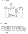
- FIG. 18 is an explanatory diagram showing a conventional editing method of compressed picture data. Referring now to Fig. 18, the problems are explained below.
- Fig. 18 suppose to link compressed picture data of (a) and (b) at the dotted line portions.
- Numerals given in Fig. 18 represent frame numbers. Since the B frame is coded after the I and P frames have been coded, the sequence of the coded frames is changed from the sequence to be displayed.
- the P and B frames right after the editing point that is, the P frame of frame number 8 and the B frames of frame numbers 6 and 7 in the compressed picture data (b) cannot be decoded because the I frame of frame number 5 used in prediction is lost. Also, the pictures after frame 9 used in prediction of the P frame of frame number 11 cannot be decoded.
- the invention presents a compressed picture editing method comprising the steps of: receiving first and second compressed picture data each having been obtained by prediction-coding by at least one type of prediction out of a forward prediction for predicting a picture data in a current frame from a previous frame ahead in time, a backward prediction for predicting from a subsequent frame behind in time, and a bidirectional prediction simultaneously using both the forward prediction and the backward prediction; decoding the second compressed picture data; intraframe coding a frame of the decoded picture corresponding to a editing point; prediction-coding again a part or whole of the other frames of the decoded picture by using motion compensation, motion vector, and orthogonal transform mode information obtained by decoding the second compressed picture data to obtain modified second compressed picture data; and linking the first compressed picture data with the modified second compressed picture data.
- the compressed picture data is once decoded, and the frame right after the editing point is coded again into an I frame, so that the predicted picture will not be lost by editing.
- the motion compensation, motion vector and DCT mode information obtained by decoding are used, so that a motion detector and a DCT mode judging circuit required for mass calculation in the conventional picture encoder are not necessary, and the motion compensation circuit is simplified. Accordingly, the compressed picture data can be edited in a simple constitution.
- a first compressed picture data is decoded, the decoded picture data and a second picture data are added to create a mixed picture data, and the mixed picture data is prediction-coded again by using motion compensation information, motion vector, and orthogonal transform mode information obtained by decoding the first compressed picture data.
- a first compressed picture data and a second compressed picture data having been compression-coded in the same manner as in the first compressed picture data are decoded, orthogonal transform coefficients of the first compressed picture data and the second compressed picture data are added to create a mixed picture data, and the mixed picture data is prediction-coded again by using motion compensation information, motion vector, and orthogonal transform mode information obtained by decoding the first compressed picture data.
- the compressed picture data can be mixed in a simple constitution.
- the picture data to be mixed may be multiplexed on the compressed picture data in transmission, so that a picture mixing apparatus light in the load at the coding side can be realized.
- Fig. 1 is a block diagram of a compressed picture encoder in a first embodiment of the invention.
- Fig. 2 is a constitution diagram of a simplified motion compensation circuit and a frame memory in the first embodiment of the invention.
- Fig. 3 is an explanatory diagram of algorithm showing an example of operation of CPU in the first embodiment of the invention.
- Fig. 4 is an explanatory diagram showing an editing method of compressed picture data in the first embodiment of the invention.
- Fig. 5 is an explanatory diagram showing an editing method of compressed picture data in a second embodiment of the invention.
- Fig. 6 is an explanatory diagram showing an editing method of compressed picture data in a third embodiment of the invention.
- Fig. 7 is an explanatory diagram showing an editing method of compressed picture data in the third embodiment of the invention.
- Fig. 8 is a block diagram of a picture mixing apparatus in a fourth embodiment of the invention.
- Fig. 9 is an explanatory diagram of algorithm showing an example of operation of CPU in the fourth embodiment of the invention.
- Fig. 10 is an explanatory diagram showing a motion compensation method of mixed picture in the fourth embodiment of the invention.
- Fig. 11 is a block diagram of a picture mixing apparatus in a fifth embodiment of the invention.
- Fig. 12 is an explanatory diagram of a compressed picture mixing method in a sixth embodiment of the invention.
- Fig. 13 is an explanatory diagram of a compressed picture mixing apparatus in the sixth embodiment of the invention.
- Fig. 14 is a block diagram of the picture mixing apparatus in the sixth embodiment of the invention.
- Fig. 15 is a block diagram of a conventional picture encoder.
- Fig. 16 is an explanatory diagram of a conventional motion compensation prediction method.
- Fig. 17 is a constitution diagram of conventional motion compensation circuit and frame memory.
- Fig. 18 is an explanatory diagram showing a conventional editing method of compressed picture data.
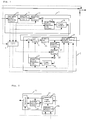
- Fig. 1 is a block diagram of a picture encoder in the first embodiment of the invention.
- reference numeral 1 denotes a picture decoding unit which comprises a variable length decoding circuit 11, an inverse quantizing circuit 12, an inverse DCT circuit 13, a frame memory 14, and a simplified motion compensation circuit 15.
- Reference numeral 2 is a picture encoding unit which comprises a DCT circuit 21, a quantizing circuit 22, a variable length coding circuit 23, an inverse quantizing circuit 24, an inverse DCT circuit 25, a frame memory 26, and a simplified motion compensation circuit 27.
- Reference numeral 3 is a control unit which comprises a CPU.
- Fig. 2 is a detailed structural diagram of the simplified motion compensation circuit 15 and frame memory 14, Fig.
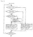
- FIG. 3 is an explanatory diagram of algorithm showing an example of operation of the CPU 3
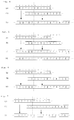
- Fig. 4 is an explanatory diagram showing an editing method of compressed picture data.
- the frame accompanied by an apostrophe (') denotes a re-coded frame. It is the same in Figs. 5 through 7.
- the editing point is supposed to be a P frame.
- the compressed picture data (a) in Fig. 4 enters the picture encoder in Fig. 1, it is put out as it is until coming to the editing point indicated by the dotted line in Fig. 4.
- the compressed picture data (b) in Fig. 4 is put in the picture decoding unit 1, but the output of the picture coding unit 2 is not sent outside up to the editing point.
- the compressed picture data (b) is decoded in the picture decoding unit 1.
- inverse DCT is performed on a frame by frame or field by field basis to return to real time picture data.
- a predicted picture is generated in the frame memory 14 and simplified motion compensation circuit 15, and is summed with the inverse DCT circuit output data, thereby creating decoded picture data.
- Fig. 2 is a constitutional example of the frame memory 14 and simplified motion compensation circuit 15. As compared with the conventional picture encoder, the constitution of the frame memory 14 is the same, but the motion compensation circuit 15 is substantially different.
- any square error calculation circuit is not needed in the picture decoding unit, and hence it only requires, as shown in Fig. 2, a mean calculating circuit 151 necessary when the bidirectional prediction is selected, and a selector 152 for issuing a predicted picture depending on the motion compensation mode information.
- the P frame right after the editing point, among the compressed picture data (b), is re-coded as an I frame, and is linked to the compressed picture data (a) and issued.
- the compressed picture data (b) the B frames of frame numbers 6, 7 are coded again by backward prediction because the I frame of frame number 5 necessary for forward prediction has been lost by editing.
- the predicted picture is set again to a correct one, and the P frame is coded again into a new P frame, and the B frame B into a new B frame.
- the re-coding method is nearly the same as in the prior art, except that the motion compensation mode information, motion vector, and DCT changeover information are obtained by decoding the compressed picture data (b). Therefore, the picture coding unit 2 does not require a motion detection circuit and a DCT mode judging circuit for mass calculation as used in the conventional picture encoder in Fig. 14, and the motion compensation circuit 89 can be replaced by the simplified motion compensation circuit 27 same as the one in the decoding apparatus. All of the control is effected by the CPU 3, and its algorithm is shown in Fig. 3.
- Fig. 3 shows a flow chart of the main routine showing the entire operation, sub-routine for coding the P frame right after the editing point used in the main routine into an I frame, sub-routine for coding the B frame into a P frame by using backward prediction only, sub-routine for re-coding the P frame and B frame, and intraframe coded block coding sub-routine and backward prediction block coding sub-routine for coding by changing the motion compensation mode of block of each frame being used in the foregoing sub-routines.
- a reception buffer of a specific capacity is provided, and deviation of transmission rate and decoding speed of the decoder is absorbed.
- compression and coding are effected while controlling so that the reception buffer of the decoder may cause neither overflow nor underflow. Similar operation is needed when editing compressed picture data.
- the CPU 3 sequentially calculates the buffer content in the reception buffer, and the quantizing width of the quantizing circuit 22 is controlled if necessary so that the compressed picture data after editing may cause neither overflow nor underflow of the reception buffer.
- the compressed image data to be edited is re-coded in the picture encoder of a simple constitution, even the compressed picture data using interframe difference coding can be edited without losing the compressed picture data after splicing.
- Fig. 5 is an explanatory diagram of an editing method of picture compressed data in a second embodiment of the invention.
- the picture compressed data of (b) in Fig. 5 contains an I frame after the editing point. From the editing point to the point before the frame number 11, the frames are re-coded in the same manner as in the first embodiment. Since the I frame of frame number 11 has been coded within the frame, it is not affected by editing. Therefore, the I frame is not re-coded. As for the B frames of frame numbers 9, 10, since the P frame of frame number 8 is coded newly into an I frame, the B frames 9, 10 are re-coded by using the newly coded I frame.
- the number of frames to be re-coded may be decreased, and picture quality deterioration due to re-coding may be kept to a minimum limit.
- frames after frame number 14 are not re-coded because the I frame of frame number 11 is not re-coded.
- the B frame right after the I frame but also all P and B frames may be re-coded as shown in (d) of Fig. 5.
- Fig. 6 and Fig. 7 are explanatory diagrams of editing method of picture compressed data in a third embodiment of the invention.
- the editing point in (b) of Fig. 6 of the compressed picture data to be connected is in a B frame.
- the editing point and the B frame continuous to the editing point cannot be decoded because the I or P frame used in prediction is lost at the time of coding in the first and second embodiments.
- an I or P frame just before the editing point used in prediction is inserted by the number of undecodable B frames.
- the frame just before the editing point used in prediction is an I frame, as shown in (c) of Fig.
- a P frame it is re-coded into an I frame as shown in (c) of Fig. 7. If the reception buffer is a problem, same as in the second embodiment, even in the case of the I frame, it is possible to re-code to control the quantizing width so as not to cause overflow or underflow.
- the picture quality deterioration due to re-coding may be kept to a minimum, while editing is enabled.
- intraframe coding block in motion compensation mode of each block is omitted in explanation, but generally intraframe coding block mode can be selected on a two-dimensional block by block basis in the frame.
- the motion compensation mode of forward prediction block or the like can be re-coded in the same motion compensation mode as the motion vector is not contained in the compressed picture data. In such a case, it can be re-coded by selecting an intraframe coding block.
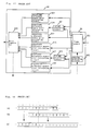
- Fig. 8 is a block diagram of a picture mixing apparatus in the fourth embodiment of the invention.
- reference numeral 1 denotes a picture decoding unit
- 2 is a picture coding unit, and they operate in the same way as in the first embodiment.
- Fig.9 is an explanatory diagram of algorithm showing an example of operation of CPU 3
- Fig. 10 is an explanatory diagram showing the motion compensation method of mixed picture.
- a picture data with a compressed picture data that has been prediction-coded.
- the compressed picture data in Fig. 8 is entered from an input terminal 16, while a certain picture data is fed from an input terminal 41.
- the compressed picture data is decoded in the picture decoding unit 1 in the same way as in the first embodiment.
- the picture data to be mixed may be either an uncompressed picture data or another compressed picture data.
- the picture information detector 4 is a circuit for detecting the picture information to be used in coding a mixed picture. It may be omitted if it is not necessary to enhance the coding efficiency.
- the picture information to be detected may include, in the case of uncompressed picture data, motion information showing how may pixels in the picture are moving between frames.
- the picture information detector may be composed in the same way as the picture decoding circuit 1, and the information to be detected may include motion vector, motion compensation information, and orthogonal transform mode information.
- Mixing is achieved by adding the picture data decoded by the picture decoding unit 1 and the picture data output-ted from the picture information detector 4.
- mixing can be started from any frame, but it is desired to start from an intraframe coded frame (I frame).
- I frame intraframe coded frame
- the content is not changed frequently such as the superimposed dialogue. In such a case, by changing the content at intervals of the intraframe coding frames, the interframe difference can be decreased, so that the coding efficiency can be enhanced.
- Fig. 10 shows the motion compensation method of blocks in each frame.
- the solid line in Fig. 10 denotes decoded picture data, and picture data of broken line, or block b, is the added mixed picture data.
- Frame t+3 uses frame t as prediction picture.
- the decoded motion vectors of the respective blocks are indicated by arrows mva, mvb, mvc in the diagram.
- decoded picture data is used as prediction picture.
- the re-coding method of block a is nearly the same as the coding method in the prior art, but the motion compensation mode information, motion vector, and DCT change-over information are information obtained by decoding the compressed picture data. Therefore, in the picture coding unit 2, a motion detector and a DCT mode judging circuit requiring massive calculation are eliminated differently from the image encoder of the prior art shown in Fig. 16, and the motion compensation circuit 89 may be replaced with a simplified motion compensation circuit 27 which is the same as the one in the decoding apparatus.
- Block b is replaced with mixed picture data in frame t+3. Therefore, the content is completely different from the predicted image generated in the motion vector mvb. Therefore, by intraframe coding the block b, or replacing mvb with mvb', the motion compensation information and motion vector are changed so as to predict from the mixed block.
- mvb' is the motion information of the picture data to be mixed as being detected in the picture information detector 4.
- Block c is predicted by motion vector mvc, but the predicted picture of frame t is replaced by mixing, and therefore the predicted picture is completely different. In block c, hence, by replacing the intraframe coding block or mvc with mvc', the motion compensation and motion vector are changed so as to predict from the decoded picture data.
- Fig. 9 shows an algorithm of an example of operation of the CPU 3.
- Fig. 9 of the operation described above, the case of changing the block lost of predicted picture into an intraframe coding block is sequentially shown in flow chart.
- the compressed picture data is decoded and added to another picture data, and the mixed picture data is re-coded by using the motion compensation information or the like obtained by decoding the compressed picture data, so that the compressed mixed picture data can be obtained in a simple constitution.
- the predicted picture lost by mixing is replaced by a new predicted picture obtained by intraframe coding or vector correction, and the picture in the region is predicted by using the motion information of the mixed picture, so that mismatching with the predicted picture does not occur, and efficient coding is effected without causing picture deterioration.
- the picture is mixed on a block by block basis, but this is not limitative, and mixing over plural blocks is also possible.
- the motion compensation information of decoded picture data or motion information of picture data to be mixed may be selectively used depending on the rate of mixed data contained in the block.
- the interframe difference and DCT are combined, but this is not limitative, and any other method may be employed as far as the motion compensation and interframe difference are employed.
- Fig. 11 is a block diagram of a compressed picture mixing apparatus in a fifth embodiment of the invention.
- orthogonal transform coefficients are added as the manner of adding the picture data. That is, instead of directly adding the pixels, the pixels are converted into coefficients by orthogonal transform, and the transform coefficients are added. Since, the picture data to be added are transform coefficients, a transform circuit 42 is provided in the picture information detector 4 in Fig. 11.
- the transform circuit may be, simply, only a DCT circuit for transforming the pixel data into transform coefficients. Alternatively, using the same coding circuit as in the prior art, the transform coefficients after DCT transform may be issued.
- Fig. 12 is an explanatory diagram of compressed picture mixing method in a sixth embodiment of the invention.
- compressed picture data A and compressed picture data B to be mixed with the compressed picture data A are multiplexed by giving different identifiers.
- Fig. 13 shows an example of a circuit for generating the multiplexed compressed picture data shown in Fig. 12.
- the compressed picture data A is stored in a first buffer 131
- the compressed picture data B is stored in a second buffer 132.
- a multiplexer 134 adds the identifier generated in an identifier generating circuit 132 before each compressed picture data while adjusting the timing, and multiplexes and delivers the data in the sequence in Fig. 12.
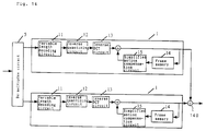
- Fig. 14 is a block diagram of a picture mixing apparatus for decoding and mixing the multiplexed compressed picture data.
- the multiplexed compressed picture data are separated depending on the identifier by a de-multiplex circuit 5, and fed into different picture decoding units 1.
- Each picture decoding unit 1 is the same as the picture decoding unit 1 in Fig. 11.
- the picture data obtained by decoding in the picture decoding units are added by an adder 140 to generate a mixed picture data.
- a mixed picture is obtained.
- plural picture decoding units 1 are necessary, but, for example, in the case of simultaneous broadcasting of multiple programs, when it is desired to mix same character information in each, the mixing devices are needed as many as the number of programs at the transmission side in embodiments 4 and 5, but only one is enough at the transmission side in this embodiment. Or, by selecting the identifier at the reception side, it is also possible to select the picture to be mixed.
- the sixth embodiment is an example of compressed picture data being compressed by prediction and coding, but this is not limitative, and it can be also applied to compressed picture data using only intraframe coding.
- the pictures decoded by the respective picture decoding units are added, but depending on the method of mixing pictures, it is possible to replace a part of one picture with a part of other picture.
- two picture decoding units are not needed, and by setting picture decoding in the same picture decoding unit at different times, a mixed picture may be obtained by a single picture decoding unit.
Landscapes
- Engineering & Computer Science (AREA)
- Multimedia (AREA)
- Signal Processing (AREA)
- Business, Economics & Management (AREA)
- Marketing (AREA)
- Compression Or Coding Systems Of Tv Signals (AREA)
Applications Claiming Priority (6)
| Application Number | Priority Date | Filing Date | Title |
|---|---|---|---|
| JP30178293A JP3188081B2 (ja) | 1993-12-01 | 1993-12-01 | 画像符号化方法および画像符号化装置 |
| JP301782/93 | 1993-12-01 | ||
| JP30178293 | 1993-12-01 | ||
| JP3974394 | 1994-03-10 | ||
| JP3974394A JP3186406B2 (ja) | 1994-03-10 | 1994-03-10 | 画像合成符号化方法及び画像合成装置 |
| JP39743/94 | 1994-03-10 |
Publications (3)
| Publication Number | Publication Date |
|---|---|
| EP0656729A2 true EP0656729A2 (fr) | 1995-06-07 |
| EP0656729A3 EP0656729A3 (fr) | 1996-08-07 |
| EP0656729B1 EP0656729B1 (fr) | 2000-02-09 |
Family
ID=26379116
Family Applications (1)
| Application Number | Title | Priority Date | Filing Date |
|---|---|---|---|
| EP94308669A Expired - Lifetime EP0656729B1 (fr) | 1993-12-01 | 1994-11-23 | Méthode et appareil pour éditer ou mixer des images comprimées |
Country Status (4)
| Country | Link |
|---|---|
| US (2) | US5912709A (fr) |
| EP (1) | EP0656729B1 (fr) |
| KR (1) | KR0161551B1 (fr) |
| DE (1) | DE69422960T2 (fr) |
Cited By (30)
| Publication number | Priority date | Publication date | Assignee | Title |
|---|---|---|---|---|
| EP0759617A3 (fr) * | 1995-08-18 | 1997-07-23 | Sony Corp | Système d'édition pour des signaux vidéo codé prédictivement |
| WO1997039587A1 (fr) * | 1996-04-12 | 1997-10-23 | Snell & Wilcox Limited | Procede et appareil pour boucler des trains binaires video comprimes |
| WO1998003017A1 (fr) * | 1996-07-15 | 1998-01-22 | Snell & Wilcox Limited | Compression de signaux video |
| EP0717410A3 (fr) * | 1994-12-12 | 1998-03-18 | Sony Corporation | Appareil et procédé de codage et/ou de décodage de données |
| GB2318246A (en) * | 1996-10-09 | 1998-04-15 | Sony Uk Ltd | Processing MPEG encoded video signals |
| EP0839374A4 (fr) * | 1995-05-08 | 1998-05-06 | ||
| WO1999004571A1 (fr) * | 1997-07-18 | 1999-01-28 | British Broadcasting Corporation | Commutation des trains binaires video compresses |
| EP0888007A4 (fr) * | 1996-03-13 | 1999-08-25 | Daikin Ind Ltd | Procede et dispositif d'edition partielle de donnees numeriques comprimees |
| FR2782437A1 (fr) * | 1998-08-14 | 2000-02-18 | Thomson Multimedia Sa | Procede de commutation de flux mpeg |
| EP0726679A4 (fr) * | 1994-08-26 | 2000-05-24 | Sony Corp | Procede et dispositif d'emission de donnees d'images comprimees |
| US6125140A (en) * | 1996-10-09 | 2000-09-26 | Sony Corporation | Processing encoded signals |
| GB2349770A (en) * | 1999-04-16 | 2000-11-08 | Sony Uk Ltd | Encoding a combined signal re-using parameters used to code one of the original signals |
| GB2349771A (en) * | 1999-04-16 | 2000-11-08 | Sony Uk Ltd | Re-using motion vetors to encode a combined picture signal |
| EP0734159A4 (fr) * | 1994-08-12 | 2001-02-07 | Sony Corp | Dispositif d'edition de signaux video |
| EP1081957A1 (fr) * | 1999-09-03 | 2001-03-07 | Sony United Kingdom Limited | Traitement d'un signal vidéo |
| EP0938236A3 (fr) * | 1998-02-19 | 2001-03-21 | Alcatel | Appareil et méthode pour la génération de points d'entrée dans un flux de données d'image |
| EP0984633A3 (fr) * | 1998-07-28 | 2001-04-11 | Sarnoff Corporation | Insertion d'un logo dans un signal vidéo |
| GB2355125A (en) * | 1999-09-03 | 2001-04-11 | Sony Uk Ltd | Re-using preserved parameters to encode a combined image signal |
| GB2356997A (en) * | 1999-12-02 | 2001-06-06 | Sony Uk Ltd | Video signal processing |
| EP1107603A1 (fr) * | 1999-12-02 | 2001-06-13 | Sony United Kingdom Limited | Traitement de signal vidéo |
| EP1005229A3 (fr) * | 1998-11-23 | 2001-06-20 | Hewlett-Packard Company, A Delaware Corporation | Dispositif et procédé pour la modification d'un signal vidéo comprimé |
| EP1126710A1 (fr) * | 2000-02-15 | 2001-08-22 | Telefonaktiebolaget L M Ericsson (Publ) | Une méthode et un système pour le mixage video de flux de données |
| WO1999056471A3 (fr) * | 1998-04-29 | 2001-08-23 | Hewlett Packard Co | Systeme de mise en forme de sequences d'images comprimees |
| EP1130595A1 (fr) * | 1998-11-25 | 2001-09-05 | Matsushita Electric Industrial Co., Ltd. | Appareil et procédé de montage de trains de données |
| GB2365647A (en) * | 2000-08-04 | 2002-02-20 | Snell & Wilcox Ltd | Deriving parameters for post-processing from an encoded signal |
| DE19825042C2 (de) * | 1997-09-12 | 2002-07-04 | Lg Electronics Inc | Verfahren zur Bewegungsvektorcodierung bei MPEG-4 |
| EP1309203A3 (fr) * | 2001-10-31 | 2004-09-15 | Eastman Kodak Company | Procédé et dispositif pour produire de transitions d'image |
| EP0987897A3 (fr) * | 1998-08-25 | 2005-07-13 | Matsushita Electric Industrial Co., Ltd. | Système de synthèse d'images animées |
| EP1868206A1 (fr) * | 2006-06-13 | 2007-12-19 | Sony Corporation | Appareil et procédé de traitement d'informations |
| US11006148B2 (en) | 2018-12-21 | 2021-05-11 | Axis Ab | Method and system for adding image content that contains one or more graphical objects to an image frame using an encoder |
Families Citing this family (55)
| Publication number | Priority date | Publication date | Assignee | Title |
|---|---|---|---|---|
| US5715009A (en) | 1994-03-29 | 1998-02-03 | Sony Corporation | Picture signal transmitting method and apparatus |
| JPH09322174A (ja) * | 1996-05-30 | 1997-12-12 | Hitachi Ltd | 動画データの再生方法 |
| JP3668556B2 (ja) * | 1996-06-13 | 2005-07-06 | ソニー株式会社 | ディジタル信号符号化方法 |
| KR100599017B1 (ko) * | 1996-12-12 | 2006-12-13 | 소니 가부시끼 가이샤 | 영상 데이터 압축 장치 및 그 방법 |
| US6483875B1 (en) * | 1997-06-19 | 2002-11-19 | Sony Corporation | Picture signal processing apparatus |
| JP3736808B2 (ja) * | 1997-07-25 | 2006-01-18 | ソニー株式会社 | 編集装置、編集方法、再符号化装置及び再符号化方法 |
| JP3529599B2 (ja) * | 1997-09-02 | 2004-05-24 | 株式会社東芝 | 符号化装置における編集可能点挿入方法および符号化装置 |
| JP3990011B2 (ja) * | 1997-10-31 | 2007-10-10 | 沖電気工業株式会社 | 復号画像変換回路および復号画像変換装置 |
| CA2265089C (fr) * | 1998-03-10 | 2007-07-10 | Sony Corporation | Systeme de transcodage utilisant les informations d'encodage |
| US6611624B1 (en) * | 1998-03-13 | 2003-08-26 | Cisco Systems, Inc. | System and method for frame accurate splicing of compressed bitstreams |
| JPH11275580A (ja) * | 1998-03-24 | 1999-10-08 | Sony Corp | 画像データ処理装置、画像データ復号装置及び画像データ符号化装置並びにそれらの方法 |
| US6912251B1 (en) * | 1998-09-25 | 2005-06-28 | Sarnoff Corporation | Frame-accurate seamless splicing of information streams |
| FR2784845B1 (fr) * | 1998-10-14 | 2001-02-23 | France Telecom | Procede de basculement de la ou des composantes video d'un premier programme audiovisuel sur la ou les composantes video d'un second programme audiovisuel numerique |
| JP3918332B2 (ja) * | 1998-12-04 | 2007-05-23 | ソニー株式会社 | 多重化装置、多重化方法及び記録媒体 |
| KR100571307B1 (ko) | 1999-02-09 | 2006-04-17 | 소니 가부시끼 가이샤 | 코딩 시스템 및 방법, 부호화 장치 및 방법, 복호화 장치및 방법, 기록 장치 및 방법, 및 재생 장치 및 방법 |
| US6973126B1 (en) * | 1999-03-05 | 2005-12-06 | Kdd Corporation | Video coding apparatus according to a feature of a video picture |
| JP2000333163A (ja) * | 1999-05-24 | 2000-11-30 | Sony Corp | 復号装置及び方法、符号化装置及び方法、画像処理システム、画像処理方法 |
| JP3694888B2 (ja) * | 1999-12-03 | 2005-09-14 | ソニー株式会社 | 復号装置および方法、符号化装置および方法、情報処理装置および方法、並びに記録媒体 |
| US6973130B1 (en) | 2000-04-25 | 2005-12-06 | Wee Susie J | Compressed video signal including information for independently coded regions |
| US6970510B1 (en) * | 2000-04-25 | 2005-11-29 | Wee Susie J | Method for downstream editing of compressed video |
| CA2349914C (fr) * | 2000-06-09 | 2013-07-30 | Invidi Technologies Corp. | Methode de livraison de messages publicitaires |
| US6901172B1 (en) * | 2000-09-27 | 2005-05-31 | Nec Corporation | Method and apparatus for drawing likeness |
| JP4524908B2 (ja) * | 2000-11-08 | 2010-08-18 | 日本電気株式会社 | 動画像編集方法、動画像編集装置及び動画像編集プログラムを記憶した記憶媒体 |
| US7197070B1 (en) * | 2001-06-04 | 2007-03-27 | Cisco Technology, Inc. | Efficient systems and methods for transmitting compressed video data having different resolutions |
| US7730509B2 (en) | 2001-06-08 | 2010-06-01 | Invidi Technologies Corporation | Asset delivery reporting in a broadcast network |
| WO2003001695A1 (fr) * | 2001-06-26 | 2003-01-03 | Cineform, Inc. | Procede et appareil pour l'edition en temps reel d'une pluralite de flots de contenu |
| US7096488B1 (en) | 2001-10-19 | 2006-08-22 | Cisco Technology, Inc. | Methods and apparatus for facilitating network splicing |
| US6990147B2 (en) * | 2001-10-23 | 2006-01-24 | Thomson Licensing | Generating a non-progressive dummy bidirectional predictive picture |
| US20030159152A1 (en) * | 2001-10-23 | 2003-08-21 | Shu Lin | Fast motion trick mode using dummy bidirectional predictive pictures |
| FR2848766B1 (fr) * | 2002-12-13 | 2005-03-11 | Thales Sa | Procede de commutation de signaux numeriques avant emission, commutateur et signal resultant |
| US9171577B1 (en) | 2003-04-25 | 2015-10-27 | Gopro, Inc. | Encoding and decoding selectively retrievable representations of video content |
| US7609762B2 (en) * | 2003-09-07 | 2009-10-27 | Microsoft Corporation | Signaling for entry point frames with predicted first field |
| US8213779B2 (en) | 2003-09-07 | 2012-07-03 | Microsoft Corporation | Trick mode elementary stream and receiver system |
| US7924921B2 (en) | 2003-09-07 | 2011-04-12 | Microsoft Corporation | Signaling coding and display options in entry point headers |
| US7852919B2 (en) * | 2003-09-07 | 2010-12-14 | Microsoft Corporation | Field start code for entry point frames with predicted first field |
| US7839930B2 (en) * | 2003-11-13 | 2010-11-23 | Microsoft Corporation | Signaling valid entry points in a video stream |
| EP1517562A3 (fr) * | 2003-09-19 | 2006-03-29 | Sony Corporation | Codage vidéo avec insertion d'information auxiliaire pour un traitement suivant, comme l'épissage, l'édition et l'attribution d'empreintes |
| JP4470431B2 (ja) * | 2003-10-01 | 2010-06-02 | ソニー株式会社 | データ処理装置およびその方法 |
| US20090094640A1 (en) * | 2007-09-26 | 2009-04-09 | Anderson Bruce J | Targeted advertising in unicast, multicast and hybrid distribution system contexts |
| PT1842369T (pt) | 2005-01-12 | 2020-06-18 | Invidi Tech Corp | Modelo de impressão direcionado para entrega de ativos de rede de difusão |
| US8014597B1 (en) | 2006-03-22 | 2011-09-06 | Woodman Labs | Method for efficient compression and decoding of single sensor color image data |
| WO2007111006A1 (fr) | 2006-03-27 | 2007-10-04 | Nec Corporation | Systeme, procede et programme de stockage d'image mobile |
| US20130254787A1 (en) | 2006-05-02 | 2013-09-26 | Invidi Technologies Corporation | Method and apparatus to perform real-time audience estimation and commercial selection suitable for targeted advertising |
| US7698236B2 (en) * | 2006-05-02 | 2010-04-13 | Invidi Technologies Corporation | Fuzzy logic based viewer identification for targeted asset delivery system |
| CA2654869C (fr) * | 2006-06-12 | 2016-08-30 | Invidi Technologies Corporation | Systeme et procede pour inserer des contenus multimedias d'apres une recherche par mot-cle |
| AU2007257684B2 (en) * | 2006-06-12 | 2012-03-15 | Invidi Technologies Corporation | System and method for auctioning avails |
| US7849477B2 (en) * | 2007-01-30 | 2010-12-07 | Invidi Technologies Corporation | Asset targeting system for limited resource environments |
| US8335266B2 (en) * | 2007-06-29 | 2012-12-18 | Cisco Technology, Inc. | Expedited splicing of video streams |
| JP5369425B2 (ja) * | 2007-10-31 | 2013-12-18 | 富士通株式会社 | 画像復元装置、画像復元プログラム、画像復元方法 |
| US20090161978A1 (en) * | 2007-12-20 | 2009-06-25 | Marinko Karanovic | Halo Artifact Removal Method |
| WO2009140691A2 (fr) | 2008-05-16 | 2009-11-19 | Invidi Technologies Corporation | Demande d’informations liée à un contenu de réseau de diffusion |
| CA2733193C (fr) | 2008-08-05 | 2016-11-01 | Invidi Technologies Corporation | Insertion nationale de publicite ciblee |
| WO2010017379A2 (fr) | 2008-08-06 | 2010-02-11 | Invidi Technologies Corporation | Appariement de données d’un tiers pour publicité ciblée |
| CA2750700C (fr) * | 2009-01-30 | 2018-11-27 | Invidi Technologies Corporation | Systeme et procede de vente par adjudication de messages de diffusion de contenu |
| KR101641716B1 (ko) * | 2009-09-02 | 2016-07-21 | 에스케이텔레콤 주식회사 | 통합 영상 부호화 방법 및 장치 |
Family Cites Families (14)
| Publication number | Priority date | Publication date | Assignee | Title |
|---|---|---|---|---|
| DE3437182A1 (de) * | 1984-10-10 | 1986-04-10 | Telefunken Fernseh Und Rundfunk Gmbh, 3000 Hannover | Verfahren zur aufzeichnung und/oder wiedergabe digital kodierter signale |
| JP2969782B2 (ja) * | 1990-05-09 | 1999-11-02 | ソニー株式会社 | 符号化データ編集方法及び符号化データ編集装置 |
| US5355450A (en) * | 1992-04-10 | 1994-10-11 | Avid Technology, Inc. | Media composer with adjustable source material compression |
| DE69334235D1 (de) * | 1992-01-29 | 2008-09-18 | Mitsubishi Electric Corp | Kodiergerät mit hoher Wirksamkeit und Vorrichtung zum Aufzeichnen/Wiedergeben von Videoinformation |
| JPH05236466A (ja) * | 1992-02-25 | 1993-09-10 | Nec Corp | 動き補償フレーム間予測画像符号化装置及び方法 |
| US5293229A (en) * | 1992-03-27 | 1994-03-08 | Matsushita Electric Corporation Of America | Apparatus and method for processing groups of fields in a video data compression system |
| US5367341A (en) * | 1992-10-20 | 1994-11-22 | Canon Information Systems, Inc. | Digital video editor having lost video frame protection |
| JP3036287B2 (ja) * | 1992-12-15 | 2000-04-24 | 富士ゼロックス株式会社 | 動画像シーン検出装置 |
| JP3282260B2 (ja) * | 1993-01-18 | 2002-05-13 | ソニー株式会社 | 画像再生装置及び方法 |
| US5477397A (en) * | 1993-02-23 | 1995-12-19 | Matsushita Electric Corporation Of America | Digital high definition television receiver with features that facilitate trick-play modes on a digital VCR |
| US5587806A (en) * | 1993-03-26 | 1996-12-24 | Matsushita Electric Industrial Co., Ltd. | Apparatus for separately recording input coded video signal and important data generated therefrom |
| US5555193A (en) * | 1993-05-25 | 1996-09-10 | Kabushiki Kaisha Toshiba | Video compression system with editing flag |
| EP0709009A1 (fr) * | 1993-06-16 | 1996-05-01 | GOULD, Kim V.W. | Systeme et procede de transmission de donnees video |
| US5485611A (en) * | 1994-12-30 | 1996-01-16 | Intel Corporation | Video database indexing and method of presenting video database index to a user |
-
1994
- 1994-11-23 EP EP94308669A patent/EP0656729B1/fr not_active Expired - Lifetime
- 1994-11-23 DE DE69422960T patent/DE69422960T2/de not_active Expired - Lifetime
- 1994-11-28 US US08/348,980 patent/US5912709A/en not_active Expired - Lifetime
- 1994-11-30 KR KR1019940031910A patent/KR0161551B1/ko not_active Expired - Lifetime
-
1998
- 1998-08-04 US US09/128,667 patent/US6088396A/en not_active Expired - Lifetime
Cited By (54)
| Publication number | Priority date | Publication date | Assignee | Title |
|---|---|---|---|---|
| EP0734159A4 (fr) * | 1994-08-12 | 2001-02-07 | Sony Corp | Dispositif d'edition de signaux video |
| EP1628306A3 (fr) * | 1994-08-12 | 2007-02-28 | Sony Corporation | Appareil d'édition de signaux de vidéo |
| EP0726679A4 (fr) * | 1994-08-26 | 2000-05-24 | Sony Corp | Procede et dispositif d'emission de donnees d'images comprimees |
| EP0717410A3 (fr) * | 1994-12-12 | 1998-03-18 | Sony Corporation | Appareil et procédé de codage et/ou de décodage de données |
| EP0839374A4 (fr) * | 1995-05-08 | 1998-05-06 | ||
| EP0759617A3 (fr) * | 1995-08-18 | 1997-07-23 | Sony Corp | Système d'édition pour des signaux vidéo codé prédictivement |
| US5835662A (en) * | 1995-08-18 | 1998-11-10 | Sony Corporation | Editing system for predictively encoded video signals |
| EP0888007A4 (fr) * | 1996-03-13 | 1999-08-25 | Daikin Ind Ltd | Procede et dispositif d'edition partielle de donnees numeriques comprimees |
| US6229851B1 (en) | 1996-04-12 | 2001-05-08 | Snell & Wilcox Limited | Method and apparatus for looping of compressed video bitstreams |
| AU715613B2 (en) * | 1996-04-12 | 2000-02-03 | Snell & Wilcox Limited | Method and apparatus for looping of compressed video bitstreams |
| WO1997039587A1 (fr) * | 1996-04-12 | 1997-10-23 | Snell & Wilcox Limited | Procede et appareil pour boucler des trains binaires video comprimes |
| US6674802B2 (en) | 1996-07-15 | 2004-01-06 | Snell & Wilcox Limited | Video process where part of compressed version of video signal accompanies video signal itself |
| AU738985B2 (en) * | 1996-07-15 | 2001-10-04 | British Broadcasting Corporation, The | Video signal compression |
| WO1998003017A1 (fr) * | 1996-07-15 | 1998-01-22 | Snell & Wilcox Limited | Compression de signaux video |
| EP2271103A3 (fr) * | 1996-07-15 | 2013-01-16 | Amstr. Investments 4 K.G., LLC | Compression de signaux vidéo |
| GB2318246A (en) * | 1996-10-09 | 1998-04-15 | Sony Uk Ltd | Processing MPEG encoded video signals |
| GB2318246B (en) * | 1996-10-09 | 2000-11-15 | Sony Uk Ltd | Processing digitally encoded signals |
| US6160844A (en) * | 1996-10-09 | 2000-12-12 | Sony Corporation | Processing digitally encoded signals |
| US6125140A (en) * | 1996-10-09 | 2000-09-26 | Sony Corporation | Processing encoded signals |
| GB2318472B (en) * | 1996-10-09 | 2000-11-15 | Sony Uk Ltd | Processing encoded signals |
| US6831949B1 (en) | 1997-07-18 | 2004-12-14 | British Broadcasting Corporation | Switching compressed video bitstreams |
| WO1999004571A1 (fr) * | 1997-07-18 | 1999-01-28 | British Broadcasting Corporation | Commutation des trains binaires video compresses |
| DE19825042C2 (de) * | 1997-09-12 | 2002-07-04 | Lg Electronics Inc | Verfahren zur Bewegungsvektorcodierung bei MPEG-4 |
| US6240136B1 (en) | 1998-02-19 | 2001-05-29 | Alcatel | Method of providing an access point into a video data stream and apparatus for carrying out the method |
| EP0938236A3 (fr) * | 1998-02-19 | 2001-03-21 | Alcatel | Appareil et méthode pour la génération de points d'entrée dans un flux de données d'image |
| WO1999056471A3 (fr) * | 1998-04-29 | 2001-08-23 | Hewlett Packard Co | Systeme de mise en forme de sequences d'images comprimees |
| EP0984633A3 (fr) * | 1998-07-28 | 2001-04-11 | Sarnoff Corporation | Insertion d'un logo dans un signal vidéo |
| FR2782437A1 (fr) * | 1998-08-14 | 2000-02-18 | Thomson Multimedia Sa | Procede de commutation de flux mpeg |
| EP0982948A1 (fr) * | 1998-08-14 | 2000-03-01 | THOMSON multimedia | Méthode de commutation de flux de données MPEG |
| EP0987897A3 (fr) * | 1998-08-25 | 2005-07-13 | Matsushita Electric Industrial Co., Ltd. | Système de synthèse d'images animées |
| EP1005229A3 (fr) * | 1998-11-23 | 2001-06-20 | Hewlett-Packard Company, A Delaware Corporation | Dispositif et procédé pour la modification d'un signal vidéo comprimé |
| US6683911B1 (en) | 1998-11-25 | 2004-01-27 | Matsushita Electric Industrial Co., Ltd. | Stream editing apparatus and stream editing method |
| EP1130595A1 (fr) * | 1998-11-25 | 2001-09-05 | Matsushita Electric Industrial Co., Ltd. | Appareil et procédé de montage de trains de données |
| GB2349770B (en) * | 1999-04-16 | 2003-09-24 | Sony Uk Ltd | Video signal processing |
| US6724436B1 (en) | 1999-04-16 | 2004-04-20 | Sony United Kingdom Limited | Video signal processing |
| GB2349770A (en) * | 1999-04-16 | 2000-11-08 | Sony Uk Ltd | Encoding a combined signal re-using parameters used to code one of the original signals |
| GB2349771A (en) * | 1999-04-16 | 2000-11-08 | Sony Uk Ltd | Re-using motion vetors to encode a combined picture signal |
| GB2349771B (en) * | 1999-04-16 | 2003-07-16 | Sony Uk Ltd | Video signal processing |
| US6567128B1 (en) | 1999-09-03 | 2003-05-20 | Sony United Kingdom Limited | Video signal processing in which first video information and additional video information are combined to produce frames that are encoded with different picture qualities for edge and non-edge regions |
| EP1081957A1 (fr) * | 1999-09-03 | 2001-03-07 | Sony United Kingdom Limited | Traitement d'un signal vidéo |
| GB2355125A (en) * | 1999-09-03 | 2001-04-11 | Sony Uk Ltd | Re-using preserved parameters to encode a combined image signal |
| US6757333B2 (en) | 1999-12-02 | 2004-06-29 | Sony United Kingdom Limited | Video signal processing |
| US6570923B2 (en) | 1999-12-02 | 2003-05-27 | Sony United Kingdom Limited | Video signal processing |
| EP1107603A1 (fr) * | 1999-12-02 | 2001-06-13 | Sony United Kingdom Limited | Traitement de signal vidéo |
| GB2356997A (en) * | 1999-12-02 | 2001-06-06 | Sony Uk Ltd | Video signal processing |
| GB2374234A (en) * | 2000-02-15 | 2002-10-09 | Ericsson Telefon Ab L M | A method and an apparatus for video mixing of bit streams |
| GB2374234B (en) * | 2000-02-15 | 2004-02-11 | Ericsson Telefon Ab L M | A method and an apparatus for video mixing of bit streams |
| EP1126710A1 (fr) * | 2000-02-15 | 2001-08-22 | Telefonaktiebolaget L M Ericsson (Publ) | Une méthode et un système pour le mixage video de flux de données |
| WO2001062001A1 (fr) * | 2000-02-15 | 2001-08-23 | Telefonaktiebolaget Lm Ericsson (Publ) | Procede et appareil de melange d'images de trains de bits |
| GB2365647A (en) * | 2000-08-04 | 2002-02-20 | Snell & Wilcox Ltd | Deriving parameters for post-processing from an encoded signal |
| EP1309203A3 (fr) * | 2001-10-31 | 2004-09-15 | Eastman Kodak Company | Procédé et dispositif pour produire de transitions d'image |
| US7148908B2 (en) | 2001-10-31 | 2006-12-12 | Eastman Kodak Company | Method and apparatus for generating image transitions |
| EP1868206A1 (fr) * | 2006-06-13 | 2007-12-19 | Sony Corporation | Appareil et procédé de traitement d'informations |
| US11006148B2 (en) | 2018-12-21 | 2021-05-11 | Axis Ab | Method and system for adding image content that contains one or more graphical objects to an image frame using an encoder |
Also Published As
| Publication number | Publication date |
|---|---|
| DE69422960D1 (de) | 2000-03-16 |
| EP0656729A3 (fr) | 1996-08-07 |
| KR950023014A (ko) | 1995-07-28 |
| US5912709A (en) | 1999-06-15 |
| EP0656729B1 (fr) | 2000-02-09 |
| DE69422960T2 (de) | 2000-06-15 |
| US6088396A (en) | 2000-07-11 |
| KR0161551B1 (ko) | 1999-01-15 |
Similar Documents
| Publication | Publication Date | Title |
|---|---|---|
| EP0656729B1 (fr) | Méthode et appareil pour éditer ou mixer des images comprimées | |
| KR100766740B1 (ko) | 부호화 히스토리 정보를 이용하는 데이터 변환 장치 및 방법 | |
| US6081551A (en) | Image coding and decoding apparatus and methods thereof | |
| EP0818930B1 (fr) | Procédé de codage vidéo | |
| US7194032B1 (en) | Circuit and method for modifying a region of an encoded image | |
| US6563954B2 (en) | Method for computational graceful degradation in an audiovisual compression system | |
| US6104441A (en) | System for editing compressed image sequences | |
| US6357045B1 (en) | Apparatus and method for generating a time-multiplexed channel surfing signal at television head-end sites | |
| US5633682A (en) | Stereoscopic coding system | |
| EP0582122B1 (fr) | Appareil de brouillage et appareil de débrouillage | |
| US6031575A (en) | Method and apparatus for encoding an image signal, method and apparatus for decoding an image signal, and recording medium | |
| US5737023A (en) | Hierarchical motion estimation for interlaced video | |
| US20050002458A1 (en) | Spatial scalable compression | |
| US20010055336A1 (en) | Compressed-video reencoder system for modifying the compression ratio of digitally encoded video programs | |
| EP0920214B1 (fr) | Appareil et dispositif de codage/décodage d'images en mouvement | |
| JP2001211455A (ja) | 画像符号化方法及び画像符号化装置 | |
| US6498816B1 (en) | Circuit and method for formatting each of a series of encoded video images into respective regions | |
| KR100238622B1 (ko) | 새로운 적응형 양자화기를 이용한 동영상 압축 시스템 및 방법 | |
| EP1051851B1 (fr) | Compression de signal video | |
| US7733954B2 (en) | Method of coding a video image stream with a view for subsequent recoding using the same type of code | |
| US6556714B2 (en) | Signal processing apparatus and method | |
| JP3186406B2 (ja) | 画像合成符号化方法及び画像合成装置 | |
| JP3461280B2 (ja) | 動画像編集装置および動画像編集方法 | |
| JPH06284415A (ja) | 動き補償予測符号化および復号化装置 |
Legal Events
| Date | Code | Title | Description |
|---|---|---|---|
| PUAI | Public reference made under article 153(3) epc to a published international application that has entered the european phase |
Free format text: ORIGINAL CODE: 0009012 |
|
| AK | Designated contracting states |
Kind code of ref document: A2 Designated state(s): DE FR GB IT NL |
|
| PUAL | Search report despatched |
Free format text: ORIGINAL CODE: 0009013 |
|
| AK | Designated contracting states |
Kind code of ref document: A3 Designated state(s): DE FR GB IT NL |
|
| 17P | Request for examination filed |
Effective date: 19961121 |
|
| 17Q | First examination report despatched |
Effective date: 19980714 |
|
| GRAG | Despatch of communication of intention to grant |
Free format text: ORIGINAL CODE: EPIDOS AGRA |
|
| GRAG | Despatch of communication of intention to grant |
Free format text: ORIGINAL CODE: EPIDOS AGRA |
|
| GRAH | Despatch of communication of intention to grant a patent |
Free format text: ORIGINAL CODE: EPIDOS IGRA |
|
| GRAH | Despatch of communication of intention to grant a patent |
Free format text: ORIGINAL CODE: EPIDOS IGRA |
|
| GRAA | (expected) grant |
Free format text: ORIGINAL CODE: 0009210 |
|
| AK | Designated contracting states |
Kind code of ref document: B1 Designated state(s): DE FR GB IT NL |
|
| ITF | It: translation for a ep patent filed | ||
| REF | Corresponds to: |
Ref document number: 69422960 Country of ref document: DE Date of ref document: 20000316 |
|
| ET | Fr: translation filed | ||
| PLBE | No opposition filed within time limit |
Free format text: ORIGINAL CODE: 0009261 |
|
| STAA | Information on the status of an ep patent application or granted ep patent |
Free format text: STATUS: NO OPPOSITION FILED WITHIN TIME LIMIT |
|
| 26N | No opposition filed | ||
| REG | Reference to a national code |
Ref country code: GB Ref legal event code: IF02 |
|
| PGFP | Annual fee paid to national office [announced via postgrant information from national office to epo] |
Ref country code: FR Payment date: 20131108 Year of fee payment: 20 Ref country code: GB Payment date: 20131120 Year of fee payment: 20 Ref country code: DE Payment date: 20131120 Year of fee payment: 20 |
|
| PGFP | Annual fee paid to national office [announced via postgrant information from national office to epo] |
Ref country code: IT Payment date: 20131111 Year of fee payment: 20 Ref country code: NL Payment date: 20131010 Year of fee payment: 20 |
|
| REG | Reference to a national code |
Ref country code: DE Ref legal event code: R071 Ref document number: 69422960 Country of ref document: DE |
|
| REG | Reference to a national code |
Ref country code: NL Ref legal event code: V4 Effective date: 20141123 |
|
| REG | Reference to a national code |
Ref country code: GB Ref legal event code: PE20 Expiry date: 20141122 |
|
| PG25 | Lapsed in a contracting state [announced via postgrant information from national office to epo] |
Ref country code: GB Free format text: LAPSE BECAUSE OF EXPIRATION OF PROTECTION Effective date: 20141122 |