EP1107603A1 - Traitement de signal vidéo - Google Patents
Traitement de signal vidéo Download PDFInfo
- Publication number
- EP1107603A1 EP1107603A1 EP00309757A EP00309757A EP1107603A1 EP 1107603 A1 EP1107603 A1 EP 1107603A1 EP 00309757 A EP00309757 A EP 00309757A EP 00309757 A EP00309757 A EP 00309757A EP 1107603 A1 EP1107603 A1 EP 1107603A1
- Authority
- EP
- European Patent Office
- Prior art keywords
- video signal
- compression
- key signal
- block
- video signals
- Prior art date
- Legal status (The legal status is an assumption and is not a legal conclusion. Google has not performed a legal analysis and makes no representation as to the accuracy of the status listed.)
- Withdrawn
Links
Images





Classifications
-
- H—ELECTRICITY
- H04—ELECTRIC COMMUNICATION TECHNIQUE
- H04N—PICTORIAL COMMUNICATION, e.g. TELEVISION
- H04N19/00—Methods or arrangements for coding, decoding, compressing or decompressing digital video signals
- H04N19/40—Methods or arrangements for coding, decoding, compressing or decompressing digital video signals using video transcoding, i.e. partial or full decoding of a coded input stream followed by re-encoding of the decoded output stream
-
- H—ELECTRICITY
- H04—ELECTRIC COMMUNICATION TECHNIQUE
- H04N—PICTORIAL COMMUNICATION, e.g. TELEVISION
- H04N19/00—Methods or arrangements for coding, decoding, compressing or decompressing digital video signals
- H04N19/10—Methods or arrangements for coding, decoding, compressing or decompressing digital video signals using adaptive coding
- H04N19/102—Methods or arrangements for coding, decoding, compressing or decompressing digital video signals using adaptive coding characterised by the element, parameter or selection affected or controlled by the adaptive coding
- H04N19/115—Selection of the code volume for a coding unit prior to coding
-
- H—ELECTRICITY
- H04—ELECTRIC COMMUNICATION TECHNIQUE
- H04N—PICTORIAL COMMUNICATION, e.g. TELEVISION
- H04N19/00—Methods or arrangements for coding, decoding, compressing or decompressing digital video signals
- H04N19/10—Methods or arrangements for coding, decoding, compressing or decompressing digital video signals using adaptive coding
- H04N19/102—Methods or arrangements for coding, decoding, compressing or decompressing digital video signals using adaptive coding characterised by the element, parameter or selection affected or controlled by the adaptive coding
- H04N19/124—Quantisation
-
- H—ELECTRICITY
- H04—ELECTRIC COMMUNICATION TECHNIQUE
- H04N—PICTORIAL COMMUNICATION, e.g. TELEVISION
- H04N19/00—Methods or arrangements for coding, decoding, compressing or decompressing digital video signals
- H04N19/10—Methods or arrangements for coding, decoding, compressing or decompressing digital video signals using adaptive coding
- H04N19/134—Methods or arrangements for coding, decoding, compressing or decompressing digital video signals using adaptive coding characterised by the element, parameter or criterion affecting or controlling the adaptive coding
- H04N19/146—Data rate or code amount at the encoder output
- H04N19/149—Data rate or code amount at the encoder output by estimating the code amount by means of a model, e.g. mathematical model or statistical model
-
- H—ELECTRICITY
- H04—ELECTRIC COMMUNICATION TECHNIQUE
- H04N—PICTORIAL COMMUNICATION, e.g. TELEVISION
- H04N19/00—Methods or arrangements for coding, decoding, compressing or decompressing digital video signals
- H04N19/10—Methods or arrangements for coding, decoding, compressing or decompressing digital video signals using adaptive coding
- H04N19/134—Methods or arrangements for coding, decoding, compressing or decompressing digital video signals using adaptive coding characterised by the element, parameter or criterion affecting or controlling the adaptive coding
- H04N19/146—Data rate or code amount at the encoder output
- H04N19/152—Data rate or code amount at the encoder output by measuring the fullness of the transmission buffer
-
- H—ELECTRICITY
- H04—ELECTRIC COMMUNICATION TECHNIQUE
- H04N—PICTORIAL COMMUNICATION, e.g. TELEVISION
- H04N19/00—Methods or arrangements for coding, decoding, compressing or decompressing digital video signals
- H04N19/10—Methods or arrangements for coding, decoding, compressing or decompressing digital video signals using adaptive coding
- H04N19/169—Methods or arrangements for coding, decoding, compressing or decompressing digital video signals using adaptive coding characterised by the coding unit, i.e. the structural portion or semantic portion of the video signal being the object or the subject of the adaptive coding
- H04N19/17—Methods or arrangements for coding, decoding, compressing or decompressing digital video signals using adaptive coding characterised by the coding unit, i.e. the structural portion or semantic portion of the video signal being the object or the subject of the adaptive coding the unit being an image region, e.g. an object
-
- H—ELECTRICITY
- H04—ELECTRIC COMMUNICATION TECHNIQUE
- H04N—PICTORIAL COMMUNICATION, e.g. TELEVISION
- H04N19/00—Methods or arrangements for coding, decoding, compressing or decompressing digital video signals
- H04N19/10—Methods or arrangements for coding, decoding, compressing or decompressing digital video signals using adaptive coding
- H04N19/169—Methods or arrangements for coding, decoding, compressing or decompressing digital video signals using adaptive coding characterised by the coding unit, i.e. the structural portion or semantic portion of the video signal being the object or the subject of the adaptive coding
- H04N19/17—Methods or arrangements for coding, decoding, compressing or decompressing digital video signals using adaptive coding characterised by the coding unit, i.e. the structural portion or semantic portion of the video signal being the object or the subject of the adaptive coding the unit being an image region, e.g. an object
- H04N19/176—Methods or arrangements for coding, decoding, compressing or decompressing digital video signals using adaptive coding characterised by the coding unit, i.e. the structural portion or semantic portion of the video signal being the object or the subject of the adaptive coding the unit being an image region, e.g. an object the region being a block, e.g. a macroblock
-
- H—ELECTRICITY
- H04—ELECTRIC COMMUNICATION TECHNIQUE
- H04N—PICTORIAL COMMUNICATION, e.g. TELEVISION
- H04N19/00—Methods or arrangements for coding, decoding, compressing or decompressing digital video signals
- H04N19/10—Methods or arrangements for coding, decoding, compressing or decompressing digital video signals using adaptive coding
- H04N19/169—Methods or arrangements for coding, decoding, compressing or decompressing digital video signals using adaptive coding characterised by the coding unit, i.e. the structural portion or semantic portion of the video signal being the object or the subject of the adaptive coding
- H04N19/182—Methods or arrangements for coding, decoding, compressing or decompressing digital video signals using adaptive coding characterised by the coding unit, i.e. the structural portion or semantic portion of the video signal being the object or the subject of the adaptive coding the unit being a pixel
-
- H—ELECTRICITY
- H04—ELECTRIC COMMUNICATION TECHNIQUE
- H04N—PICTORIAL COMMUNICATION, e.g. TELEVISION
- H04N19/00—Methods or arrangements for coding, decoding, compressing or decompressing digital video signals
- H04N19/10—Methods or arrangements for coding, decoding, compressing or decompressing digital video signals using adaptive coding
- H04N19/189—Methods or arrangements for coding, decoding, compressing or decompressing digital video signals using adaptive coding characterised by the adaptation method, adaptation tool or adaptation type used for the adaptive coding
- H04N19/196—Methods or arrangements for coding, decoding, compressing or decompressing digital video signals using adaptive coding characterised by the adaptation method, adaptation tool or adaptation type used for the adaptive coding being specially adapted for the computation of encoding parameters, e.g. by averaging previously computed encoding parameters
-
- H—ELECTRICITY
- H04—ELECTRIC COMMUNICATION TECHNIQUE
- H04N—PICTORIAL COMMUNICATION, e.g. TELEVISION
- H04N19/00—Methods or arrangements for coding, decoding, compressing or decompressing digital video signals
- H04N19/50—Methods or arrangements for coding, decoding, compressing or decompressing digital video signals using predictive coding
- H04N19/503—Methods or arrangements for coding, decoding, compressing or decompressing digital video signals using predictive coding involving temporal prediction
- H04N19/51—Motion estimation or motion compensation
-
- H—ELECTRICITY
- H04—ELECTRIC COMMUNICATION TECHNIQUE
- H04N—PICTORIAL COMMUNICATION, e.g. TELEVISION
- H04N19/00—Methods or arrangements for coding, decoding, compressing or decompressing digital video signals
- H04N19/60—Methods or arrangements for coding, decoding, compressing or decompressing digital video signals using transform coding
- H04N19/61—Methods or arrangements for coding, decoding, compressing or decompressing digital video signals using transform coding in combination with predictive coding
-
- H—ELECTRICITY
- H04—ELECTRIC COMMUNICATION TECHNIQUE
- H04N—PICTORIAL COMMUNICATION, e.g. TELEVISION
- H04N21/00—Selective content distribution, e.g. interactive television or video on demand [VOD]
- H04N21/40—Client devices specifically adapted for the reception of or interaction with content, e.g. set-top-box [STB]; Operations thereof
- H04N21/43—Processing of content or additional data, e.g. demultiplexing additional data from a digital video stream; Elementary client operations, e.g. monitoring of home network or synchronising decoder's clock; Client middleware
- H04N21/431—Generation of visual interfaces for content selection or interaction; Content or additional data rendering
Definitions
- This invention relates to video signal processing, for example, processing in which data (possibly compressed data) representing two or more video signals are mixed.
- wipe effect might be used to transition between two different scenes in a television programme, or a so-called logo or other computer-generated signal such as a subtitle or a set of credits might need to be superimposed over a video image without otherwise disrupting the underlying image.
- a key signal can be used to control the level of each of the constituent video signals (say, signals "A” and "B”) at each pixel position, with the two level-controlled signals then being added together.
- pixels are generally compressed as blocks known as macroblocks, so that it is not possible to derive the value of a particular pixel directly from the compressed video signal.
- Compressed video signals are also often subject to an overall limit on the quantity of data that can be used to transmit or store the signal. While there can be some variation from picture to picture, or even from group-of-pictures (GOP) to GOP, the time-averaged data rate is often constrained to the capacity of a transmission or storage channel. This allowable variation from picture to picture or GOP to GOP can mean that two signals to be combined can have the same nominal data rate but very different instantaneous data rates. So, when constructing a composite video signal from a group of video signals including one or more compressed signals, great care is needed to avoid a data overflow or underflow.
- GOP group-of-pictures
- a third feature of compressed video signals relevant to this discussion is that they often make use of motion vectors to indicate blocks of temporally preceding or following pictures which are similar to a block of a current picture and so can cut down the amount of data needed to encode the current picture.
- a motion vector for a current picture block can point to an area of a preceding or following image which has been replaced by or mixed with another input signal, so that the motion vector is no longer useful in the compression or decompression of that block.
- One way of handling these problems is to decompress the entire compressed input signals, carry out the mixing or similar process in the non-compressed domain, and then recompress the resulting composite pictures.
- the invention aims to address or at least alleviate at least one of these problems.
- This invention provides video signal processing apparatus in which at least two input video signals are combined in proportions determined by a pixel key signal to generate an output video signal for compression, at least one of the input video signals each having respective associated compression parameters from a data compression process applied to that video signal; the apparatus comprising:
- the invention provides an elegantly simple way of determining whether or not the compression parameters associated with an input video signal block may be re-used in the compression of an output video signal block.
- a basic decision is made to detect whether a set of compression parameters is not available for re-use, which is whether the corresponding block of the output image is not primarily derived from either or any of the individual input video signals.
- the test might be, in the exemplary case of two input video signals, whether the block contains between 25% and 75% of each input video signal.
- the compression parameters from the majority constituent input video signal can either be re-used directly or can be submitted for further testing to decide whether or not they should be used.
- FIGS 1 go 4 illustrate in schematic form some video processing operations which can be carried out to combine one video signal (A) with another video signal (B).
- Figures 1 and 2 are schematic "timeline" representations of a splice operation and a dissolve operation respectively.
- an abrupt change is made from signal A to signal B at a particular time t.
- a gradual change is made so that signal A is mixed into signal B over a particular time period.
- Figures 3 and 4 schematically illustrate television pictures themselves.
- Figure 3 illustrates a "logo" insertion, where a sub-portion of picture A is replaced by or mixed with picture B
- Figure 4 illustrates a wipe operation where the two pictures occupy complimentary portions of the screen and the boundary between the two is moveable.
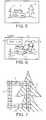
- Figures 5 to 7 show, again in schematic form, the superposition of a logo onto a video picture, that is to say a more detailed version of Figure 3.
- a video picture shows an original scene which may typically include moving objects 1,2 and static objects 3.
- additional video information including a textual logo 6 and further information such as a geographical map 5 is superposed over the original image.
- An example of circumstances in which this might be desired is to broadcast a warning of an impending occurrence such as a weather-related warning for a particular region, while not disturbing the underlying programme too much.
- Figure 7 is a schematic close-up view of part of Figure 6 showing the overlap between the static map 5 and parts of the original image 3.
- a block-based system such as MPEG 2, where each image is divided into so-called macroblocks, it can be seen that a number of macroblocks are affected by the overlap of the images.
- the macroblocks are illustrated as square blocks 10 in Figure 7.
- Figure 8 is a schematic diagram of a video signal processor.
- An encoder E1 receives an input video signal A and encodes it according to a desired output bit rate and GOP format. In situations where no mixing between the two video signals is required, the video signal encoded by the encoder E1 can be supplied directly for output via a switch S1 under the control of a controller 100.
- the encoder E1 is written in parentheses to illustrate the fact that if the input video signal is already in the required format, the encoder E1 may of course not be required.
- the output of the encoder E1 is supplied to a complimentary decoder D1 which decodes the video back to an uncompressed or "baseband" form.
- the baseband video signal is supplied to a mixer 110 and compression parameters used in the original compression in each block of the input video signal A are supplied to the controller 100.
- a source 120 of a video signal to be mixed, video B supplies video signal B to another encoder E3.
- E3 is shown in parentheses to illustrate the fact that it may not be required if the video signal B is already in a required format.
- the output of encoder E3 is a video signal at a corresponding bit rate and GOP format to that of the output of encoder E1, and is supplied to a further decoder D3 which derives compression parameters from the video signal and decodes video B back to baseband form for supply to the mixer 110.
- either of the encoder-decoder pairs E1/D1 or E3/D3 may be omitted and uncompressed or "baseband" video added in directly at one of the inputs of the mixer 110.
- the source 120 also supplies a key signal K to the mixer 110 (although the key signal could of course come from a different external source).
- the key signal defines the relative proportions of video A and video B to be used for each pixel of the required output image, and so the key signal K may vary between 0 (all video A to be used) and 1 (all video B to be used). This variation takes place on a pixel-by-pixel basis, with K values between 0 and 1 indicating a mix between the two signals at that position.
- the mixer 110 operates in a generally conventional manner, and on a pixel-by-pixel basis, to multiply pixels of video B by K at a multiplier 112, to multiply pixels of video A by (1-K) at a multiplier 114, and then to add the two products together at an adder 116 to generate pixels of an output mixed video signal.
- the mixed video signal is supplied to a further encoder E2, again operating to the same nominal bit rate and GOP format as E1 and E3, which serves to encode the mixed video signal for output via the switch S1.
- the controller 100 controls the operation of the encoder E2. In fundamental terms, the controller 100 controls whether the encoder E2 re-uses some or all of the compression parameters associated with the compression of blocks of the video signals A and B before they were mixed, or generates new compression parameters for encoding the blocks of the mixed video signal.
- the controller 100 receives details of the compression parameters of video signal A, details of the compression parameters of video signal B and a specification of a target output data rate (TBR).
- the controller 100 also accesses memory stores 130 in which various pieces of information including some derived from the key signal K may be retained.
- Figure 9 is a flowchart schematically illustrating the operation of the processor of Figure 8.
- the macroblocks of the mixed video signal are classified to establish whether they are considered to be wholly from video signal A, wholly from video signal B or a mixture of the two. This classification process will be described below with reference to Figure 11.
- the controller 100 establishes an estimate of the total number of bits required to encode the current frame of the mixed video signal. To do this, it does not actually apply a rate control algorithm to the mixed video signal, but instead calculates the estimate from historical data relating to the number of bits required to encode each macroblock of the two individual source video signals A and B. This process will be described in detail below.
- the controller compares the bit estimate for the current frame with the target data quantity TBR. If the bit estimate does not exceed TBR it is considered that there is not a data overflow and control passes to a step 245. If however the bit estimate exceeds TBR then it is considered that there is an overflow and control instead passes to a step 250.
- the next stage is to set a "threshold" value which will be used (as described in detail below) to determine which macroblocks should be recoded completely and which should re-use the parameters associated with one or both of the input video signals. This process will be described with reference to Figures 12 and 13 below.
- this threshold is set and used varies in dependence on whether an overflow was detected at the step 240.
- the threshold is set to a "simple" regime. This process for setting the threshold will be described with reference to Figure 10 below.
- the threshold is set by a more complex process.
- the threshold (used as described below, to determine which macroblocks should be re-encoded) is set in accordance with a look-up table (LUT) system to be described with reference to Figures 14 and 15a to 15c.
- a step 260 the quantisation parameters for video A and video B are compared with the threshold to determine a set of macroblocks to be re-encoded. This is shown in Figures 12 and 13. Control passes to the step 270.
- a test is carried out to determine whether the motion vectors associated with the macroblocks point to valid areas of reference images. For example, a macroblock may be wholly inside video A but its associated motion vector may point to a region replaced by video B in the reference frame. In these circumstances it would be inappropriate to use that motion vector. This process is described in detail below with reference to Figures 16a to 16d and 17.
- the full set of re-code or re-use parameter information is sent by the controller 100 to the encoder E2 which encodes the mixed video signal in accordance with this information.
- the controller 100 operates the switch S1 to select the output of encoder E2 for the entire frame.
- the encoder E2 includes a rate control algorithm.
- This may be, for example, a predictive rate control algorithms such as the so-called "test model 5" of the MPEG system, or maybe a pre-encode or rehearsal type rate control algorithm such as that described in GB-A-2 306 831.
- the parameters applied by the controller 100 to the rate control algorithm are identical to the original compression parameters received from the decoders D1 and D3 in the case of macroblocks where it has been determined that the parameters should be re-used, and, in the case of macroblocks where it has been determined that the parameters should not be re-used, comprise an indicator flag indicating to the rate control algorithm that new parameters should be derived.
- a special case here is the particular situation of an inserted logo, where in order to maintain the picture quality of the logo itself it may be desirable to specify a limit for the quantisation parameter for use on blocks containing logo material in order to set a maximum degree of harshness of the quantisation process. Again, that condition can be signalled from the controller 100 to the rate control algorithm in respect of macroblocks determined to contain primarily or all video B material. (This of course depends on a subjective decision as to whether the inserted video signal comprises a logo or other material, and this is naturally a decision made by the operator or user).
- the rate control algorithm of the encoder E2 generates compression parameters for those macroblocks to be re-encoded and then the encoder E2 encodes the whole frame on the basis of the received or derived parameters.
- FIG 11 schematically illustrates the classification of motion vectors (step 220 of Figure 9).
- K key value
- a comparator 310 compares them with two thresholds: a 75% threshold and a 25% threshold.
- the values of 25% and 75% are just examples and other values could be used instead.
- Any macroblocks for which the key_average value is detected to be 0% or 100% are determined to be from a single video source and so, unless an overflow situation is detected, are re-encoded using parameters associated with the majority video source.
- Macroblocks having a key_average value of under 25% or over 75% are determined to be primarily form a single video source. For example, if a macroblock's key_average signal indicates that the average contribution of video source A to that macroblock is 90% and of video source B 10%, then the macroblock is determined by this technique to be primarily from video source A. In the absence of an overflow situation, the macroblock is flagged to be tested by comparing the quantisation parameter of the majority video source against a threshold. If it passes this test, it is then encoded re-using the compression parameters of the corresponding macroblock of the majority video source (video source A in the example above).
- Any macroblocks having a key_average value between 25% and 75% are set to a "re-encode" status. These macroblocks are re-encoded with fresh encoding parameters being generated.
- step 230 The calculation (in step 230) of the variable total_bit_estimate for the frame will now be described. This calculation makes use of the key_average values derived for each macroblock in Figure 11 and also of the historical number of bits required to encode each macroblock of the two input video signals A & B, obtained from the decoders D1 and D3.
- total_bit_estimate MB(A) _ total_ bits + MB(B) _ total_bits + MB(A + B) _ total _ bits
- Bits ( N ) [ key_average * bits ( N_B ) ]+ [( 100% - key_average ) * bits ( N _ A )] where bits (N_A) is the number of bits in respect of that macroblock of video A and bits (N_B) is the number of bits in respect of that macroblock of video B.
- variable total_bit_estimate is compared (step 240 of Figure 9) with the target data quantity for the frame TBR by a simple comparator (not shown).
- FIG. 10 schematically illustrates this process, where a multiplexer 320 selects a threshold value of (in this example) 0%, 0% or 30% dependent on whether the current frame is an B, P or I frame respectively.
- a threshold value of (in this example) 0%, 0% or 30% dependent on whether the current frame is an B, P or I frame respectively.
- different thresholds can be set for the three different types of frame.
- the thresholds for P and B frames can differ from one another - for example, a set of thresholds could be used having I: 40%; P: 30% and B: 20% could be used.
- the process by which the thresholds are used will be described below, but put simply, a higher threshold implies that fewer macroblocks will be re-encoded.
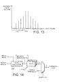
- Figure 14 schematically illustrates an arrangement for deriving a threshold value from a set of look-up tables (LUTs).
- a ratio calculator 330 receives four sets of information:
- variable MB_ratio determines which of a number of LUTs should be used. There may also be separate sets of LUTs applicable to I, P and B frames, in which case MB_ratio selects a LUT from the set of LUTs applicable to the current frame type.
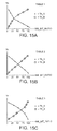
- Figures 15a to 15c Examples of some LUTs are shown in Figures 15a to 15c.
- Figure 15a schematically shows a LUT applicable to lower values of MB_ratio, Figure 15b to mid-values of MB_ratio and Figure 15c to upper values of MB_ratio.
- Figure 15c schematically shows a LUT applicable to lower values of MB_ratio
- Figure 15b to mid-values of MB_ratio
- Figure 15c to upper values of MB_ratio.
- the number of tables used in a particular system, and the ranges of MB_ratio which select each such table are routine design decisions well within the capability of the skilled man.
- each table defines two threshold amounts, Th_A and Th_B for different values of MB_bit_ratio between 0% and 100%. So, once the appropriate table has been selected, the value calculated for MB_bit_ratio for the current frame selects respective values of Th_A and Th_B.
- the crossover between the two curves for Th_A and Th_B is at an MB_bit_ratio value of about 25%; in table 2 it is about 50% and in table 3 it is about 75%.
- the threshold value - either the single threshold value developed from the "simple" scheme of step 245 or the pair of values Th_A and Th_B developed from the LUTs of step 250 - is applied to the macroblocks to determine which macroblocks should be re-encoded will now be described with reference to Figures 12 and 13.
- the comparison of quantisation parameters Q with the threshold(s) set as described above is used to determine whether or not some of the macroblocks are to be re-encoded or to have their original parameters re-used. Although shown as a single step in Figure 9, this process differs in dependence on whether an overflow has been detected.
- the Q values from all of the macroblocks under consideration are received by a Q threshold calculator 350 and stored in one of the stores 130.
- the Q threshold calculator then orders the Q values in ascending numerical order and derives the incidence of each possible Q value over the macroblocks of interest.
- a schematic histogram illustrating this process is shown in Figure 13.
- the threshold x% is then applied to this distribution, so that the highest Q value for which the cumulative incidence up to that Q value lies within the threshold proportion x% is established.
- a Q value 370 in Figure 12 fulfils this requirement for the distribution shown.
- Macroblocks, of those under consideration, having Q values up to and including that highest Q value 370 are then encoded re-using their original encoding parameters, or at least those of the majority component of the macroblock.
- Macroblocks, of those under consideration, for which the Q value exceeds the highest Q value 370 are re-encoded with fresh coefficients.
- the Q values are read out from the store 130 and compared at a comparator 360 with Q TH. The determination of whether to re-encode or to re-use is thus made.
- Any macroblocks having a key_average value of 0% or 100% have their original parameters re-used.
- Any macroblocks for which the "re-encode" flag is set i.e. those for which 25% ⁇ key_average ⁇ 75% are re-encoded with fresh parameters generated by the encoder E2.
- Any macroblocks not fulfilling either of the above conditions i.e. those for which the key_average value is not 0% or 100% but is less than 25% or more than 75%, are tested as described above.
- This test takes place in two stages: one stage covers those macroblocks having a key_average value less than 25%, and for this stage the distribution of Q values from all macroblocks of picture A is assessed by the calculator 350 to determine a distribution and a value of Q TH. The derived value of Q TH is then applied to the macroblocks having a nonzero key_average value less than 25%.
- a second stage does the same for macroblocks which are primarily of video B, that is to say, those macroblocks having a key_average value greater than 75%, and for this stage the distribution of Q values from all macroblocks of picture B is assessed by the calculator 350 to determine a distribution and a value of Q TH. The derived value of Q TH is then applied to the macroblocks having a non-unity key_average value greater than 75%.
- the above process leads to a proportion of the macroblocks under consideration being re-used and a proportion being re-encoded. If the threshold x is set to 0%, as in one of the examples above, then it follows that all of the macroblocks to which that test is applied are re-encoded.
- the complex threshold scheme involving LUTs is used. This generates separate thresholds for video A macroblocks and video B macroblocks, namely Th_A and Th_B.
- the test takes place in two stages: one stage covers those macroblocks having a key_average value of 0%, and for this stage the distribution of Q values from all macroblocks of picture A having a key_average value of 0% is assessed by the calculator 350 using the threshold Th_A to determine a distribution and a value of Q TH. The derived value of Q TH is then applied to the macroblocks having a key_average value of 0%.
- the process differs in that the distribution detected by the calculator 350 is not that of the whole of picture A, but that of only those macroblocks having a key_average value of 0%.
- the second stage covers those macroblocks having a key_average value of 100%, and for this stage the distribution of Q values from all macroblocks of picture B having a key_average value of 100% is assessed by the calculator 350 using the threshold Th_B to determine a distribution and a value of Q TH. The derived value of Q TH is then applied to the macroblocks having a key_average value of 100%.
- Figures 16a to 16d and 17 illustrate the processes carried out at the step 270 of Figure 9, that is to say, applying borders to boundaries between regions from the two video sources and then testing motion vectors to be re-used to determine whether they point to appropriate parts of the material from the same video source.
- Figure 16a schematically shows an image formed partly of video A and partly of video B. The boundary between the two regions is shown by a solid line.
- a border is created around all macroblocks which are not entirely derived from region A ( Figure 16a) and a border is created around all macroblocks which are not entirely derived from region B ( Figure 16b).
- GB9908812.2 and GB9920930.6 the general principle of GB9908812.2 and GB9920930.6 is that if a motion vector associated with a macroblock from region B points or refers to either region A, macroblocks which are not entirely from region B or the border created around those macroblocks not entirely from region B, it is not re-used but instead a new motion vector is generated in its place. Similarly, if a motion vector associated with a macroblock from region A points to either region B, macroblocks not entirely from region A or the border created around those macroblocks not entirely from region A, again it is not re-used but instead a new motion vector is generated in its place.
- the two borders are combined to give a single composite border as shown schematically in Figure 16d. This reduces the amount of storage needed (by about half) and also reduces the amount of processing needed in the vector testing process, as effectively the same test is applied to vectors from region A or region B. So, a motion vector for a macroblock of A is rejected if it points or refers to:
- a motion vector from a macroblock in either region A or region B points or refers to: either a position within the other region or partly derived from that region; or a position within the composite border then that macroblock is flagged to require new motion vectors, which are then generated by the encoder E2.
- Figure 17 shows the testing of the forward and backward motion vectors associated with a B frame.
- the controller 100 maintains three stores in connection with this testing process (which contrasts with five stores for the previously proposed system): a current store, a backward store and a forward store.
- a current store which contrasts with five stores for the previously proposed system
- a backward store which macroblocks which are classified as being from either source A or source B are flagged and a border is created around each region.
- Each macroblock form the current store then has its motion vector(s) tested against the forward and backward stores as described above.
- references to "frames" in the above description are by way of example only - in general the encoding is picture by picture, which could be frames, fields, a combination or other pictures.
Landscapes
- Engineering & Computer Science (AREA)
- Multimedia (AREA)
- Signal Processing (AREA)
- Physics & Mathematics (AREA)
- Algebra (AREA)
- General Physics & Mathematics (AREA)
- Mathematical Analysis (AREA)
- Mathematical Optimization (AREA)
- Pure & Applied Mathematics (AREA)
- Computing Systems (AREA)
- Theoretical Computer Science (AREA)
- Compression Or Coding Systems Of Tv Signals (AREA)
- Controls And Circuits For Display Device (AREA)
- Studio Circuits (AREA)
Applications Claiming Priority (2)
| Application Number | Priority Date | Filing Date | Title |
|---|---|---|---|
| GB9928525 | 1999-12-02 | ||
| GB9928525A GB2356998A (en) | 1999-12-02 | 1999-12-02 | Video signal processing |
Publications (1)
| Publication Number | Publication Date |
|---|---|
| EP1107603A1 true EP1107603A1 (fr) | 2001-06-13 |
Family
ID=10865599
Family Applications (1)
| Application Number | Title | Priority Date | Filing Date |
|---|---|---|---|
| EP00309757A Withdrawn EP1107603A1 (fr) | 1999-12-02 | 2000-11-03 | Traitement de signal vidéo |
Country Status (4)
| Country | Link |
|---|---|
| US (1) | US6757333B2 (fr) |
| EP (1) | EP1107603A1 (fr) |
| JP (1) | JP2001211453A (fr) |
| GB (1) | GB2356998A (fr) |
Families Citing this family (10)
| Publication number | Priority date | Publication date | Assignee | Title |
|---|---|---|---|---|
| EP1324615A1 (fr) * | 2001-12-28 | 2003-07-02 | Deutsche Thomson-Brandt Gmbh | Transcodage de flux MPEG pour l'addition du contenu de sous-images |
| US7190723B2 (en) * | 2002-03-27 | 2007-03-13 | Scientific-Atlanta, Inc. | Digital stream transcoder with a hybrid-rate controller |
| GB2407675B (en) * | 2002-09-30 | 2006-01-04 | Adobe Systems Inc | Reduction of search ambiguity with multiple media references |
| US20060085827A1 (en) * | 2004-10-18 | 2006-04-20 | Toshiro Ozawa | Entertainment content preprocessing |
| GB2438004B (en) * | 2006-05-08 | 2011-08-24 | Snell & Wilcox Ltd | Creation and compression of video data |
| JP5399277B2 (ja) * | 2010-01-20 | 2014-01-29 | 株式会社メガチップス | 画像圧縮装置、オーサリングシステムおよび画像圧縮方法 |
| EP2568704A4 (fr) * | 2010-05-06 | 2013-12-18 | Nippon Telegraph & Telephone | Procédé et appareil de commande de codage vidéo |
| KR101389919B1 (ko) * | 2010-05-07 | 2014-04-30 | 니폰덴신뎅와 가부시키가이샤 | 동화상 부호화 제어 방법, 동화상 부호화 장치 및 동화상 부호화 프로그램 |
| EP2571268B1 (fr) | 2010-05-12 | 2019-11-27 | Nippon Telegraph And Telephone Corporation | Procédé de commande de codage vidéo, dispositif de codage vidéo et programme de codage vidéo |
| WO2020112193A1 (fr) | 2018-11-26 | 2020-06-04 | Google Llc | Compression vidéo uniforme sécurisée et inter-dispositifs |
Citations (2)
| Publication number | Priority date | Publication date | Assignee | Title |
|---|---|---|---|---|
| EP0656729A2 (fr) * | 1993-12-01 | 1995-06-07 | Matsushita Electric Industrial Co., Ltd. | Méthode et appareil pour éditer ou mixer des images comprimées |
| WO1998036571A1 (fr) * | 1997-02-14 | 1998-08-20 | At & T Corp. | Procede et appareil de codage de regions d'images segmentees au moyen de deux seuils d'incrustation couleur |
Family Cites Families (8)
| Publication number | Priority date | Publication date | Assignee | Title |
|---|---|---|---|---|
| JP3042062B2 (ja) * | 1991-08-28 | 2000-05-15 | ソニー株式会社 | 画像処理装置 |
| GB9217098D0 (en) * | 1992-08-12 | 1992-09-23 | British Broadcasting Corp | Derivation of studio camera position and motion from the camera image |
| US5668609A (en) * | 1994-09-08 | 1997-09-16 | Tektronix, Inc. | Motion detector and key signal interpolator using same |
| JP4388598B2 (ja) * | 1995-02-22 | 2009-12-24 | コーニンクレッカ フィリップス エレクトロニクス エヌ ヴィ | 伝送チャネルを介して複数のビデオプログラムを同時に送信するシステム |
| GB2305050A (en) * | 1995-09-08 | 1997-03-26 | Orad Hi Tec Systems Ltd | Determining the position of a television camera for use in a virtual studio employing chroma keying |
| US6208693B1 (en) * | 1997-02-14 | 2001-03-27 | At&T Corp | Chroma-key for efficient and low complexity shape representation of coded arbitrary video objects |
| JP3560217B2 (ja) * | 1998-04-30 | 2004-09-02 | ソニー株式会社 | データ符号化装置、データ符号化方法及びデータ伝送方法 |
| US6647535B1 (en) * | 1999-03-18 | 2003-11-11 | Xerox Corporation | Methods and systems for real-time storyboarding with a web page and graphical user interface for automatic video parsing and browsing |
-
1999
- 1999-12-02 GB GB9928525A patent/GB2356998A/en not_active Withdrawn
-
2000
- 2000-11-03 EP EP00309757A patent/EP1107603A1/fr not_active Withdrawn
- 2000-11-30 JP JP2000365688A patent/JP2001211453A/ja not_active Withdrawn
- 2000-12-01 US US09/728,810 patent/US6757333B2/en not_active Expired - Fee Related
Patent Citations (2)
| Publication number | Priority date | Publication date | Assignee | Title |
|---|---|---|---|---|
| EP0656729A2 (fr) * | 1993-12-01 | 1995-06-07 | Matsushita Electric Industrial Co., Ltd. | Méthode et appareil pour éditer ou mixer des images comprimées |
| WO1998036571A1 (fr) * | 1997-02-14 | 1998-08-20 | At & T Corp. | Procede et appareil de codage de regions d'images segmentees au moyen de deux seuils d'incrustation couleur |
Non-Patent Citations (1)
| Title |
|---|
| SHIH-FU CHANG ET AL: "MANIPULATION AND COMPOSITING OF MC-DCT COMPRESSED VIDEO", IEEE JOURNAL ON SELECTED AREAS IN COMMUNICATIONS,US,IEEE INC. NEW YORK, vol. 13, no. 1, 1995, pages 1 - 11, XP000492740, ISSN: 0733-8716 * |
Also Published As
| Publication number | Publication date |
|---|---|
| GB9928525D0 (en) | 2000-02-02 |
| GB2356998A (en) | 2001-06-06 |
| US6757333B2 (en) | 2004-06-29 |
| US20010003534A1 (en) | 2001-06-14 |
| JP2001211453A (ja) | 2001-08-03 |
Similar Documents
| Publication | Publication Date | Title |
|---|---|---|
| US7023914B2 (en) | Video encoding apparatus and method | |
| US5654759A (en) | Methods and apparatus for reducing blockiness in decoded video | |
| US6278735B1 (en) | Real-time single pass variable bit rate control strategy and encoder | |
| US7805016B2 (en) | Decoding apparatus and decoding method | |
| US6122400A (en) | Compression encoder bit allocation utilizing colormetric-adaptive weighting as in flesh-tone weighting | |
| EP1081957B1 (fr) | Traitement d'un signal vidéo | |
| US6301301B1 (en) | Apparatus and method for coding and decoding a moving image | |
| US20050094870A1 (en) | Video encoding method and video encoding apparatus | |
| US20040001638A1 (en) | Rate allocation for mixed content video | |
| US8064517B1 (en) | Perceptually adaptive quantization parameter selection | |
| US7809198B2 (en) | Coding apparatus having rate control to prevent buffer breakdown | |
| WO2011080925A1 (fr) | Dispositif et procédé de codage d'image | |
| CN110225343B (zh) | 一种视频编码的码率控制方法及装置 | |
| US6757333B2 (en) | Video signal processing | |
| US7925108B2 (en) | Encoding device and dynamic image recording system having the encoding device | |
| US6643325B2 (en) | Video signal processing | |
| US7714751B2 (en) | Transcoder controlling generated codes of an output stream to a target bit rate | |
| US6570923B2 (en) | Video signal processing | |
| JP2003179921A (ja) | 符号化映像復号化装置 | |
| US6724436B1 (en) | Video signal processing | |
| GB2412807A (en) | Video processing to reduce program length | |
| JPH06133301A (ja) | 動画像圧縮符号化方法 | |
| GB2349771A (en) | Re-using motion vetors to encode a combined picture signal | |
| GB2355125A (en) | Re-using preserved parameters to encode a combined image signal | |
| JP4689001B2 (ja) | ビデオ信号処理装置、コンピュータプログラム及びビデオ信号処理方法 |
Legal Events
| Date | Code | Title | Description |
|---|---|---|---|
| PUAI | Public reference made under article 153(3) epc to a published international application that has entered the european phase |
Free format text: ORIGINAL CODE: 0009012 |
|
| AK | Designated contracting states |
Kind code of ref document: A1 Designated state(s): DE FR GB |
|
| AX | Request for extension of the european patent |
Free format text: AL;LT;LV;MK;RO;SI |
|
| 17P | Request for examination filed |
Effective date: 20011203 |
|
| AKX | Designation fees paid |
Free format text: DE FR |
|
| RBV | Designated contracting states (corrected) |
Designated state(s): DE FR GB |
|
| 17Q | First examination report despatched |
Effective date: 20071113 |
|
| STAA | Information on the status of an ep patent application or granted ep patent |
Free format text: STATUS: THE APPLICATION IS DEEMED TO BE WITHDRAWN |
|
| 18D | Application deemed to be withdrawn |
Effective date: 20080326 |